EP1238881A1 - Angetriebenes Schienenfahrzeug, insbesondere für die Personenbeförderung im Nah und Regionalverkehr - Google Patents
Angetriebenes Schienenfahrzeug, insbesondere für die Personenbeförderung im Nah und Regionalverkehr Download PDFInfo
- Publication number
- EP1238881A1 EP1238881A1 EP02004172A EP02004172A EP1238881A1 EP 1238881 A1 EP1238881 A1 EP 1238881A1 EP 02004172 A EP02004172 A EP 02004172A EP 02004172 A EP02004172 A EP 02004172A EP 1238881 A1 EP1238881 A1 EP 1238881A1
- Authority
- EP
- European Patent Office
- Prior art keywords
- mounting element
- rail vehicle
- vehicle according
- internal combustion
- combustion engine
- Prior art date
- Legal status (The legal status is an assumption and is not a legal conclusion. Google has not performed a legal analysis and makes no representation as to the accuracy of the status listed.)
- Granted
Links
- 238000002485 combustion reaction Methods 0.000 claims abstract description 16
- 238000009434 installation Methods 0.000 claims description 7
- 239000002828 fuel tank Substances 0.000 claims description 4
- 239000011521 glass Substances 0.000 claims description 2
- 230000010354 integration Effects 0.000 claims description 2
- 238000012423 maintenance Methods 0.000 claims description 2
- 238000013016 damping Methods 0.000 claims 2
- 230000003137 locomotive effect Effects 0.000 abstract description 4
- 230000003584 silencer Effects 0.000 description 6
- 238000005516 engineering process Methods 0.000 description 2
- 239000000969 carrier Substances 0.000 description 1
- 238000010276 construction Methods 0.000 description 1
- 239000000446 fuel Substances 0.000 description 1
- 239000003502 gasoline Substances 0.000 description 1
- 230000000717 retained effect Effects 0.000 description 1
- 238000009420 retrofitting Methods 0.000 description 1
- 239000000779 smoke Substances 0.000 description 1
Images


Classifications
-
- B—PERFORMING OPERATIONS; TRANSPORTING
- B61—RAILWAYS
- B61C—LOCOMOTIVES; MOTOR RAILCARS
- B61C7/00—Other locomotives or motor railcars characterised by the type of motive power plant used; Locomotives or motor railcars with two or more different kinds or types of motive power
- B61C7/04—Locomotives or motor railcars with two or more different kinds or types of engines, e.g. steam and IC engines
-
- B—PERFORMING OPERATIONS; TRANSPORTING
- B60—VEHICLES IN GENERAL
- B60L—PROPULSION OF ELECTRICALLY-PROPELLED VEHICLES; SUPPLYING ELECTRIC POWER FOR AUXILIARY EQUIPMENT OF ELECTRICALLY-PROPELLED VEHICLES; ELECTRODYNAMIC BRAKE SYSTEMS FOR VEHICLES IN GENERAL; MAGNETIC SUSPENSION OR LEVITATION FOR VEHICLES; MONITORING OPERATING VARIABLES OF ELECTRICALLY-PROPELLED VEHICLES; ELECTRIC SAFETY DEVICES FOR ELECTRICALLY-PROPELLED VEHICLES
- B60L2200/00—Type of vehicles
- B60L2200/26—Rail vehicles
-
- Y—GENERAL TAGGING OF NEW TECHNOLOGICAL DEVELOPMENTS; GENERAL TAGGING OF CROSS-SECTIONAL TECHNOLOGIES SPANNING OVER SEVERAL SECTIONS OF THE IPC; TECHNICAL SUBJECTS COVERED BY FORMER USPC CROSS-REFERENCE ART COLLECTIONS [XRACs] AND DIGESTS
- Y02—TECHNOLOGIES OR APPLICATIONS FOR MITIGATION OR ADAPTATION AGAINST CLIMATE CHANGE
- Y02T—CLIMATE CHANGE MITIGATION TECHNOLOGIES RELATED TO TRANSPORTATION
- Y02T30/00—Transportation of goods or passengers via railways, e.g. energy recovery or reducing air resistance
Definitions
- the invention relates to a driven rail vehicle, in particular for local and regional passenger transport, with at least one electric traction motor, via a stationary network or through a generator coupled to an internal combustion engine is, the internal combustion engine and the generator by a Mounting element that can be connected on the vehicle to form a drive assembly are united.
- DE 197 18 425 A1 describes a rail-bound one designed for the transport of goods Transport unit known, the two similar to a locomotive Power heads and loading wagons arranged between them to accommodate Has swap bodies.
- the drive system is designed in hybrid construction, d. i.e., next to one Electric motor is an internal combustion engine in the form of a diesel engine or gasoline engine that operates a generator. By a switch, it is possible to either use the electric motor depending on the network via a pantograph or via the generator Food.
- the transport unit according to DE 197 18 425 A1 can therefore be electrified Routes and also on non-electrified routes.
- EP 0 718 169 is also a rail wagon intended for the transportation of goods with its own drive block.
- the one in a container-like Frame structure integrated and held under the car frame Drive block includes, for example, an internal combustion engine as the drive unit, a fuel tank and also for a fully automatic one Operation of the rail car required control and safety devices.
- this rail car is not a Hybrid vehicle.
- EP 0 633 173 B1 also includes a multi-part railcar for the State-of-the-art passenger transport, electric traction motors having. These traction motors can optionally be powered by a pantograph via a stationary line network or by a generator with a diesel engine operate. The generator and the diesel engine are on a support frame mounted elastically, which is arranged on the roof of a car part.
- the invention has for its object in a rail vehicle generic type the drive module as an accessory module if required to install or remove quickly and particularly easily accessible.
- the container trained mounting element at least the internal combustion engine and takes the generator and through an existing opening of the vehicle outer wall can be used in the vehicle.
- This solution advantageously offers the possibility of, for example, light rail vehicles, according to the wishes of the transport companies from similar modules be composed differently and mainly on electrified Routes are to be operated by means of an accessory module "drive assembly" also for additional operation on non-electrified lines to be able to use. It is very easy to do the drive assembly to be retrofitted because there is an existing opening on the outside of the vehicle , preferably a door opening, can be used.
- the Car body is always identical, so that the basic principle of the modular design is retained. Because of the quick and easily accessible possible installation and removal of the drive assembly can also Retrofitting z. B. for adapting to the current state of engine technology (like innovative exhaust technology) can be carried out easily.
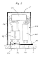
- the rail vehicle shown in FIGS. 1 and 2 is a three-part tram or light rail cars, each with two drive modules 13 a head module 14 and a middle module 15 is formed.
- the modules 13 and 15 contain passenger seats 16.
- the drive modules 13 point in the area their trolleys arranged electric traction motors 1, which have a Current collectors 17 are fed from a stationary line network 2 can.
- the outer wall 9 of the vehicle is provided with openings 6, at which are in particular openings 6 'for entrance doors and openings 6 "for window panes.
- a drive module as an accessory module provided that a container-like and at least an internal combustion engine 3 and a generator 4 Mounting element 5 includes.
- an internal combustion engine 3 a petrol engine, a diesel engine or a fuel cell.
- two of the are due to a higher drive power said mounting elements 5 provided (see Fig. 2), each by a door opening 6 'are inserted into the vehicle and on the vehicle floor 7 stand.
- the mounting element is for simple and quick installation 5 with points of attack for z. B. a pallet truck as an assembly tool Mistake.
- for inserting at least one Mounting element 5 in the vehicle are one of the window openings 6 "or, for example, below a window opening 6" Installation opening that are exposed by removing a side panel can. All cases are easily accessible installation or removal of the mounting element 5 from the vehicle side.
- the one problem with regard to the roof-side arrangement of the drive assembly compliance with the vehicle boundary profile is avoided. This is also avoided if the drive module is placed difficulties encountered below the vehicle floor 7 a low-floor vehicle design and accessibility.
- the mounting element 5 standing on the vehicle floor 7 has one flange-like frame 5 a, which is screwed to the vehicle floor 7. About such a frame 5a, the mounting element 5 can also with lateral Carriers in the area of the door opening 6 'are releasably connected.
- the Internal combustion engine 3 and generator 4 are within the mounting element 5 resiliently mounted such that structure-borne noise and airborne sound are effective be dampened.
- An outer wall 5b of the mounting element 5 is preferably with a tank connection, an air intake and a maintenance hatch Mistake.
- the mounting element 5 has a width which corresponds to the width of the door opening 6 '.
- the outer wall 5b of the mounting element 5 can be flush with the Complete vehicle outer wall 9, the above the mounting element 5 remaining door opening 6 'through a side wall panel 10 preferably glass is closed.
- the side wall panel 10 can also over extend the entire dimension of the door opening 6 'and lies in this case in front of the outer wall 5b of the mounting element 5.
- the top 5c of the mounting element 5 advantageously forms a storage surface for, for example, suitcases and Bags.
- Power lines for 750 V and 24 led out of the mounting element 5 V are each with a clamping point 11 arranged on the vehicle side or with connected to a connector.
- the terminal point 11 and the connector 12 are arranged laterally next to the mounting element 5.
- An exhaust pipe 3a of the internal combustion engine 3 is sealed down by led the vehicle floor 7.
- a below the door opening can also be advantageous 6 'free installation space for a sliding entry aid (such as step or ramp) used for the integration of the mounting element 5 be, the boarding aid with the mounting element arranged in the vehicle 5 is not installed.
- the exhaust system 8b in a second to arrange container-shaped mounting element 5 '(exhaust module).
- This second mounting element 5 ' insulated from sound and heat also through an existing opening 6 of the vehicle outer wall 9 in the Vehicle used and on a flange-like frame 5a on the vehicle floor 7 are screwed on.
- the exhaust system 8b contained in the second mounting element 5 ' comprises one Front silencer 8d, a main silencer 8e and at least one Rear silencer 8f.
- the exhaust system 8b has an exhaust fan 8g, which is placed in the area of an exhaust opening 7a of the vehicle floor 7. By using the exhaust fan 8g, the exhaust gas gets in a swirled state from the second mounting element 5 'into the external environment and forms therefore no cloud of smoke there.
- Another opening 7b in the vehicle floor serves the inflow of supply air into the second mounting element 5 '.
Landscapes
- Engineering & Computer Science (AREA)
- Transportation (AREA)
- Mechanical Engineering (AREA)
- Hybrid Electric Vehicles (AREA)
- Electric Propulsion And Braking For Vehicles (AREA)
- Exhaust Silencers (AREA)
- Platform Screen Doors And Railroad Systems (AREA)
- Automatic Cycles, And Cycles In General (AREA)
- Body Structure For Vehicles (AREA)
- Auxiliary Drives, Propulsion Controls, And Safety Devices (AREA)
Abstract
Description
- Fig. 1
- ein Schienenfahrzeug in Seitenansicht,
- Fig. 2
- das Fahrzeug nach Fig. 1 in aufgeschnittener Ansicht von oben,
- Fig. 3
- einen Teilbereich der Fig. 1 in vergrößerter Ansicht,
- Fig. 4
- den Teilbereich nach Fig. 3 in der Draufsicht,
- Fig. 5
- eine Alternative zu Fig. 3 (zweites Montageelement 5').
- 1
- elektrischer Fahrmotor
- 2
- stationäres Leitungsnetz
- 3
- Verbrennungkraftmaschine
- 3a
- Abgasrohr
- 4
- Generator
- 5
- Montageelement
- 5'
- zweites Montageelement (Abgasmodul)
- 5a
- flanschartiger Rahmen
- 5b
- Außenwand
- 5c
- Oberseite
- 6
- Öffnung der Fahrzeugaußenwand
- 6'
- Türöffnung
- 6"
- Fensteröffnung
- 7
- Fahrzeugboden
- 7a
- Öffnung für Abgas
- 7b
- Öffnung für Zuluft
- 8
- Komponente der Antriebsbaugruppe
- 8a
- Kraftstofftank
- 8b
- Abgasanlage
- 8c
- Kühler
- 8d
- Vorschalldämpfer
- 8e
- Hauptschalldämpfer
- 8f
- Nachschalldämpfer
- 8g
- Fortlüfter
- 9
- Fahrzeugaußenwand
- 10
- Seitenwandfeld1
- 11
- Klemmstelle (750 V)
- 12
- Steckverbinder (24 V)
- 13
- Antriebsmodul
- 14
- Kopfmodul
- 15
- Mittelmodul
- 16
- Fahrgastsitz
- 17
- Stromabnehmer
Claims (18)
- Angetriebenes Schienenfahrzeug, insbesondere für die Personenbeförderung im Nah- und Regionalverkehr, mit wenigstens einem elektrischen Fahrmotor (1), der über ein stationäres Leitungsnetz (2) oder durch einen mit einer Verbrennungskraftmaschine (3) gekoppelten Generator (4) gespeist wird, wobei die Verbrennungskraftmaschine (3) und der Generator (4) durch ein fahrzeugseitig anschließbares Montageelement (5) zu einer Antriebsbaugruppe vereinigt sind, dadurch gekennzeichnet, daß das behälterartig ausgebildete Montageelement (5) zumindest die Verbrennungskraftmaschine (3) und den Generator (4) aufnimmt und durch eine vorhandene Öffnung (6) der Fahrzeugaußenwand (9) in das Fahrzeug einsetzbar ist.
- Angetriebenes Schienenfahrzeug nach Anspruch 1, dadurch gekennzeichnet, daß das Montageelement (5) durch eine Türöffnung (6') in das Fahrzeug einsetzbar ist und auf dem Fahrzeugboden (7) steht.
- Angetriebenes Schienenfahrzeug nach Anspruch 2, dadurch gekennzeichnet, daß das Montageelement (5) eine der Breite der Türöffnung (6') entsprechende Breite und eine Außenwand (5b) aufweist, die bündig mit der Fahrzeugaußenwand (9) abschließt, wobei die oberhalb des Montageelements (5) liegende restliche Türöffnung (6') durch ein Seitenwandfeld (10) geschlossen ist.
- Angetriebenes Schienenfahrzeug nach Anspruch 3, dadurch gekennzeichnet, daß das Seitenwandfeld (10) aus Glas besteht.
- Angetriebenes Schienenfahrzeug nach einem der Ansprüche 2 bis 4, dadurch gekennzeichnet, daß das Montageelement (5) einen flanschartigen Rahmen (5a) aufweist, der am Fahrzeugboden (7) und/oder an seitlichen Trägern im Bereich der Türöffnung (6') anschraubbar ist.
- Angetriebenes Schienenfahrzeug nach einem der Ansprüche 2 bis 5, dadurch gekennzeichnet, daß das Montageelement (5) für einen raschen Einbau bzw. Ausbau mit Angriffsstellen für ein Montagewerkzeug, z. B. einen Hubwagen, versehen ist.
- Angetriebenes Schienenfahrzeug nach einem der Ansprüche 2 bis 6, dadurch gekennzeichnet, daß die Oberseite (5c) des Montageelements (5) eine Ablagefläche für beispielsweise Koffer und Taschen bildet.
- Angetriebenes Schienenfahrzeug nach einem der Ansprüche 1 bis 7, dadurch gekennzeichnet, daß das Montageelement (5) weitere zur Antriebsbaugruppe gehörende Komponenten (8) enthält, insbesondere einen Kraftstofftank (8a), eine Abgasanlage (8b) und/oder einen Kühler (8c).
- Angetriebenes Schienenfahrzeug nach einem der Ansprüche 1 bis 8, dadurch gekennzeichnet, daß die Verbrennungskraftmaschine (3) und/oder der Generator (4) innerhalb des Montageelements (5) im Sinne einer Körperschalldämpfung und einer Luftschalldämpfung elastisch gelagert sind.
- Angetriebenes Schienenfahrzeug nach einem der Ansprüche 1 bis 9, dadurch gekennzeichnet, daß das Montageelement (5) eine Außenwand (5b) aufweist, die mit einem Tankanschluß, einer Ansaugöffnung für Luft und/oder einer Wartungsklappe versehen ist.
- Angetriebenes Schienenfahrzeug nach einem der Ansprüche 1 bis 10, dadurch gekennzeichnet, daß aus dem Montageelement (5) herausgeführte Stromleitungen (750 V und 24 V) mit jeweils einer fahrzeugseitig angeordneten Klemmstelle (11) bzw. einem Steckverbinder (12) zu verbinden sind.
- Angetriebenes Schienenfahrzeug nach Anspruch 11, dadurch gekennzeichnet, daß die Klemmstelle (11) bzw. der Steckverbinder (12) jeweils seitlich neben dem Montageelement (5) angeordnet sind.
- Angetriebenes Schienenfahrzeug nach einem der Ansprüche 1 bis 12, dadurch gekennzeichnet, daß ein Abgasrohr (3a) der Verbrennungskraftmaschine (3) abgedichtet nach unten durch den Fahrzeugboden (7) geführt ist.
- Angetriebenes Schienenfahrzeug nach einem der Ansprüche 1 bis 13, dadurch gekennzeichnet, daß ein unterhalb der Türöffnung (6') befindlicher freier Einbauraum für eine verschiebbare Einstiegshilfe (wie Trittstufe oder Rampe) für die Integration des Montageelements (5) genutzt wird, wobei die Einstiegshilfe bei im Fahrzeug angeordnetem Montageelement (5) nicht eingebaut ist.
- Angetriebenes Schienenfahrzeug nach einem der Ansprüche 1 bis 14, dadurch gekennzeichnet, daß ein zweites behälterartig ausgebildetes Montageelement (5') vorgesehen ist (Abgasmodul), das die Abgasanlage (8b) aufnimmt.
- Angetriebenes Schienenfahrzeug nach Anspruch 15, dadurch gekennzeichnet, daß dem zweiten Montageelement (5') ein Fortlüfter (8g) zugeordnet ist, der sich im Bereich einer Abgasöffnung (7a) des Fahrzeugbodens (7) befindet und das Abgas aus dem zweiten Montageelement (5') in verwirbeltem Zustand in die Umgebung fördert.
- Angetriebenes Schienenfahrzeug nach Anspruch 15 oder 16, dadurch gekennzeichnet, daß der Fahrzeugboden (7) eine weitere Öffnung (7b) für das Einströmen von Zuluft in das zweite Montageelement (5') aufweist.
- Angetriebenes Schienenfahrzeug nach einem der Ansprüche 15 bis 17, dadurch gekennzeichnet, daß das zweite behälterartig ausgebildete Montageelement (5') gegenüber Schall und Wärme isoliert ist.
Applications Claiming Priority (2)
| Application Number | Priority Date | Filing Date | Title |
|---|---|---|---|
| DE10110424 | 2001-03-05 | ||
| DE10110424A DE10110424A1 (de) | 2001-03-05 | 2001-03-05 | Angetriebenes Schienenfahrzeug, insbesondere für die Personenbeförderung im Nah- und Regionalverkehr |
Publications (3)
| Publication Number | Publication Date |
|---|---|
| EP1238881A1 true EP1238881A1 (de) | 2002-09-11 |
| EP1238881B1 EP1238881B1 (de) | 2006-11-02 |
| EP1238881B2 EP1238881B2 (de) | 2010-05-05 |
Family
ID=7676293
Family Applications (1)
| Application Number | Title | Priority Date | Filing Date |
|---|---|---|---|
| EP02004172A Expired - Lifetime EP1238881B2 (de) | 2001-03-05 | 2002-02-26 | Angetriebenes Schienenfahrzeug, insbesondere für die Personenbeförderung im Nah und Regionalverkehr |
Country Status (5)
| Country | Link |
|---|---|
| EP (1) | EP1238881B2 (de) |
| JP (1) | JP4092115B2 (de) |
| AT (1) | ATE344171T1 (de) |
| DE (2) | DE10110424A1 (de) |
| PT (1) | PT1238881E (de) |
Cited By (11)
| Publication number | Priority date | Publication date | Assignee | Title |
|---|---|---|---|---|
| EP1555185A1 (de) * | 2004-01-15 | 2005-07-20 | Magnetek S.p.A. | Elektrisch angetriebenes Schienenfahrzeug mit einem Notstromgenerator sowie ein Verfahren zur Stromversorgung dieses Fahrzeug. |
| ES2258386A1 (es) * | 2004-08-11 | 2006-08-16 | Ferrocarriles De Via Estrecha Feve | Locomotora de ferrocarril de traccion dual electrica y diesel-electrica. |
| DE202006020495U1 (de) | 2006-04-26 | 2008-09-04 | Deutsche Bahn Ag | Modularer Antrieb für Schienenfahrzeuge mit Verbrennungsmotorantrieb |
| WO2014040820A1 (de) * | 2012-09-17 | 2014-03-20 | Siemens Aktiengesellschaft | Hilfsaggregategerüst für eine elektrolokomotive |
| DE102005057119B4 (de) * | 2005-11-30 | 2014-05-28 | Siemens Aktiengesellschaft | Anbindung eines schweren Gerätes an einer Tragstruktur eines Schienenfahrzeuges |
| DE102005057121B4 (de) * | 2005-11-30 | 2014-05-28 | Siemens Aktiengesellschaft | Einbau eines schweren Gerätes, insbesondere eines Haupttransformators, in die Tragstruktur eines Schienenfahrzeuges |
| PH12017000254A1 (en) * | 2017-09-06 | 2019-03-11 | Metals Industry Res And Development Center | Road train |
| EP3598548A1 (de) | 2018-07-18 | 2020-01-22 | Siemens Mobility GmbH | Brennstoffzelle und betriebsverfahren für eine brennstoffzelle |
| WO2020016152A1 (de) | 2018-07-18 | 2020-01-23 | Siemens Mobility GmbH | Fahrzeug und betriebsverfahren für ein fahrzeug |
| DE102018211991A1 (de) | 2018-07-18 | 2020-01-23 | Siemens Mobility GmbH | Fahrzeug und Betriebsverfahren für ein Fahrzeug |
| WO2020016205A1 (de) | 2018-07-18 | 2020-01-23 | Siemens Mobility GmbH | Fahrzeug und betriebsverfahren für ein fahrzeug |
Families Citing this family (9)
| Publication number | Priority date | Publication date | Assignee | Title |
|---|---|---|---|---|
| JP4636757B2 (ja) * | 2001-09-28 | 2011-02-23 | 日本車輌製造株式会社 | 鉄道車両の駆動装置 |
| JP5121191B2 (ja) * | 2006-09-05 | 2013-01-16 | 川崎重工業株式会社 | 低床式鉄道車両および低床式路面電車 |
| US8511237B2 (en) | 2007-07-19 | 2013-08-20 | Mitsubishi Heavy Industries, Ltd. | Guideway electric vehicle mounted with batteries |
| JP5328124B2 (ja) * | 2007-09-25 | 2013-10-30 | 近畿車輌株式会社 | 蓄電装置を搭載する鉄道車両 |
| JP5801999B2 (ja) * | 2010-08-24 | 2015-10-28 | 株式会社日立製作所 | 鉄道用車上電気機器を搭載した鉄道車両の編成列車 |
| DE102019119074A1 (de) * | 2019-07-15 | 2021-01-21 | e.GO Capital GmbH | Triebkopf für ein Zugfahrzeug |
| JP2024036181A (ja) * | 2022-09-05 | 2024-03-15 | カワサキモータース株式会社 | 移動体および保守方法 |
| JP2024036182A (ja) * | 2022-09-05 | 2024-03-15 | カワサキモータース株式会社 | ユニット管理システム、発電ユニット、管理支援装置およびユニット管理方法 |
| EP4585438A1 (de) * | 2022-09-05 | 2025-07-16 | Kawasaki Motors, Ltd. | Stromerzeugungseinheit und stromerzeugungssystem |
Citations (5)
| Publication number | Priority date | Publication date | Assignee | Title |
|---|---|---|---|---|
| DE1855446U (de) * | 1962-02-23 | 1962-07-26 | Bundesbahn Bundesbahn Zentrala | Elektro-spiecherfahrzeug fuer verschiedene anwendungsbereiche. |
| EP0633173A1 (de) * | 1993-07-08 | 1995-01-11 | Duewag Aktiengesellschaft | Schienengebundenes Fahrzeug, insbesondere für den Personennahverkehr |
| US5735215A (en) * | 1994-09-30 | 1998-04-07 | Abb Henschel Aktiengesellschaft | Rail-borne motive power unit |
| DE19641254A1 (de) * | 1996-10-07 | 1998-04-16 | Daimler Benz Ag | Kraftfahrzeug, insbesondere Nutzfahrzeug mit elektrischem Antrieb |
| JPH11115504A (ja) * | 1997-10-21 | 1999-04-27 | Fuji Heavy Ind Ltd | 自動車のバッテリ搭載構造 |
Family Cites Families (6)
| Publication number | Priority date | Publication date | Assignee | Title |
|---|---|---|---|---|
| FI82422C (fi) † | 1988-09-21 | 1991-03-11 | Masa Yards Oy | Sjaelvbaerande konstruktion. |
| DE4335849C1 (de) * | 1993-10-20 | 1995-06-01 | Voith Gmbh J M | Antriebseinrichtung für ein Verkehrsmittel |
| DE4445571A1 (de) * | 1994-12-20 | 1996-06-27 | Krauss Maffei Verkehrstechnik | Schienenwagen mit eigenem Antriebsaggregat |
| DE19617978A1 (de) * | 1996-05-14 | 1997-01-09 | Juergen Dr Wolf | Erdgaselektrische Fahrzeuge des Schienenpersonennahverkehrs |
| DE19718425A1 (de) * | 1997-04-30 | 1998-07-16 | Krauss Maffei Verkehrstechnik | Schienengebundene Transporteinheit |
| DE19926607C2 (de) * | 1999-06-11 | 2001-03-15 | Daimler Chrysler Ag | Modular aufgebautes Fahrzeug |
-
2001
- 2001-03-05 DE DE10110424A patent/DE10110424A1/de not_active Withdrawn
-
2002
- 2002-02-26 EP EP02004172A patent/EP1238881B2/de not_active Expired - Lifetime
- 2002-02-26 DE DE50208566T patent/DE50208566D1/de not_active Expired - Lifetime
- 2002-02-26 AT AT02004172T patent/ATE344171T1/de not_active IP Right Cessation
- 2002-02-26 PT PT02004172T patent/PT1238881E/pt unknown
- 2002-03-05 JP JP2002059076A patent/JP4092115B2/ja not_active Expired - Fee Related
Patent Citations (5)
| Publication number | Priority date | Publication date | Assignee | Title |
|---|---|---|---|---|
| DE1855446U (de) * | 1962-02-23 | 1962-07-26 | Bundesbahn Bundesbahn Zentrala | Elektro-spiecherfahrzeug fuer verschiedene anwendungsbereiche. |
| EP0633173A1 (de) * | 1993-07-08 | 1995-01-11 | Duewag Aktiengesellschaft | Schienengebundenes Fahrzeug, insbesondere für den Personennahverkehr |
| US5735215A (en) * | 1994-09-30 | 1998-04-07 | Abb Henschel Aktiengesellschaft | Rail-borne motive power unit |
| DE19641254A1 (de) * | 1996-10-07 | 1998-04-16 | Daimler Benz Ag | Kraftfahrzeug, insbesondere Nutzfahrzeug mit elektrischem Antrieb |
| JPH11115504A (ja) * | 1997-10-21 | 1999-04-27 | Fuji Heavy Ind Ltd | 自動車のバッテリ搭載構造 |
Cited By (16)
| Publication number | Priority date | Publication date | Assignee | Title |
|---|---|---|---|---|
| EP1555185A1 (de) * | 2004-01-15 | 2005-07-20 | Magnetek S.p.A. | Elektrisch angetriebenes Schienenfahrzeug mit einem Notstromgenerator sowie ein Verfahren zur Stromversorgung dieses Fahrzeug. |
| ES2258386A1 (es) * | 2004-08-11 | 2006-08-16 | Ferrocarriles De Via Estrecha Feve | Locomotora de ferrocarril de traccion dual electrica y diesel-electrica. |
| ES2258386B1 (es) * | 2004-08-11 | 2007-12-01 | Ferrocarriles De Via Estrecha Feve | Locomotora de ferrocarril de traccion dual electrica y diesel-electrica. |
| DE102005057119B4 (de) * | 2005-11-30 | 2014-05-28 | Siemens Aktiengesellschaft | Anbindung eines schweren Gerätes an einer Tragstruktur eines Schienenfahrzeuges |
| DE102005057121B4 (de) * | 2005-11-30 | 2014-05-28 | Siemens Aktiengesellschaft | Einbau eines schweren Gerätes, insbesondere eines Haupttransformators, in die Tragstruktur eines Schienenfahrzeuges |
| DE202006020495U1 (de) | 2006-04-26 | 2008-09-04 | Deutsche Bahn Ag | Modularer Antrieb für Schienenfahrzeuge mit Verbrennungsmotorantrieb |
| DE102007032635A1 (de) | 2006-04-26 | 2009-01-29 | Deutsche Bahn Ag | Nutzung des Massenspielraums bei Schienenfahrzeugen mit Verbrennungsmotoren hoher Leistungsdichte |
| WO2014040820A1 (de) * | 2012-09-17 | 2014-03-20 | Siemens Aktiengesellschaft | Hilfsaggregategerüst für eine elektrolokomotive |
| PH12017000254A1 (en) * | 2017-09-06 | 2019-03-11 | Metals Industry Res And Development Center | Road train |
| EP3598548A1 (de) | 2018-07-18 | 2020-01-22 | Siemens Mobility GmbH | Brennstoffzelle und betriebsverfahren für eine brennstoffzelle |
| WO2020016152A1 (de) | 2018-07-18 | 2020-01-23 | Siemens Mobility GmbH | Fahrzeug und betriebsverfahren für ein fahrzeug |
| DE102018211989A1 (de) | 2018-07-18 | 2020-01-23 | Siemens Mobility GmbH | Fahrzeug und Betriebsverfahren für ein Fahrzeug |
| DE102018211991A1 (de) | 2018-07-18 | 2020-01-23 | Siemens Mobility GmbH | Fahrzeug und Betriebsverfahren für ein Fahrzeug |
| DE102018211982A1 (de) | 2018-07-18 | 2020-01-23 | Siemens Mobility GmbH | Brennstoffzelle und Betriebsverfahren für eine Brennstoffzelle |
| WO2020016205A1 (de) | 2018-07-18 | 2020-01-23 | Siemens Mobility GmbH | Fahrzeug und betriebsverfahren für ein fahrzeug |
| DE102018211989B4 (de) | 2018-07-18 | 2024-11-21 | Siemens Mobility GmbH | Fahrzeug und Betriebsverfahren für ein Fahrzeug |
Also Published As
| Publication number | Publication date |
|---|---|
| DE10110424A1 (de) | 2002-09-12 |
| EP1238881B1 (de) | 2006-11-02 |
| JP2002370643A (ja) | 2002-12-24 |
| PT1238881E (pt) | 2007-01-31 |
| ATE344171T1 (de) | 2006-11-15 |
| JP4092115B2 (ja) | 2008-05-28 |
| EP1238881B2 (de) | 2010-05-05 |
| DE50208566D1 (de) | 2006-12-14 |
Similar Documents
| Publication | Publication Date | Title |
|---|---|---|
| EP1238881B1 (de) | Angetriebenes Schienenfahrzeug, insbesondere für die Personenbeförderung im Nah und Regionalverkehr | |
| WO2011107289A1 (de) | Transportsystem zum transportieren von menschen und fahrzeugen | |
| EP0533028B1 (de) | Niederflur-Stadtbahnwagen | |
| DE3118055C2 (de) | ||
| EP0633173B1 (de) | Schienengebundenes Fahrzeug, insbesondere für den Personennahverkehr | |
| DE102018220633A1 (de) | Intermodales Personenverkehrssystem | |
| EP0522671B1 (de) | Autoreisezug | |
| EP2236379B1 (de) | Mehrgliedriges Schienenfahrzeug | |
| DE4314405A1 (de) | Doppelstock- Triebwagen zur Beförderung von Fahrgästen im Nebenbahnverkehr | |
| EP1060969B1 (de) | Modulares, mehrteiliges Zweisystem-Schienenfahrzeug | |
| DE19844024A1 (de) | Zweiwegefahrzeug zur Beförderung von Personen oder Frachten | |
| EP1101683B1 (de) | Führerhausmodul für schienengebundenes Transportsystem | |
| DE102008007472A1 (de) | Einrichtung zum Transport von Personen und/oder Gütern | |
| DE20103801U1 (de) | Angetriebenes Schienenfahrzeug, insbesondere für die Personenbeförderung im Nah- und Regionalverkehr | |
| EP4349681A2 (de) | Mittelführerhauslokomotive mit einem führerhaus und mehreren auf dem führerhaus angeordneten elektrischen dachaufbauten | |
| CN111452878B (zh) | 一种能自由编组和分散独立的客车列车 | |
| CN212447824U (zh) | 一种能自由编组和分散独立的客车列车 | |
| DE20002814U1 (de) | Doppelstöckiges Schienenfahrzeug | |
| DE4322760A1 (de) | Schienengebundenes Fahrzeug, insbesondere für den Personennahverkehr | |
| DE9411486U1 (de) | Schienenfahrzeug, insbesondere für den Nahverkehr | |
| DE883706C (de) | Motorisierter Speisewagenzug fuer Landstrassenbetrieb | |
| DE19718425A1 (de) | Schienengebundene Transporteinheit | |
| DE19508719A1 (de) | Hängebahnkabine | |
| DE102010048580B4 (de) | Energieversorgungssystem | |
| DE2225930A1 (de) | Schwebebahn mit elektrischen antriebsmotoren |
Legal Events
| Date | Code | Title | Description |
|---|---|---|---|
| PUAI | Public reference made under article 153(3) epc to a published international application that has entered the european phase |
Free format text: ORIGINAL CODE: 0009012 |
|
| AK | Designated contracting states |
Kind code of ref document: A1 Designated state(s): AT BE CH CY DE DK ES FI FR GB GR IE IT LI LU MC NL PT SE TR |
|
| AX | Request for extension of the european patent |
Free format text: AL;LT;LV;MK;RO;SI |
|
| 17P | Request for examination filed |
Effective date: 20021203 |
|
| AKX | Designation fees paid |
Designated state(s): AT BE CH CY DE DK ES FI FR GB GR IE IT LI LU MC NL PT SE TR |
|
| 17Q | First examination report despatched |
Effective date: 20040922 |
|
| GRAP | Despatch of communication of intention to grant a patent |
Free format text: ORIGINAL CODE: EPIDOSNIGR1 |
|
| GRAS | Grant fee paid |
Free format text: ORIGINAL CODE: EPIDOSNIGR3 |
|
| GRAA | (expected) grant |
Free format text: ORIGINAL CODE: 0009210 |
|
| AK | Designated contracting states |
Kind code of ref document: B1 Designated state(s): AT BE CH CY DE DK ES FI FR GB GR IE IT LI LU MC NL PT SE TR |
|
| PG25 | Lapsed in a contracting state [announced via postgrant information from national office to epo] |
Ref country code: IE Free format text: LAPSE BECAUSE OF FAILURE TO SUBMIT A TRANSLATION OF THE DESCRIPTION OR TO PAY THE FEE WITHIN THE PRESCRIBED TIME-LIMIT Effective date: 20061102 Ref country code: FI Free format text: LAPSE BECAUSE OF FAILURE TO SUBMIT A TRANSLATION OF THE DESCRIPTION OR TO PAY THE FEE WITHIN THE PRESCRIBED TIME-LIMIT Effective date: 20061102 |
|
| REG | Reference to a national code |
Ref country code: GB Ref legal event code: FG4D Free format text: NOT ENGLISH |
|
| REG | Reference to a national code |
Ref country code: IE Ref legal event code: FG4D Free format text: LANGUAGE OF EP DOCUMENT: GERMAN |
|
| REG | Reference to a national code |
Ref country code: CH Ref legal event code: EP Ref country code: CH Ref legal event code: NV Representative=s name: SIEMENS SCHWEIZ AG |
|
| REF | Corresponds to: |
Ref document number: 50208566 Country of ref document: DE Date of ref document: 20061214 Kind code of ref document: P |
|
| REG | Reference to a national code |
Ref country code: PT Ref legal event code: SC4A Free format text: AVAILABILITY OF NATIONAL TRANSLATION Effective date: 20061123 |
|
| PG25 | Lapsed in a contracting state [announced via postgrant information from national office to epo] |
Ref country code: DK Free format text: LAPSE BECAUSE OF FAILURE TO SUBMIT A TRANSLATION OF THE DESCRIPTION OR TO PAY THE FEE WITHIN THE PRESCRIBED TIME-LIMIT Effective date: 20070202 Ref country code: SE Free format text: LAPSE BECAUSE OF FAILURE TO SUBMIT A TRANSLATION OF THE DESCRIPTION OR TO PAY THE FEE WITHIN THE PRESCRIBED TIME-LIMIT Effective date: 20070202 |
|
| PG25 | Lapsed in a contracting state [announced via postgrant information from national office to epo] |
Ref country code: ES Free format text: LAPSE BECAUSE OF FAILURE TO SUBMIT A TRANSLATION OF THE DESCRIPTION OR TO PAY THE FEE WITHIN THE PRESCRIBED TIME-LIMIT Effective date: 20070213 |
|
| GBT | Gb: translation of ep patent filed (gb section 77(6)(a)/1977) |
Effective date: 20070205 |
|
| PG25 | Lapsed in a contracting state [announced via postgrant information from national office to epo] |
Ref country code: MC Free format text: LAPSE BECAUSE OF NON-PAYMENT OF DUE FEES Effective date: 20070228 |
|
| ET | Fr: translation filed | ||
| REG | Reference to a national code |
Ref country code: IE Ref legal event code: FD4D |
|
| PLBI | Opposition filed |
Free format text: ORIGINAL CODE: 0009260 |
|
| PLAX | Notice of opposition and request to file observation + time limit sent |
Free format text: ORIGINAL CODE: EPIDOSNOBS2 |
|
| 26 | Opposition filed |
Opponent name: BOMBARDIER TRANSPORTATION GMBH Effective date: 20070730 |
|
| NLR1 | Nl: opposition has been filed with the epo |
Opponent name: BOMBARDIER TRANSPORTATION GMBH |
|
| PLBB | Reply of patent proprietor to notice(s) of opposition received |
Free format text: ORIGINAL CODE: EPIDOSNOBS3 |
|
| PG25 | Lapsed in a contracting state [announced via postgrant information from national office to epo] |
Ref country code: GR Free format text: LAPSE BECAUSE OF FAILURE TO SUBMIT A TRANSLATION OF THE DESCRIPTION OR TO PAY THE FEE WITHIN THE PRESCRIBED TIME-LIMIT Effective date: 20070203 |
|
| REG | Reference to a national code |
Ref country code: CH Ref legal event code: PCAR Free format text: SIEMENS SCHWEIZ AG;INTELLECTUAL PROPERTY FREILAGERSTRASSE 40;8047 ZUERICH (CH) |
|
| PG25 | Lapsed in a contracting state [announced via postgrant information from national office to epo] |
Ref country code: LU Free format text: LAPSE BECAUSE OF NON-PAYMENT OF DUE FEES Effective date: 20070226 Ref country code: CY Free format text: LAPSE BECAUSE OF FAILURE TO SUBMIT A TRANSLATION OF THE DESCRIPTION OR TO PAY THE FEE WITHIN THE PRESCRIBED TIME-LIMIT Effective date: 20061102 |
|
| PG25 | Lapsed in a contracting state [announced via postgrant information from national office to epo] |
Ref country code: TR Free format text: LAPSE BECAUSE OF FAILURE TO SUBMIT A TRANSLATION OF THE DESCRIPTION OR TO PAY THE FEE WITHIN THE PRESCRIBED TIME-LIMIT Effective date: 20061102 |
|
| PGFP | Annual fee paid to national office [announced via postgrant information from national office to epo] |
Ref country code: CH Payment date: 20090505 Year of fee payment: 8 |
|
| PUAH | Patent maintained in amended form |
Free format text: ORIGINAL CODE: 0009272 |
|
| STAA | Information on the status of an ep patent application or granted ep patent |
Free format text: STATUS: PATENT MAINTAINED AS AMENDED |
|
| PGFP | Annual fee paid to national office [announced via postgrant information from national office to epo] |
Ref country code: PT Payment date: 20100129 Year of fee payment: 9 |
|
| 27A | Patent maintained in amended form |
Effective date: 20100505 |
|
| AK | Designated contracting states |
Kind code of ref document: B2 Designated state(s): AT BE CH CY DE DK ES FI FR GB GR IE IT LI LU MC NL PT SE TR |
|
| REG | Reference to a national code |
Ref country code: CH Ref legal event code: AEN Free format text: AUFRECHTERHALTUNG DES PATENTES IN GEAENDERTER FORM |
|
| REG | Reference to a national code |
Ref country code: ES Ref legal event code: FD2A Effective date: 20070227 |
|
| PGFP | Annual fee paid to national office [announced via postgrant information from national office to epo] |
Ref country code: AT Payment date: 20100113 Year of fee payment: 9 Ref country code: BE Payment date: 20100217 Year of fee payment: 9 Ref country code: GB Payment date: 20100212 Year of fee payment: 9 |
|
| REG | Reference to a national code |
Ref country code: NL Ref legal event code: VDEP Effective date: 20100505 |
|
| REG | Reference to a national code |
Ref country code: PT Ref legal event code: MP4A Effective date: 20100820 |
|
| PGFP | Annual fee paid to national office [announced via postgrant information from national office to epo] |
Ref country code: NL Payment date: 20100203 Year of fee payment: 9 |
|
| REG | Reference to a national code |
Ref country code: CH Ref legal event code: PL |
|
| PG25 | Lapsed in a contracting state [announced via postgrant information from national office to epo] |
Ref country code: LI Free format text: LAPSE BECAUSE OF NON-PAYMENT OF DUE FEES Effective date: 20100228 Ref country code: NL Free format text: LAPSE BECAUSE OF FAILURE TO SUBMIT A TRANSLATION OF THE DESCRIPTION OR TO PAY THE FEE WITHIN THE PRESCRIBED TIME-LIMIT Effective date: 20100505 Ref country code: CH Free format text: LAPSE BECAUSE OF NON-PAYMENT OF DUE FEES Effective date: 20100228 |
|
| PG25 | Lapsed in a contracting state [announced via postgrant information from national office to epo] |
Ref country code: PT Free format text: LAPSE BECAUSE OF FAILURE TO SUBMIT A TRANSLATION OF THE DESCRIPTION OR TO PAY THE FEE WITHIN THE PRESCRIBED TIME-LIMIT Effective date: 20100830 |
|
| PG25 | Lapsed in a contracting state [announced via postgrant information from national office to epo] |
Ref country code: IT Free format text: LAPSE BECAUSE OF NON-PAYMENT OF DUE FEES Effective date: 20100226 |
|
| BERE | Be: lapsed |
Owner name: SIEMENS A.G. Effective date: 20110228 |
|
| GBPC | Gb: european patent ceased through non-payment of renewal fee |
Effective date: 20110226 |
|
| PG25 | Lapsed in a contracting state [announced via postgrant information from national office to epo] |
Ref country code: AT Free format text: LAPSE BECAUSE OF NON-PAYMENT OF DUE FEES Effective date: 20110226 Ref country code: BE Free format text: LAPSE BECAUSE OF NON-PAYMENT OF DUE FEES Effective date: 20110228 |
|
| PG25 | Lapsed in a contracting state [announced via postgrant information from national office to epo] |
Ref country code: GB Free format text: LAPSE BECAUSE OF NON-PAYMENT OF DUE FEES Effective date: 20110226 |
|
| PG25 | Lapsed in a contracting state [announced via postgrant information from national office to epo] |
Ref country code: IT Free format text: LAPSE BECAUSE OF NON-PAYMENT OF DUE FEES Effective date: 20110226 |
|
| PGFP | Annual fee paid to national office [announced via postgrant information from national office to epo] |
Ref country code: IT Payment date: 20100224 Year of fee payment: 9 |
|
| PGFP | Annual fee paid to national office [announced via postgrant information from national office to epo] |
Ref country code: FR Payment date: 20140212 Year of fee payment: 13 |
|
| PGFP | Annual fee paid to national office [announced via postgrant information from national office to epo] |
Ref country code: DE Payment date: 20140417 Year of fee payment: 13 |
|
| REG | Reference to a national code |
Ref country code: DE Ref legal event code: R119 Ref document number: 50208566 Country of ref document: DE |
|
| REG | Reference to a national code |
Ref country code: FR Ref legal event code: ST Effective date: 20151030 |
|
| PG25 | Lapsed in a contracting state [announced via postgrant information from national office to epo] |
Ref country code: DE Free format text: LAPSE BECAUSE OF NON-PAYMENT OF DUE FEES Effective date: 20150901 |
|
| PG25 | Lapsed in a contracting state [announced via postgrant information from national office to epo] |
Ref country code: FR Free format text: LAPSE BECAUSE OF NON-PAYMENT OF DUE FEES Effective date: 20150302 |