EP1245257A2 - Rotating toy with directional vector control - Google Patents
Rotating toy with directional vector control Download PDFInfo
- Publication number
- EP1245257A2 EP1245257A2 EP02006798A EP02006798A EP1245257A2 EP 1245257 A2 EP1245257 A2 EP 1245257A2 EP 02006798 A EP02006798 A EP 02006798A EP 02006798 A EP02006798 A EP 02006798A EP 1245257 A2 EP1245257 A2 EP 1245257A2
- Authority
- EP
- European Patent Office
- Prior art keywords
- toy
- rotating
- motors
- microprocessor
- hub
- Prior art date
- Legal status (The legal status is an assumption and is not a legal conclusion. Google has not performed a legal analysis and makes no representation as to the accuracy of the status listed.)
- Withdrawn
Links
- 230000005355 Hall effect Effects 0.000 claims description 10
- 230000010363 phase shift Effects 0.000 claims 1
- 240000002836 Ipomoea tricolor Species 0.000 description 5
- 125000004122 cyclic group Chemical group 0.000 description 5
- RGCLLPNLLBQHPF-HJWRWDBZSA-N phosphamidon Chemical compound CCN(CC)C(=O)C(\Cl)=C(/C)OP(=O)(OC)OC RGCLLPNLLBQHPF-HJWRWDBZSA-N 0.000 description 3
- 238000005303 weighing Methods 0.000 description 3
- 230000000694 effects Effects 0.000 description 2
- 230000033001 locomotion Effects 0.000 description 2
- 238000012986 modification Methods 0.000 description 2
- 230000004048 modification Effects 0.000 description 2
- 230000000284 resting effect Effects 0.000 description 2
- 230000002441 reversible effect Effects 0.000 description 2
- 238000009987 spinning Methods 0.000 description 2
- 230000006641 stabilisation Effects 0.000 description 2
- 238000011105 stabilization Methods 0.000 description 2
- OKTJSMMVPCPJKN-UHFFFAOYSA-N Carbon Chemical compound [C] OKTJSMMVPCPJKN-UHFFFAOYSA-N 0.000 description 1
- 229910052799 carbon Inorganic materials 0.000 description 1
- 230000003247 decreasing effect Effects 0.000 description 1
- 230000026058 directional locomotion Effects 0.000 description 1
- 239000006260 foam Substances 0.000 description 1
- 230000002452 interceptive effect Effects 0.000 description 1
- 238000004519 manufacturing process Methods 0.000 description 1
- 238000000034 method Methods 0.000 description 1
- 230000001360 synchronised effect Effects 0.000 description 1
Images


Classifications
-
- A—HUMAN NECESSITIES
- A63—SPORTS; GAMES; AMUSEMENTS
- A63H—TOYS, e.g. TOPS, DOLLS, HOOPS OR BUILDING BLOCKS
- A63H27/00—Toy aircraft; Other flying toys
- A63H27/04—Captive toy aircraft
-
- A—HUMAN NECESSITIES
- A63—SPORTS; GAMES; AMUSEMENTS
- A63H—TOYS, e.g. TOPS, DOLLS, HOOPS OR BUILDING BLOCKS
- A63H27/00—Toy aircraft; Other flying toys
- A63H27/12—Helicopters ; Flying tops
Definitions
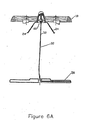
- the reaction torque from the three motors 20 may also assist with the rotation of the saucer 10, since the motors 20 all rotate in the same direction, as viewed from above.
- the propeller inclination may not be necessary when the aerodynamic resistance to rotation is low enough that the motor torque is all that becomes required to rotate the saucer 10.
- a hall effect sensor 80 is positioned on the lower assembly 68 and a pair of reverse rotating magnets 82 are positioned on the upper assembly 62.
- the magnets 82 are arranged such that there is a magnetic null in the center, where the hall effect sensor 80 is located.
- the hall effect sensor 80 moves towards one of the magnets 82, the magnetic field increases towards that magnet and an increasing but opposite field towards the other magnet.
- a hall effect sensor 80 creates and sends a sinusoidal signal to the microprocessor.
- any other form of directional signal could be used, i.e. visible light, radio waves, magnetic field or sound.
- the direction could further be reversed such that the emitter is on the control box and the sensor on the flying saucer.
- the control information could be transmitted with the reference signal and if an onboard power source were included in the rotating toy, the model could be free flying, meaning without a tether 32 or controlled through wireless means.
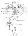
- the rotating toy may be a robot 100.
- the robot 100 has a central body portion 101 that houses the components.
- the robot 100 includes an IR sensor 102 positioned on the top portion thereof, configured to receive a signal from an IR transmitter 104 located on a control box 106.
- the directionality of the IR beam is provided by a restricted view angle of the sensor 102.
- the robot 100 further includes two motors 108 operably connected to a wheel 110 such that when powered the wheels 110 rotate the robot 100 in a predetermined direction.
- the robot 100 also has a power source or battery pack 112.
- the IR transmitter 104 emits a direction code corresponding to the directional inputs from the control box 106.
- a microprocessor 114 on the robot 100 can decode the signal and create cyclic control signals that are out of phase from each other by 180° (since there are two motors 108 the phase is determined from the number of motors 108 divided by 360°).
- the two sine waves would be added to the two motor drive voltages, such that the robot 100 would travel in a direction corresponding to the inputs from the control box 106, in a manner similar discussed above.
Landscapes
- Toys (AREA)
Abstract
Description
Claims (30)
- A rotating toy comprising:a hub having an outer portion rotatably connected to an inner portion;at least three rods extending outwardly from the outer portion and connecting to at least one outer ring, the rods further being positioned at a predetermined offset angle from each other;a rotary device disposed on each rod between the hub and the outer ring, each rotary device includes a motor and a propeller, the propellers being designed to generate lift when rotating by displacing air downwardly, and when the propellers are rotating the motors may generate a reaction torque causing the outer portion of the hub to rotate defining a rotating portion which includes the outer portion of the hub, the rods, the rotary devices and the outer ring;a plurality of legs extending downwardly from the inner portion of the hub to support the rotating toy in an upright configuration when the rotating toy is positioned on a surface, each leg includes a vane protruding outwardly into downwardly displaced air to deflect said displaced air such that the vanes tend to drive the inner portion of the hub in a direction opposite of the outer portion such that when the outer portion is rotating the inner portion is substantially non-rotating defining a non-rotating portion;a means for determining a directional point of reference for the motors when said toy is rotating; anda means for individually controlling the speed of the motors such that the rotating toy may travel in a specified direction.
- The toy of claim 1, wherein the directional point of reference determining means comprises:a pair of IR emitters oppositely positioned on the top portion and the bottom portion of the rotating portion of the toy, the pair of IR emitters being further positioned such that the IR emitters cast IR beams outwardly along the same radial axis; andan IR receiver being placed remotely from the rotating toy and in communication with the controlling means such that upon sensing the IR beam the controlling means may determine the directional point of reference of the three motors.
- The toy of claim 2, wherein the controlling means includes a control box in communication with the rotary devices through a tether that is attached from said control box to the inner portion of the hub.
- The toy of claim 3 further comprising a means to remotely supply a drive voltage through the tether to each motor.
- The toy of claim 4, wherein the control box further includes:wherein the predetermined sinusoidal waves may cause the toy to have a resultant thrust vector in said specified direction.a microprocessor in communication with each motor;a throttle controller in communication with the microprocessor such that the throttle controller may indicate to the microprocessor to increase and decrease the drive voltage to each motor; anda directional controller in communication with the microprocessor such that the directional controller may indicate to the microprocessor to generate and add a predetermined sinusoidal wave to each drive voltage corresponding to a specified direction,
- The toy of claim 5, wherein each predetermined sinusoidal wave is out of phase with one another by the predetermined offset angle.
- The toy of claim 5, wherein each predetermined sinusoidal wave has a beginning phase shift angle determined upon the specified direction.
- The toy of claim 5 further includes a means for sensing when an angle of declination between the tether and the hub is at least a predetermined angle, the sensing means further providing a signal to the microprocessor such that the microprocessor upon receiving said signal may adjust the sinusoidal waves of the motors to move the rotating toy in a direction such that said declination angle becomes less that said predetermined angle.
- The toy of claim 8, wherein the sensing means includes:wherein the microprocessor receiving said signal can determine the orientation of the three motors when said conductive ring contacted the spring and adjust the sinusoidal waves of the motors to move the rotating toy in a direction such that the lower assembly pivots said declination angle becomes less said predetermined angle.an upper assembly attached to the rotating portion of the hub, the upper assembly having an arm extending outwardly and a spring attached to said arm;a lower assembly in communication with the tether and attached to the upper assembly by a swivel such that upper assembly may rotate with the rotating portion and the lower assembly may pivot about the swivel; anda conductive ring positioned about the lower assembly such that when the tether pivots the lower assembly by at least a predetermined angle defined between the lower assembly and the spring, the conductive ring contacts the spring sending a signal through the tether to the microprocessor,
- The toy of claim 5, further including a feed back system such that when the toy moves from a center position to an off center position, the microprocessor may adjust the motors proportionally to the amount the toy has moved from the center position such that the toy has a tendency to return to the center position.
- The toy of claim 10, wherein the feed back system includes:an upper assembly attached to the rotating portion of the hub;a lower assembly in communication with the tether and attached to the upper assembly by a swivel such that upper assembly may rotate with the rotating portion and the lower assembly may pivot about the swivel;a plurality of magnets positioned about the lower assembly and attached to the rotating portion of the hub creating a magnetic null in the center substantially about the lower assembly; anda hall effect sensor attached to the lower assembly and in communication with the microprocessor such that when the tether pivots the lower assembly the hall effect sensor will generate a sinusoidal wave having an amplitude defined as an amount of deflection the hall effect sensor has moved away from the magnetic null and the phase is defined as a direction of the deflection, wherein the microprocessor receiving the signal can adjust the motors to move the rotating toy in a direction opposite of said deflection such that the hall effect sensor is moved towards the magnetic null.
- The toy of claim 8 further comprising:a base unit having an aperture for receiving a portion of the tether and being positioned on the ground such that the rotating toy is restricted to a flying radius defined by the length of the tether between the base unit and the rotating toy.
- The toy of claim 1, wherein the means for determining directional point of reference comprises:an IR emitter being placed remotely from the rotating toy for transmitting an IR beam; anda pair of IR receivers positioned on the top portion and the bottom portion of the rotating portion of the toy, the pair of IR receivers are positioned along the same radial axis, and the IR receivers in communication with the controlling means such that upon sensing the IR beam the controlling means may determine the specific orientation of the three motors.
- The toy of claim 13 further comprising:a means to supply power separately to each motor secured on the rotating toy;a microprocessor in communication with each power supply means and each motor.
- The toy of claim 14 further comprising:throttle controls means in wireless communication with the microprocessor, the throttle controls means for sending a signal to the microprocessor indicating an increase and decrease an amount of power separately supplied to each motor equally; anddirectional controls means in wireless communication with the microprocessor, the directional control means for sending a signal to the microprocessor indicating a direction and a rate in which the toy is to move, wherein the microprocessor receiving said signal may generate and add a sinusoidal wave to each separately supplied power, wherein each sinusoidal wave is offset from each other by the predetermined offset angle and each sinusoidal wave further has a predetermined beginning phase angle such that the motors have a resultant thrust vector in said direction and each sinusoidal wave has an amplitude corresponding to said rate.
- The toy of claim 15, further including a feed back system such that when the toy moves from a center position to an off center position, the microprocessor may adjust the separately supplied power to the motors proportionally to the amount the toy has moved from the center position such that the toy has a tendency to return to the center position.
- The toy of claim 1, wherein each propellers similarly inclined approximately 4°, such that when the rotary devices are operating, the rotating propellers cause the rotating portion to rotate in the opposite direction of the rotating propellers.
- The toy of claim 3, wherein the communication between the tether and rotary devices includes:a circuit board secured to the rotating portion of the hub;four rings mounted on the circuit board; andfour spring loaded brushes mounted on the non-rotating portion of the hub and in communication with control box and the circuit board, each brush corresponding to one of the rings, wherein three of the rings and corresponding brushes are individually in communication with one of the motors and the other ring and corresponding brush is common to the other rings and corresponding brushes.
- A rotating toy comprising:a housing;at least a pair of motors secured to said housing by a predetermined offset angle from each other, each motor rotates a wheel in a direction such that the housing rotates;a power unit supplying a drive voltage to each motor;a microprocessor in communication with the power unit and the motors for controlling the drive voltage to each motor;a sensor positioned on the housing in a restricted view angle in communication with the microprocessor; anda wireless remote transmitter for transmitting a point of reference signal and for transmitting speed and directional control inputs to the microprocessor, wherein the microprocessor upon receiving said signals may determine the orientation of the rotating toy such that the rotating toy may be directed in a direction and rate specified by said speed and directional control inputs.
- The rotating toy of claim 19, wherein the microprocessor upon receiving the speed and directional control inputs from the sensor may generate and add a sinusoidal wave to each drive voltage, wherein each sinusoidal wave is out of phase with each other by the predetermined offset angle.
- The rotating toy of claim 20, wherein each sinusoidal wave has a beginning phase angle based upon the specified direction such that a resultant thrust vector is created in said specified direction, and each sinusoidal wave has an amplitude that is adjusted by the specified rate such that the rate in which the rotating toy moves in the specified direction may be increased and deceased.
- A rotating toy comprising:a hub supporting a plurality of motors positioned at a predetermined offset angle from each other, the motors secured to a means for rotating the toy;a means to provide a drive voltage to each motor;a means to determine the orientation of the motors from a point of reference in a remote non-rotating control box;a means to generate and add a sinusoidal wave to each drive voltage, wherein each sinusoidal wave is out of phase with each other by the predetermined offset angle; anda means to control the amplitude and to shift a beginning phase angle of each sinusoidal wave in response to speed and directional inputs from the remote non-rotating control box, such that the rotating toy may move in a direction referenced from the non-rotating body in response to said speed and directional inputs.
- The rotating toy of claim 22, wherein the motors include a propeller operably connected thereto and orientated such that when the propellers are rotating the rotating toy may lift off the ground.
- The rotating toy of claim 23, wherein:the hub is defined as having an outer portion rotatably connected to an inner portion;the outer portion supports a plurality of rods extending outwardly therefrom substantially along the same plane, the rods further support an outer ring, and each rod supports one of the motors between the outer ring and the outer portion;the inner portion supports a plurality of legs extending downwardly therefrom to support the rotating toy in an upright configuration when is positioned on a surface, each leg includes a vane protruding outwardly such that the air downwardly displaced by the propellers lifting the rotating toy off the ground is deflected, driving the inner portion of the hub in a direction opposite of the outer portion such that when the outer portion is rotating the inner portion is substantially a non-rotating portion; andthe inner portion further supports a tether attached to the inner portion of the hub and to the remote control box, the tether is in communication with the motors and the control means.
- The rotating toy of claim 24, further including a feed back system such that when the rotating toy moves from a center position to an off center position, the control means may adjust the motors proportionally to the amount the rotating toy has moved from the center position such that the rotating toy has a tendency to return to the center position.
- The rotating toy of claim 25, wherein the remote control box includes the means to provide the drive voltage to each motor and the means to control the amplitude and the beginning phase angle of each sinusoidal wave.
- The rotating toy of claim 26, wherein the means to determine the orientation of the motors from a point of reference in the remote control box includes mounting a pair of IR emitters on the rotating toy in a predetermined position relating to a specific orientation of the motors, the IR emitters are mounted such that the IR transmitters rotate along with the motors and transmit an IR beam along the same radial axis, and further mounting an IR sensor on the remote control box such that when the IR beam is received by the IR sensor, said specific orientation of the motors is determined.
- The rotating toy of claim 1, wherein the outer portion is rotatably connected to the inner portion by a substantially frictionless bearing.
- A rotary aircraft comprising:a hub having a plurality of motors positioned at a predetermined offset angle from each other, the motors secured to a means for generating lift and for rotating the rotary aircraft;a means to separately provide power to each motor;a means to determine the orientation of the motors from a point of reference in a remote non-rotating control box; anda means to generate and add a sinusoidal wave to each power means, wherein each sinusoidal wave is out of phase with each other by the predetermined offset angle; anda means to control the amplitude and to shift a beginning phase angle of each sinusoidal wave in response to speed and directional inputs from the remote non-rotating control box, such that the rotary aircraft may move in a direction referenced from the non-rotating body in response to said speed and directional inputs.
- The rotary aircraft of claim 29 further comprising:a means for sending a signal back to the control means when the rotary aircraft moves from a center position to an off center position, wherein the control means may adjust the separately supplied power to the motors proportionally to the amount the toy has moved from the center position such that rotary aircraft has a tendency to return to the center position.
Applications Claiming Priority (2)
| Application Number | Priority Date | Filing Date | Title |
|---|---|---|---|
| US819189 | 2001-03-28 | ||
| US09/819,189 US6688936B2 (en) | 2001-03-28 | 2001-03-28 | Rotating toy with directional vector control |
Publications (2)
| Publication Number | Publication Date |
|---|---|
| EP1245257A2 true EP1245257A2 (en) | 2002-10-02 |
| EP1245257A3 EP1245257A3 (en) | 2003-07-30 |
Family
ID=25227445
Family Applications (1)
| Application Number | Title | Priority Date | Filing Date |
|---|---|---|---|
| EP02006798A Withdrawn EP1245257A3 (en) | 2001-03-28 | 2002-03-25 | Rotating toy with directional vector control |
Country Status (5)
| Country | Link |
|---|---|
| US (1) | US6688936B2 (en) |
| EP (1) | EP1245257A3 (en) |
| JP (1) | JP2002292153A (en) |
| CN (2) | CN2524808Y (en) |
| TW (1) | TW581707B (en) |
Cited By (10)
| Publication number | Priority date | Publication date | Assignee | Title |
|---|---|---|---|---|
| CN102350059A (en) * | 2011-08-29 | 2012-02-15 | 广东骅威玩具工艺股份有限公司 | Electromagnetic helm gear |
| WO2014055899A1 (en) * | 2012-10-05 | 2014-04-10 | Qfo Labs, Inc. | Remote-control flying copter and method |
| ITTO20130543A1 (en) * | 2013-06-28 | 2014-12-29 | Quater Paolo Bellezza | MULTIROST AIRCRAFT |
| WO2015023992A1 (en) * | 2013-08-15 | 2015-02-19 | Traxxas Lp | Rotorcraft with integrated light pipe support members |
| EP2942094A1 (en) | 2014-05-06 | 2015-11-11 | Parrot | Rotary-wing drone such as a quadcopter, with removable bumpers for propeller protection |
| USD827723S1 (en) | 2015-09-28 | 2018-09-04 | Traxxas Lp | Quadrotor model helicopter |
| USD827724S1 (en) | 2015-09-28 | 2018-09-04 | Traxxas Lp | Set of supporting arms for a quadrotor model helicopter |
| CN108674628A (en) * | 2018-04-18 | 2018-10-19 | 佛山世寰智能科技有限公司 | A kind of loop configuration tailstock formula vertical take-off and landing unmanned aerial vehicle |
| US10258888B2 (en) | 2015-11-23 | 2019-04-16 | Qfo Labs, Inc. | Method and system for integrated real and virtual game play for multiple remotely-controlled aircraft |
| US11141673B1 (en) | 2016-09-28 | 2021-10-12 | Traxxas Lp | Model rotorcraft with light pipe support members |
Families Citing this family (87)
| Publication number | Priority date | Publication date | Assignee | Title |
|---|---|---|---|---|
| US7497759B1 (en) * | 2001-03-28 | 2009-03-03 | Steven Davis | Directionally controllable, self-stabilizing, rotating flying vehicle |
| US8113905B2 (en) * | 2001-03-28 | 2012-02-14 | Steven Davis | Directionally controllable flying vehicle and a propeller mechanism for accomplishing the same |
| US7255623B2 (en) * | 2001-03-28 | 2007-08-14 | Steven Davis | Self-stabilizing rotating toy |
| US6843699B2 (en) * | 2001-03-28 | 2005-01-18 | Steven Davis | Flying toy |
| WO2004101357A2 (en) | 2002-08-30 | 2004-11-25 | Qaxu Technology Inc. | Homeostatic flying hovercraft |
| USD496695S1 (en) | 2003-03-14 | 2004-09-28 | Steven Davis | Flying toy |
| USD494640S1 (en) | 2003-04-23 | 2004-08-17 | Leynian Ltd. Co. | Flying toy |
| US6811460B1 (en) * | 2003-08-05 | 2004-11-02 | Leynian Ltd. Co. | Flying toy vehicle |
| US6960112B2 (en) * | 2003-08-12 | 2005-11-01 | Mattel, Inc. | Airfoil blade with cushioned edge for powered toy aircraft |
| US7331838B2 (en) * | 2004-04-16 | 2008-02-19 | Jasman Asia Ltd. | Propeller impact protector and model flying airplane incorporating same |
| US7946526B2 (en) * | 2004-11-05 | 2011-05-24 | Nachman Zimet | Rotary-wing vehicle system |
| US7628671B2 (en) * | 2004-11-26 | 2009-12-08 | Silverlit Toys Manufactory Ltd. | Programmable flying object |
| US7407424B2 (en) * | 2005-01-10 | 2008-08-05 | Silverlit Toys Manufactory, Ltd. | Spatial navigation system and method for programmable flying objects |
| JP4289677B2 (en) * | 2005-02-04 | 2009-07-01 | 株式会社 一歩 | Mobile toy using magnetic force |
| US7275973B2 (en) * | 2005-06-03 | 2007-10-02 | Mattel, Inc. | Toy aircraft |
| JP2007130146A (en) * | 2005-11-09 | 2007-05-31 | Taiyo Kogyo Kk | Radio-controlled flying toy |
| US20070215750A1 (en) * | 2005-11-18 | 2007-09-20 | Michael Shantz | Radio controlled helicopter |
| US7883392B2 (en) | 2008-08-04 | 2011-02-08 | Silverlit Toys Manufactory Ltd. | Toy helicopter |
| US8002604B2 (en) * | 2006-01-19 | 2011-08-23 | Silverlit Limited | Remote controlled toy helicopter |
| US8357023B2 (en) * | 2006-01-19 | 2013-01-22 | Silverlit Limited | Helicopter |
| BE1016960A3 (en) | 2006-01-19 | 2007-11-06 | Rostyne Alexander Jozef Magdal | IMPROVED HELICOPTER. |
| US20090047861A1 (en) * | 2006-01-19 | 2009-02-19 | Silverlit Toys Manufactory Ltd. | Remote controlled toy helicopter |
| US7815482B2 (en) * | 2006-01-19 | 2010-10-19 | Silverlit Toys Manufactory, Ltd. | Helicopter |
| US8133089B2 (en) | 2006-05-03 | 2012-03-13 | Mattel, Inc. | Modular toy aircraft with capacitor power sources |
| US7811150B2 (en) | 2006-05-03 | 2010-10-12 | Mattel, Inc. | Modular toy aircraft |
| JP2009541121A (en) * | 2006-06-26 | 2009-11-26 | ヴィゲリヒ,ブルクハルト | Flight equipment |
| US7614931B2 (en) * | 2006-09-20 | 2009-11-10 | Mattel, Inc. | Toy vehicle track set |
| IL179666A0 (en) * | 2006-11-28 | 2007-05-15 | Yefim Kereth | Torque-balancing differential mechanism |
| US8109802B2 (en) | 2007-09-15 | 2012-02-07 | Mattel, Inc. | Toy helicopter having a stabilizing bumper |
| US8118634B2 (en) * | 2008-01-04 | 2012-02-21 | William Mark Corporation | Method and apparatus for near-invisible tethers |
| USD631922S1 (en) | 2008-02-06 | 2011-02-01 | Mattel, Inc. | Remote control unit |
| US7798883B2 (en) * | 2008-02-25 | 2010-09-21 | Spin Master Ltd. | Acrobatic rotary-wing toy helicopter |
| FR2938774A1 (en) * | 2008-11-27 | 2010-05-28 | Parrot | DEVICE FOR CONTROLLING A DRONE |
| US20100224723A1 (en) * | 2009-03-03 | 2010-09-09 | Jacob Apkarian | Aerial vehicle |
| GB0905027D0 (en) * | 2009-03-24 | 2009-05-06 | Allen Technology Ltd | Flying apparatus |
| JP2011046355A (en) * | 2009-08-28 | 2011-03-10 | Kitakyushu Foundation For The Advancement Of Industry Science & Technology | Flying body |
| FR2952787B1 (en) * | 2009-11-13 | 2012-07-27 | Parrot | ELECTRONIC NAVIGATON CARD HOLDER FOR ROTARY SAIL DRONE |
| CN101732873B (en) * | 2009-12-31 | 2014-12-10 | 马宇尘 | Aircraft type hand-held terminal for responding to user requirements |
| USD664214S1 (en) * | 2010-04-16 | 2012-07-24 | Hobbyengine Model Ltd. | Toy radio control UFO |
| US20120190268A1 (en) * | 2010-06-22 | 2012-07-26 | Raaid Fouad Mustafa | Flying device |
| US20120127012A1 (en) * | 2010-11-24 | 2012-05-24 | Samsung Electronics Co., Ltd. | Determining user intent from position and orientation information |
| CN102092473A (en) * | 2011-01-25 | 2011-06-15 | 凌强 | Multi-rotor craft and method thereof |
| FR2972364B1 (en) * | 2011-03-08 | 2014-06-06 | Parrot | METHOD FOR CONTROLLING FOLLOWING A CURVED TURNING OF A MULTI - ROTOR ROTOR SAILING DRONE. |
| US20120270466A1 (en) * | 2011-04-25 | 2012-10-25 | Spin Master Ltd. | System for automatically tracking a moving toy vehicle |
| WO2012160719A1 (en) * | 2011-05-25 | 2012-11-29 | 株式会社エムエスシー | Flying disk |
| USD677739S1 (en) | 2011-07-21 | 2013-03-12 | John J. Wojtaszek | Star-shaped flying ring |
| KR101267863B1 (en) | 2011-09-21 | 2013-05-27 | 주식회사 바이로봇 | vertical takeoff and landing aircraft |
| CN102688602B (en) * | 2012-06-14 | 2013-11-27 | 北京理工大学 | Rotary missile rudder based on polar coordinate system control |
| US8639400B1 (en) * | 2012-09-26 | 2014-01-28 | Silverlit Limited | Altitude control of an indoor flying toy |
| US20140231582A1 (en) * | 2012-10-03 | 2014-08-21 | Sean Headrick | Methods and Systems of Constructing a Multi Rotor Aircraft Fuselage |
| DE202013012546U1 (en) | 2012-11-15 | 2017-05-30 | SZ DJI Technology Co., Ltd. | Unmanned aerial vehicle with multiple rotors |
| CN108516082B (en) * | 2013-06-09 | 2021-06-18 | 瑞士苏黎世联邦理工学院 | Controlled flight of a multirotor experiencing a failure affecting the effector |
| CN105407993B (en) * | 2013-07-01 | 2017-08-25 | 安泰克私人有限公司 | Air force lifting device |
| DE102013225304B4 (en) * | 2013-12-09 | 2021-06-24 | Meteomatics Gmbh | Aircraft |
| CN104008687B (en) * | 2014-05-20 | 2017-12-12 | 万金芬 | A kind of electronic building blocks and its circuit based on infrared electro technology |
| US10358214B2 (en) * | 2015-01-04 | 2019-07-23 | Hangzhou Zero Zro Technology Co., Ltd. | Aerial vehicle and method of operation |
| US10126745B2 (en) | 2015-01-04 | 2018-11-13 | Hangzhou Zero Zero Technology Co., Ltd. | System and method for automated aerial system operation |
| US9836053B2 (en) | 2015-01-04 | 2017-12-05 | Zero Zero Robotics Inc. | System and method for automated aerial system operation |
| US10220954B2 (en) | 2015-01-04 | 2019-03-05 | Zero Zero Robotics Inc | Aerial system thermal control system and method |
| US10719080B2 (en) | 2015-01-04 | 2020-07-21 | Hangzhou Zero Zero Technology Co., Ltd. | Aerial system and detachable housing |
| CN106143883A (en) * | 2015-03-10 | 2016-11-23 | 周利英 | Gyroplane |
| US9586158B2 (en) | 2015-03-17 | 2017-03-07 | William Mark Corporation | Telekinesis light wand |
| US10315759B2 (en) * | 2015-04-04 | 2019-06-11 | California Institute Of Technology | Multi-rotor vehicle with yaw control and autorotation |
| WO2016163482A1 (en) * | 2015-04-07 | 2016-10-13 | 株式会社日本自動車部品総合研究所 | Mobile unit |
| US9650134B2 (en) * | 2015-06-05 | 2017-05-16 | Dana R. CHAPPELL | Unmanned aerial rescue system |
| US20170029103A1 (en) * | 2015-07-28 | 2017-02-02 | Inventec Appliances (Pudong) Corporation | Unmanned vehicle |
| CN106628134B (en) * | 2015-10-28 | 2019-11-05 | 顾晓伟 | A kind of rotor flight device and its control method |
| TWI581841B (en) | 2015-10-30 | 2017-05-11 | 財團法人工業技術研究院 | Separable flight device |
| USD789411S1 (en) * | 2015-11-18 | 2017-06-13 | SZ DJI Technology Co., Ltd. | Display screen or portion thereof with animated graphical user interface |
| CA173835S (en) * | 2016-02-26 | 2017-08-15 | Powervision Robot Inc | Pedestal of unmanned aerial vehicle |
| WO2017187275A2 (en) | 2016-04-24 | 2017-11-02 | Hangzhou Zero Zero Technology Co., Ltd. | Aerial system propulsion assembly and method of use |
| US10737786B2 (en) | 2016-05-13 | 2020-08-11 | Bell Helicopter Textron Inc. | Distributed propulsion system for vertical take off and landing closed wing aircraft |
| USD798795S1 (en) * | 2016-05-13 | 2017-10-03 | Bell Helicopter Textron Inc. | Ring wing and spokes for a closed wing aircraft |
| USD798794S1 (en) * | 2016-05-13 | 2017-10-03 | Bell Helicopter Textron Inc. | Closed wing aircraft |
| USD796414S1 (en) * | 2016-05-13 | 2017-09-05 | Bell Helicopter Textron Inc. | Sinusoidal circular wing and spokes for a closed wing aircraft |
| US10331218B2 (en) * | 2016-09-15 | 2019-06-25 | Real Simple Ideas, Llc | Gyroscope motion feedback device |
| US10067513B2 (en) | 2017-01-23 | 2018-09-04 | Hangzhou Zero Zero Technology Co., Ltd | Multi-camera system and method of use |
| CN107233713B (en) * | 2017-06-30 | 2022-10-25 | 华南理工大学 | Flying disc launching mechanism capable of controlling rotating speed and flying track |
| CN110214111A (en) * | 2017-12-29 | 2019-09-06 | 深圳市钛翼科技有限公司 | Spinning Luminous Aircraft |
| US11712637B1 (en) | 2018-03-23 | 2023-08-01 | Steven M. Hoffberg | Steerable disk or ball |
| US10669020B2 (en) * | 2018-04-02 | 2020-06-02 | Anh VUONG | Rotorcraft with counter-rotating rotor blades capable of simultaneously generating upward lift and forward thrust |
| USD892225S1 (en) | 2020-03-10 | 2020-08-04 | DongGuan Tesmai Electronic Technology Co., LTD | Toy aircraft |
| USD891522S1 (en) | 2020-04-03 | 2020-07-28 | DongGuan Tesmai Electronic Technology Co., LTD | Toy aircraft |
| USD1101613S1 (en) * | 2022-04-04 | 2025-11-11 | Richard Lee Armstrong | Cargo spaceship |
| WO2024035714A1 (en) * | 2022-08-09 | 2024-02-15 | Pete Bitar | Compact and lightweight drone delivery device called an arcspear electric jet drone system having an electric ducted air propulsion system and being relatively difficult to track in flight |
| USD1084146S1 (en) * | 2024-03-20 | 2025-07-15 | Shenzhen Yangri Electronics Co., Ltd. | Toy rocket |
| WO2026077554A1 (en) * | 2024-10-07 | 2026-04-16 | Lego A/S | Motor assemblies for toys or educational devices |
Family Cites Families (23)
| Publication number | Priority date | Publication date | Assignee | Title |
|---|---|---|---|---|
| US3568358A (en) * | 1968-10-04 | 1971-03-09 | Joel T Bruce | Flying saucer toy |
| US3549109A (en) | 1969-03-05 | 1970-12-22 | James B Gilstrap | Optical flight control system |
| US3727055A (en) | 1970-09-24 | 1973-04-10 | Gen Electric | Optical positioning system |
| US4065873A (en) * | 1976-08-30 | 1978-01-03 | Robert Alexander Jones | Flying saucer toy |
| US4452174A (en) * | 1982-09-30 | 1984-06-05 | Fedder Richard C | Toner concentration sensor assembly for electro-photographic apparatus |
| DE3606399A1 (en) | 1986-02-27 | 1987-09-03 | Messerschmitt Boelkow Blohm | MEASURING DEVICE FOR DETERMINING THE POSITION OF AN OBJECT |
| JPS63186496U (en) | 1987-05-22 | 1988-11-30 | ||
| JPH066199B2 (en) * | 1988-02-05 | 1994-01-26 | 株式会社キーエンス | Vertical takeoff and landing toys |
| US4931028A (en) | 1988-08-15 | 1990-06-05 | Jaeger Hugh D | Toy blimp |
| FR2636303B1 (en) | 1988-09-14 | 1992-05-07 | Telecommunications Sa | ASSISTANCE SYSTEM FOR THE DECKING OF AIRCRAFT HAVING A STATIONARY FLIGHT ON A SHIP PLATFORM |
| JPH03289984A (en) * | 1990-04-06 | 1991-12-19 | Yoichi Endo | Flying toy |
| US5082079A (en) * | 1990-05-04 | 1992-01-21 | Aerovironment, Inc. | Passively stable hovering system |
| JPH074452B2 (en) * | 1990-05-17 | 1995-01-25 | ジャルデータ通信株式会社 | Radio-controlled flying vehicle |
| US5297759A (en) | 1992-04-06 | 1994-03-29 | Neil Tilbor | Rotary aircraft passively stable in hover |
| US5407151A (en) | 1993-03-08 | 1995-04-18 | Singhal; Tara C. | Model plane flight control |
| JPH07163765A (en) | 1993-12-16 | 1995-06-27 | B I:Kk | Remote control toy |
| US5429542A (en) | 1994-04-29 | 1995-07-04 | Britt, Jr.; Harold D. | Helium-filled remote-controlled saucer toy |
| US5723928A (en) * | 1994-09-30 | 1998-03-03 | Toyoda Koki Kabushiki Kaisha | Induction motor and method of adjusting power factor of the same |
| US5672086A (en) | 1994-11-23 | 1997-09-30 | Dixon; Don | Aircraft having improved auto rotation and method for remotely controlling same |
| US5634839A (en) | 1994-11-23 | 1997-06-03 | Donald Dixon | Toy aircraft and method for remotely controlling same |
| US5971320A (en) | 1997-08-26 | 1999-10-26 | Jermyn; Phillip Matthew | Helicopter with a gyroscopic rotor and rotor propellers to provide vectored thrust |
| EP1049964B1 (en) * | 1997-11-27 | 2002-03-13 | Solar & Robotics | Improvements to mobile robots and their control system |
| FR2809026B1 (en) * | 2000-05-18 | 2003-05-16 | Philippe Louvel | ELECTRIC FLYING SAUCER, PILOTED AND REMOTELY POWERED |
-
2001
- 2001-03-28 US US09/819,189 patent/US6688936B2/en not_active Expired - Fee Related
-
2002
- 2002-02-10 CN CN02206423U patent/CN2524808Y/en not_active Expired - Fee Related
- 2002-02-10 CN CN02105105.4A patent/CN1183987C/en not_active Expired - Fee Related
- 2002-03-08 JP JP2002064301A patent/JP2002292153A/en active Pending
- 2002-03-25 EP EP02006798A patent/EP1245257A3/en not_active Withdrawn
- 2002-03-26 TW TW091105956A patent/TW581707B/en not_active IP Right Cessation
Cited By (19)
| Publication number | Priority date | Publication date | Assignee | Title |
|---|---|---|---|---|
| CN102350059A (en) * | 2011-08-29 | 2012-02-15 | 广东骅威玩具工艺股份有限公司 | Electromagnetic helm gear |
| US10307667B2 (en) | 2012-10-05 | 2019-06-04 | Qfo Labs, Inc. | Remote-control flying craft |
| WO2014055899A1 (en) * | 2012-10-05 | 2014-04-10 | Qfo Labs, Inc. | Remote-control flying copter and method |
| US9004973B2 (en) | 2012-10-05 | 2015-04-14 | Qfo Labs, Inc. | Remote-control flying copter and method |
| US9011250B2 (en) | 2012-10-05 | 2015-04-21 | Qfo Labs, Inc. | Wireless communication system for game play with multiple remote-control flying craft |
| ITTO20130543A1 (en) * | 2013-06-28 | 2014-12-29 | Quater Paolo Bellezza | MULTIROST AIRCRAFT |
| WO2014207732A1 (en) * | 2013-06-28 | 2014-12-31 | Paolo Bellezza Quater | A multi-rotor aircraft |
| WO2015023992A1 (en) * | 2013-08-15 | 2015-02-19 | Traxxas Lp | Rotorcraft with integrated light pipe support members |
| DE112014003752B4 (en) * | 2013-08-15 | 2020-08-27 | Traxxas Lp | Rotary wing aircraft with integrated light guide support elements |
| US9221539B2 (en) | 2013-08-15 | 2015-12-29 | Traxxas Lp | Rotorcraft with integrated light pipe support members |
| US9938009B2 (en) | 2013-08-15 | 2018-04-10 | Traxxas Lp | Rotorcraft with integrated light pipe support members |
| FR3020763A1 (en) * | 2014-05-06 | 2015-11-13 | Parrot | QUADRICOPTERE TYPE ROTARY SAILING WHEEL HAVING REMOVABLE PROPERTY PROTECTION BUMPERS |
| EP2942094A1 (en) | 2014-05-06 | 2015-11-11 | Parrot | Rotary-wing drone such as a quadcopter, with removable bumpers for propeller protection |
| USD827724S1 (en) | 2015-09-28 | 2018-09-04 | Traxxas Lp | Set of supporting arms for a quadrotor model helicopter |
| USD827723S1 (en) | 2015-09-28 | 2018-09-04 | Traxxas Lp | Quadrotor model helicopter |
| US10258888B2 (en) | 2015-11-23 | 2019-04-16 | Qfo Labs, Inc. | Method and system for integrated real and virtual game play for multiple remotely-controlled aircraft |
| US11141673B1 (en) | 2016-09-28 | 2021-10-12 | Traxxas Lp | Model rotorcraft with light pipe support members |
| CN108674628A (en) * | 2018-04-18 | 2018-10-19 | 佛山世寰智能科技有限公司 | A kind of loop configuration tailstock formula vertical take-off and landing unmanned aerial vehicle |
| CN108674628B (en) * | 2018-04-18 | 2021-07-23 | 佛山世寰智能科技有限公司 | An annular structure tailstock vertical take-off and landing unmanned aerial vehicle |
Also Published As
| Publication number | Publication date |
|---|---|
| JP2002292153A (en) | 2002-10-08 |
| EP1245257A3 (en) | 2003-07-30 |
| CN2524808Y (en) | 2002-12-11 |
| US6688936B2 (en) | 2004-02-10 |
| CN1183987C (en) | 2005-01-12 |
| CN1370615A (en) | 2002-09-25 |
| TW581707B (en) | 2004-04-01 |
| US20020142699A1 (en) | 2002-10-03 |
Similar Documents
| Publication | Publication Date | Title |
|---|---|---|
| US6688936B2 (en) | Rotating toy with directional vector control | |
| US7794302B2 (en) | Directionally controllable, self-stabilizing, rotating flying vehicle | |
| US5971320A (en) | Helicopter with a gyroscopic rotor and rotor propellers to provide vectored thrust | |
| US9904292B2 (en) | Method for operating a radio-controlled flying hovercraft | |
| US8113905B2 (en) | Directionally controllable flying vehicle and a propeller mechanism for accomplishing the same | |
| US8500507B2 (en) | Directionally controllable flying vehicle and a propeller mechanism for accomplishing the same | |
| US10307667B2 (en) | Remote-control flying craft | |
| US7255623B2 (en) | Self-stabilizing rotating toy | |
| US6899586B2 (en) | Self-stabilizing rotating toy | |
| WO2009154044A1 (en) | Helicopter toy | |
| CN105116933B (en) | A kind of unmanned vehicle and the method for preventing unmanned vehicle disengaging control area | |
| JP2006027588A (en) | Small flight equipment | |
| JP2008093204A (en) | Counter-rotating rotorcraft | |
| US20100243793A1 (en) | Flying apparatus | |
| CN215232100U (en) | Toy aircraft | |
| WO2007146563A2 (en) | Directionally controllable, self-stabilizing, rotating flying vehicle | |
| US20090068919A1 (en) | Flying toy apparatus | |
| JP2560919Y2 (en) | Attitude control device for flying toys |
Legal Events
| Date | Code | Title | Description |
|---|---|---|---|
| PUAI | Public reference made under article 153(3) epc to a published international application that has entered the european phase |
Free format text: ORIGINAL CODE: 0009012 |
|
| AK | Designated contracting states |
Kind code of ref document: A2 Designated state(s): AT BE CH CY DE DK ES FI FR GB GR IE IT LI LU MC NL PT SE TR |
|
| AX | Request for extension of the european patent |
Free format text: AL;LT;LV;MK;RO;SI |
|
| PUAL | Search report despatched |
Free format text: ORIGINAL CODE: 0009013 |
|
| AK | Designated contracting states |
Designated state(s): AT BE CH CY DE DK ES FI FR GB GR IE IT LI LU MC NL PT SE TR |
|
| AX | Request for extension of the european patent |
Extension state: AL LT LV MK RO SI |
|
| RIC1 | Information provided on ipc code assigned before grant |
Ipc: 7A 63H 27/127 B Ipc: 7A 63H 27/04 A |
|
| 17P | Request for examination filed |
Effective date: 20031008 |
|
| AKX | Designation fees paid |
Designated state(s): AT BE CH CY DE DK ES FI FR GB GR IE IT LI LU MC NL PT SE TR |
|
| GRAP | Despatch of communication of intention to grant a patent |
Free format text: ORIGINAL CODE: EPIDOSNIGR1 |
|
| STAA | Information on the status of an ep patent application or granted ep patent |
Free format text: STATUS: THE APPLICATION IS DEEMED TO BE WITHDRAWN |
|
| 18D | Application deemed to be withdrawn |
Effective date: 20080411 |