EP1246415A2 - Method and apparatus for communications traffic engineering - Google Patents
Method and apparatus for communications traffic engineering Download PDFInfo
- Publication number
- EP1246415A2 EP1246415A2 EP02252264A EP02252264A EP1246415A2 EP 1246415 A2 EP1246415 A2 EP 1246415A2 EP 02252264 A EP02252264 A EP 02252264A EP 02252264 A EP02252264 A EP 02252264A EP 1246415 A2 EP1246415 A2 EP 1246415A2
- Authority
- EP
- European Patent Office
- Prior art keywords
- traffic
- trunk
- node
- network
- lsp
- Prior art date
- Legal status (The legal status is an assumption and is not a legal conclusion. Google has not performed a legal analysis and makes no representation as to the accuracy of the status listed.)
- Granted
Links
- 238000000034 method Methods 0.000 title claims abstract description 106
- 238000004891 communication Methods 0.000 title description 23
- 229920006008 lipopolysaccharide Polymers 0.000 claims 1
- 230000008569 process Effects 0.000 description 86
- 208000027744 congestion Diseases 0.000 description 43
- 238000013461 design Methods 0.000 description 20
- 238000005516 engineering process Methods 0.000 description 13
- 238000010586 diagram Methods 0.000 description 10
- 238000011156 evaluation Methods 0.000 description 10
- 239000013598 vector Substances 0.000 description 10
- 238000009826 distribution Methods 0.000 description 5
- 230000006870 function Effects 0.000 description 5
- 238000001514 detection method Methods 0.000 description 4
- 238000007726 management method Methods 0.000 description 4
- 230000009467 reduction Effects 0.000 description 4
- 230000032258 transport Effects 0.000 description 3
- 230000007246 mechanism Effects 0.000 description 2
- 238000012986 modification Methods 0.000 description 2
- 230000004048 modification Effects 0.000 description 2
- 238000012384 transportation and delivery Methods 0.000 description 2
- 239000000470 constituent Substances 0.000 description 1
- 238000010276 construction Methods 0.000 description 1
- 230000001934 delay Effects 0.000 description 1
- 230000000694 effects Effects 0.000 description 1
- 238000012854 evaluation process Methods 0.000 description 1
- 230000014509 gene expression Effects 0.000 description 1
- 230000003116 impacting effect Effects 0.000 description 1
- 230000000977 initiatory effect Effects 0.000 description 1
- 239000011159 matrix material Substances 0.000 description 1
- 238000005259 measurement Methods 0.000 description 1
- 230000006855 networking Effects 0.000 description 1
- 230000000737 periodic effect Effects 0.000 description 1
- 230000002093 peripheral effect Effects 0.000 description 1
- 238000012545 processing Methods 0.000 description 1
- 238000011084 recovery Methods 0.000 description 1
- 238000013468 resource allocation Methods 0.000 description 1
- 239000000126 substance Substances 0.000 description 1
- 238000012360 testing method Methods 0.000 description 1
Images


Classifications
-
- H—ELECTRICITY
- H04—ELECTRIC COMMUNICATION TECHNIQUE
- H04L—TRANSMISSION OF DIGITAL INFORMATION, e.g. TELEGRAPHIC COMMUNICATION
- H04L45/00—Routing or path finding of packets in data switching networks
- H04L45/50—Routing or path finding of packets in data switching networks using label swapping, e.g. multi-protocol label switch [MPLS]
-
- H—ELECTRICITY
- H04—ELECTRIC COMMUNICATION TECHNIQUE
- H04L—TRANSMISSION OF DIGITAL INFORMATION, e.g. TELEGRAPHIC COMMUNICATION
- H04L45/00—Routing or path finding of packets in data switching networks
-
- H—ELECTRICITY
- H04—ELECTRIC COMMUNICATION TECHNIQUE
- H04L—TRANSMISSION OF DIGITAL INFORMATION, e.g. TELEGRAPHIC COMMUNICATION
- H04L47/00—Traffic control in data switching networks
- H04L47/10—Flow control; Congestion control
-
- H—ELECTRICITY
- H04—ELECTRIC COMMUNICATION TECHNIQUE
- H04L—TRANSMISSION OF DIGITAL INFORMATION, e.g. TELEGRAPHIC COMMUNICATION
- H04L47/00—Traffic control in data switching networks
- H04L47/10—Flow control; Congestion control
- H04L47/12—Avoiding congestion; Recovering from congestion
- H04L47/122—Avoiding congestion; Recovering from congestion by diverting traffic away from congested entities
Definitions
- This invention relates to a method and apparatus for engineering communications traffic.
- OSPF Open Shortest Path First
- OSPF Open Shortest Path First
- This invention provides systems and methods for selectively off-loading appropriate amounts of traffic from congested sub-regions of a network to more lightly loaded sub-regions of the network by applying explicitly routed label switching paths (ER-LSP) of a label switching technology, hereinafter referred to as Multiprotocol Label Switching (MPLS) technology.
- ERP explicitly routed label switching paths
- MPLS Multiprotocol Label Switching
- traffic trunks containing lightly loaded links can be selected and traffic can be rerouted to the lightly loaded links with an uneven load-splitting ratio to alleviate congestion.
- traffic is rapidly redistributed to ensure that every link's utilization, within a given path, is below designated maximum values. Consequently, MPLS technology permits the effective utilization of network resources.
- Multiprotocol Label Switching (MPLS) technology mitigates many of the shortcomings of conventional congestion management schemes by permitting the selective off-loading of appropriate amounts of traffic from congested paths of sub-regions of a network to more lightly loaded paths of sub-regions of the network in a rapid manner.
- MPLS Multiprotocol Label Switching
- the explicit routing label switching paths (ER-LSP) capabilities of MPLS technology are used to enable "uneven" load-splitting of traffic over arbitrary paths to reroute traffic in a more efficient manner.
- LSPs primary Label Switching Paths
- alternate LSPs the paths designated for rerouting around an element failure or congestion in a primary LSP.
- This invention is capable of generating primary LSP templates and alternate LSP templates for network traffic management.
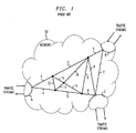
- Fig. 1 illustrates a simple network 50, ingressing and egressing routers A, B, C and links 1-14, with traffic flow routed in a conventional OSPF manner.
- traffic in a network can be defined as being associated with a traffic trunk, where the traffic trunk is an aggregated traffic stream primarily defined by its ingress and egress routers. That is, traffic in a traffic trunk may be associated with a source address corresponding to an ingress router and a destination address corresponding to an egress router. Therefore, the term traffic trunk can be used to generically refer to the aggregated traffic streams that enter or exit a network.
- Table 1 demonstrates the various traffic in the simple network 50 and the links comprising the paths used in a conventional OSPF routing scheme.
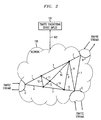
- Fig. 2 illustrates a simple exemplary network 105 using an exemplary embodiment of a Multiprotocol Label Switching traffic engineering device 100.
- the exemplary traffic engineering device will reroute traffic from the congested links to other less congested links along primary LSPs and alternate LSPs.
- Table 2 provides, for example, exemplary paths for traffic destined to router C from router A (i.e., traffic trunk A ⁇ C).
- Primary LSP(s) Alternate LSP(s) Egressing Router Paths from Paths from Originating Originating Router A Router A C 1-11-14-6 - 4-12-2-8
- determination of the primary and alternate LSPs is based, among other factors, as further discussed below, on evaluating in a sorted order the various traffic trunks in the network 105 and their respective traffic contributions to one or more congested links. Accordingly, as these contributing traffic trunks - sorted in order of greatest to least traffic contributions - to the one or more congested links - arc computationally removed from the network, it is apparent that the congested links will experience a reduction in their traffic flow. Correspondingly, the formerly congested links may continue to provide traffic paths, but at non-congested levels.
- the traffic engineering device 100 is connected to a network 105 via a bi-directional link 102.
- the network 105 can be one or more networks containing typical network resources such as routers, traffic trunks, links, packet and switch based networks, servers, terminals, traffic nodes, etc. (all not shown).
- Each network resource in the network 105 is capable of transmitting or receiving data from each other network resource in the network 105, and may possess additional network or non-network related capabilities, as desired.
- the network 105 may be connected to other external devices, systems, or networks (not shown) and facilitates traffic via traffic routers A, B, and C, for example.
- the network 105 can be any system containing communications capabilities between two or more devices or systems.
- the network 105 can operate as a digital or analog communication system, in packet or switched mode, wireless or wired, and can facilitate communication between any known or yet known device capable of communicating information or the like to any other device connected to the network 105.
- Traffic streams external to the network 105, enter or exit the network 105 via traffic routers A, B, and C. Since the network 105 contains various internal links, for example, 1-13, between each of the various traffic routers A, B, and C, the traffic engineering device 100, by determining the paths taken by traffic within the network 105, can control the traffic flow between the ingressing and egressing portions of the traffic - i.e., routers A, B, and C.
- traffic trunks are typically characterized by ingress routers that control the traffic streams as they enter a network and egress routers that control the traffic streams as they exit a network. It is further appreciated that the traffic streams from the traffic trunks may traverse various network resources such as links, servers, other traffic trunks, communication-related or non-communication-related devices, etc. Since traffic streams can be characterized by traffic trunks, it is apparent that traffic trunks may traverse several tens, hundreds, thousands or more paths that are interconnected or independent of each other. Therefore, each path or network resource internal to an exemplary MPLS-controlled network 105 that is connected by a traffic trunk may be controlled by the traffic engineering device 100 to alter the paths of the constituent traffic flow.
- congested links in the network 105 that are traversed by traffic data of a traffic trunk can be "uncongested" by appropriately controlling the trunk(s) to reroute traffic away from the congested links.
- the exemplary embodiments of this invention describe systems and methods that control traffic trunks, it is apparent that the exemplary embodiments of this invention may be applied to trafficking devices other than those listed above that provide similar or related capabilities to traffic control.
- Communication paths within the network 105 can occasionally become congested or fail. Upon such events, the network 105 can quickly initiate a recovery by establishing new internal communication paths within the network 105.
- the restoration process starts as the traffic engineering device 100 detects a problem using well known fault detection devices (not shown). Upon detection of a problem, the traffic engineering device 100 reroutes communication from the congested or failed internal communication path to one or more new communication paths within the network 105 - as illustrated, for example, in Table 2 - thereby maintaining proper traffic flow.
- the re-routing of the communication method is initiated or controlled by the traffic engineering device 100 connected to the network 105 via communication/control link 102.
- Fig. 2 illustrates routers A, B, and C, as concerning traffic streams entering/exiting the network 105
- other traffic trunks (not shown) interior to the network 105 may control traffic streams inside the network 105.
- the traffic streams egressing or ingressing the network 105 or interior traffic streams within the network 105 may connect to one or more such networks, such as other MPLS-controlled networks, the Internet, a telephone network (e.g., local and/or long distance), or other wired or wireless networks, for example.
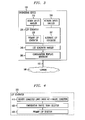
- Fig. 3 is a block diagram illustrating exemplary elements of an exemplary traffic engineering device 100, implementing an MPLS technology.
- the exemplary traffic engineering device 100 contains a design inputs handler 310, a network inputs handler 320, a LSP generator 330, a list generator handler 340, and a configuration template generator 350 connected to a network 105 via link 102.
- the design inputs handler 310 contains MPLS system design parameters and processes these parameters for use in generating MPLS path routing commands or information for subsequent handling.
- design inputs handler 310 contains a parameter, UN max , which is the maximum targeted utilization, under normal conditions, designated for every link in the network 105.
- UN max is defined as a fixed network parameter having the relationship UN max ⁇ (volume of traffic in link)/(speed of link).
- Other design parameters - such as, for example, the maximum targeted utilization under a single failure ( UF max ), the maximum number of multiple primary LSPs ( Max Prim ) , and the maximum number of multiple alternate LSPs ( Max Alt ) - may also be contained in the design inputs handler 310.
- the network inputs handler 320 operates similarly to the design inputs handler 310; however, the network inputs handler 320 contains network-related information, such as, for example, the network topology, routing protocol weight assignments, link bandwidth, traffic controls, traffic matrix, etc. It is appreciated that one of ordinary skill may modify the design inputs handler 310 and the network inputs handler 320 to contain less or more parameters, design/network or non-design/network related, as desired, without departing from the spirit and scope of this invention. Further, it is apparent that any of the parameters in the design inputs handler 310 and the network inputs handler 320 may be periodically updated or changed by a user or external control or by internal machinations.
- the LSP generator 330 contains a primary LSP generator 335 and an alternate LSP generator 337.
- the primary LSP generator 335 and alternate LSP generator 337 evaluate the information, functions, parameters found in the design inputs handler 310 and network inputs handler 320 and initiate primary LSP and alternate LSP generation- It should he appreciated that the primary LSP generator 335 and the alternate LSP generator 337 may operate independently of each other or operate asynchronously or in parallel, as desired. The functions of the primary and alternate LSP generators are discussed in greater detail below.
- List generator handler 340 generates a list of traffic trunks and their associated links for assignment to the LSPs generated in LSP generator 330.
- the configuration template generator 350 builds or prepares for building the appropriate circuit connections for the LSPs using the designated traffic trunks provided in the list generator handler 340.
- the traffic engineering device 100 implements MPLS technology to distribute network traffic in a manner to reduce network congestion.
- Implementation of the MPLS technology permits data flow to be split over multiple primary LSPs with traffic distribution specified for each LSP.
- data flow can be rerouted to multiple alternate LSPs with traffic distribution specified for each alternate LSP when its primary LSP fails.
- Fig. 3 illustrates an exemplary embodiment of the traffic engineering device 100 containing the above distinct elements
- the network inputs handler 320 may be further subdivided into several elements pertaining to different aspects of the network 102 or any system connected to the traffic engineering device 100, without departing from the spirit or scope of this invention.
- the configuration template generator 350 may be considered a separate device from the traffic engineering device 100, e.g., a part of the network 105. It should be appreciated that fault or congestion detection devices or systems may be integrated into the traffic engineering system 100 or, alternatively, integrated into the network 105, as desired.
- These fault or congestion detection devices or systems would report to the traffic engineering device 100 the current or prior state of traffic flow within the network 105.
- the reporting cycles may be periodic or continuous and may coordinate initiation of the MPLS technology.
- link 102 can be any known or later developed device or system for connecting the traffic engineering device 100 to the network 105.
- Such devices or systems may include direct serial/parallel cable connections, satellite links, wireless links, connections over a wide area network or a local area network, connections over an intranet, connections over the Internet or connections over any other distributed processing network or system.
- the link 102 can be software devices linking various software systems.
- the link 102 can be any known or later developed architecture or structure usable to connect the traffic engineering device 100 to the network 105.
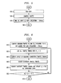
- Fig. 4 is a block diagram illustrating an exemplary process of a primary LSP generator 335 containing three connected modules for facilitating primary LSP configuration and trunk assignment. It should be appreciated that the three modules of Fig. 4, independently or corporately, receive and, if necessary, send information to and from the design inputs handler 310 and the network inputs handler 320 of Fig. 3. Similarly, the three modules can forward and receive information to and from the list generator 340 of Fig. 3.
- the primary LSPs are generated to reduce congestion within links under an element non-failure condition.
- the first module 410 provides a list of links whose utilization is above the targeted maximum utilization UN max , e.g., operating under a congestion status, for use in the successive module 420.
- the first module 410 provides this list to the second module 420 for further evaluation.
- An exemplary list of arbitrarily congested links, 12 and 7, with above target maximum utilizations is illustrated in Table 3. Link ID and % of UN max Link 12 - 120% Link 7-115%
- the second module 420 uses the above provided list of links under congestion, evaluates the list and provides a list of selected traffic trunks to which primary LSPs should be assigned. In this evaluation process, the second module 420 attempts to balance the total traffic volume to be routed through the primary LSPs while trying to minimize the maximum number of traffic trunks, with congested links, that should be routed through the primary LSPs.
- the second module 420 provides the list of identified traffic trunks to the third module 430 for further evaluation and assignment.
- An exemplary ordered list of arbitrary traffic trunks K-P contributing to the congestion of arbitrary links 12 and 7 is illustrated in Table 4. Link ID and % of UN max Contributing Trunks' Congestion (%) Link 12-120% Trunk K-75% Trunk L - 30% Trunk M - 15% Link 7-115% Trunk N - 90% Trunk O - 20% Trunk P - 5%
- the third module 430 assigns primary LSPs to each traffic trunk identified in the second module 420 while trying to minimize the maximum number of primary LSPs.
- the third module 430 implements an exemplary modified Djkstra algorithm to find LSPs with the largest residue capacities for each identified traffic trunk and outputs a list of primary LSPs for each traffic trunk, as well as the distributions of traffic over the primary paths.
- Fig. 5 is a flowchart outlining an exemplary congestion identifier process of the first module 410 of Fig. 4.
- the exemplary congestion identifier process provides a list of links whose utilization is above the design value UN max for evaluation by the second module 420 of Fig. 4.
- the exemplary congestion identifier process is outlined as follows: In step 510 a querying of link capacities is initiated by running OSPF for each traffic trunk under evaluation in the network 105.
- the OSPF model is run under a non-failure mode and determines the shortest link traversing paths between each traffic trunk under evaluation in the network 105.
- the process proceeds to step 520 where the total traffic load on each link is determined. In the above determination, consideration is not given to the bandwidth of each link.
- the process continues to step 530, where all links having a traffic load utilization above the targeted maximum utilization UN max are listed. For future reference, let L represent the total number of identified congested links.
- the process then ends in step 540, and the list of congested links is provided to the second module 420.
- the exemplary congestion identifier process of the first module 410 may be periodically initiated or aperiodically initiated by a fault/congestion status received by the traffic engineering system 100, or by other mechanisms as desired.
- OSPF Interior Gateway Protocols
- Fig. 6 is a flowchart outlining an exemplary contributing traffic trunk identifier process of the second module 420 of Fig. 4.
- One function of the contributing traffic trunk identifier process is to produce a list of traffic trunks to which primary LSPs should be assigned. A goal in producing this list is to identify a minimum number of traffic trunks that should be routed through primary LSPs while trying to minimize the total traffic volume to be routed through the primary LSPs. It is appreciated that, since a traffic trunk can traverse multiple links, when a primary LSP is assigned for a traffic trunk, congestion of multiple links traversed by a traffic truck can, accordingly, be alleviated.
- step 620 all traffic trunks containing traffic that traverses the identified congested links, having a positive V l , are identified.
- step 630 for each identified traffic trunk containing traffic that traverses the identified congested link, a computation is performed to determine the potential reduction of V l if the congested links are removed. However, reductions that result in a V l that are below zero are not considered.
- the contributions of each traffic trunk's traffic to the congestion in each given link are summed up and denoted as C k , where k represents the index of the trunk under evaluation.
- step 640 the traffic trunk with the largest value of C k is identified as an appropriate candidate traffic trunk for a primary LSP assignment. Where multiple such traffic trunks having the same value of C k are identified, the traffic trunk with the smallest traffic volume is selected as the appropriate candidate.
- step 650 the identified or selected traffic trunk contributing the most to link congestion (in step 640) is removed from the list of candidate traffic trunks and the V l for all remaining congested links are updated to reflect the "eliminated" traffic.
- step 660 if the remaining congested links and their associated congestion-contributing traffic trunks have a V l above zero, the process jumps to step 620 and steps 620-650 are repeated until all the respective V l 's are reduced to zero; otherwise the process goes to step 670 and ends.
- the process based on the above "best" removed congestion-contributing trunks, produces or prepares a list of candidate traffic trunks for LSP assignment by the third module 430.
- Fig. 7 is a flowchart outlining an exemplary primary LSP selector process of the third module 430 of Fig. 4.
- One function of the exemplary primary LSP path selector process is to assign primary LSPs to each trunk compiled in the candidate traffic trunk selector process of Fig. 6.
- An objective of the generator of primary LSPs is to minimize the maximum number of primary LSPs.
- the maximum number of primary LSPs for a traffic trunk should not be more than Max Prim , which is chosen as a design input provided in the design inputs handler 310, as discussed above.
- the primary LSP path selector process also outputs a list of primary LSPs and the corresponding assigned traffic trunks, as well as the corresponding traffic distribution profiles over the primary LSP paths.
- the exemplary primary LSP selector process compiles, using traffic trunks identified in the candidate traffic trunks outlined in the exemplary process of Fig. 6, a link-state database for the network 105, in terms of the additional traffic capacity each link can support without violating the maximum allowed utilization UN max .
- This additional traffic capacity can be referred to as the residual capacity of a respective link.
- the link-state database contains a list of directly connected links between every router and their residual capacities.
- step 710 the process evaluates the residual capacity of each link, starting from the largest traffic volume trunk in the traffic trunk identifier list, to be the smaller of either the value of the traffic volume or the value of the residue capacity of that link.
- step 720 a modified Djkstra algorithm is applied to each traffic trunk, as further discussed below, to find paths that constitute a LSP with the largest residue capacity for the traffic trunk.
- step 730 examines the current LSP with the largest residue capacity to see if the LSP's residue capacity is smaller than the volume of the traffic trunk being evaluated.
- step 750 the LSP is assigned with as much traffic volume up to the LSP's residue capacity. In this event, the process proceeds to step 750 where the link-state database is updated to reflect the above traffic trunk-to-LSP assignment. The process then reexamines the link-state database to find the next set of paths that constitute a LSP with the next largest residue capacity for the remaining unassigned traffic. If the next largest residue capacity LSP can handle the remaining traffic, then the LSP is assigned and, accordingly, the link-state database is similarly updated to reflect the new assignment. This process is repeated until all the remaining traffic can be assigned or, if the maximum number of LSPs ( Max prim ) has been reached, the process proceeds to step 740, as discussed below. If all the remaining traffic is assigned, then the process continues to step 770.
- step 740 either the remaining traffic is distributed among the existing LSP(s) so that the existing link capacity utilization of all existing LSPs' congestion profile is at the same level or the process uses OSPF routing, or any other appropriate routing scheme, for assigning the remaining traffic. In either event, after completion of step 740, the process continues to step 770.
- step 770 the link-state database list is tested to determine if all the trunks on the database list have been assigned. If all the trunks on the database list are not assigned, then the process jumps to step 710 and steps 710-770 are repeated until the above conditions are satisfied. Once all the traffic has been assigned, then the process proceeds to step 780 and is stopped.
- an exemplary modified Djkstra algorithm is applied to the parameters of the identified traffic trunks (to be removed) to find traffic trunks with the largest residue capacity and, correspondingly, to designate paths (LSP) suitable for rerouting the removed traffic trunks.
- LSP paths
- the modified Djkstra algorithm creates, for example, two sets of node sets: (1) PATH, where PATH is the set of nodes for which the best path from the computing ingress node has been found; and (2) TENT, where TENT is the set of nodes which are not in the set of PATH but are direct neighbors of nodes in PATH. Initially, these two sets can be empty sets.
- a vector (nodeID, a, b, c) can be used to represent a node in the node sets PATH and TENT, where the first argument, "nodeID”, is the node ID of the current node-
- the second argument, "a” is the maximum modified residual capacity from the computing ingress node to the current node.
- the third argument, "b” is the parent node that is in the PATH node set and directly connects to the current node.
- the last argument, "c" is the link between the parent node and the current node.
- the node set TENT is an ordered set in a descending order of the second argument, a.
- the exemplary process for creating the two sets of nodes, PATH and TENT, during the modified Djkstra algorithm is comprised of five steps, as discussed below:
- each link in the network is assigned a modified residual capacity by taking the minimum of the residual capacity of that link and the amount of traffic trunk to be routed.
- the process starts with the ingress node of the traffic trunk as the root tree for computing. This is accomplished by inserting a (myID, ⁇ , 0, 0) vector in PATH.
- step three for the node N, having a corresponding vector (N, a(N), b(N), c(N)), in PATH, find node N's neighbor, M, that is not in the node set PATH.
- M For each arbitrary link l, from N to M, define a vector (M, a(M),N, l ) where a(M) is equal to the minimum of the maximum modified residue capacity a(N) and the modified residue capacity of link l .
- step four the lead vector is removed from TENT. If the lead vector in TENT is the egress node of the traffic trunk, then it should be apparent that there are no other potentially bottlenecking links between the node N and the egressing node of the traffic trunk. Consequently, the algorithm continues onto step five to construct a LSP for the traffic trunk. Otherwise, the module updates PATH to include this TENT node and removes all vectors in TENT with the same node id as this TENT node, and then jumps back to step three, where steps three to four are repeated until the head vector in TENT becomes the egress node of the trunk.
- step five the algorithm constructs the primary LSP from the egress node of the traffic trunk to the ingress node based on the parent nodes and the connecting link arguments.
- the algorithm may then initiate construction of the primary LSPs using a configuration template generator 350 to facilitate command and control of the network resources to coordinate the primary LSP link, trunk, and network resource assignments. It should be apparent from the above discussion that multiple primary LSPs may be developed for traffic management.
- the exemplary modified Djkstra algorithm contains five distinct steps, it is apparent that one of ordinary skill may modify the exemplary modified Djkstra algorithm to provide additional or lesser steps in evaluating a LSP residue capacity without departing from the spirit and scope of this invention. Further, the exemplary modified Djkstra algorithm may construct the LSPs using more relaxed or more stringent, or other desired, conditions without departing from the spirit and scope of this invention. It should also be appreciated that the exemplary modified Djkstra algorithm may be readily implemented in software that can be used in a variety of hardware systems.
- Fig. 8 is a block diagram illustrating an exemplary alternate LSP generator 337.
- the exemplary alternate LSP generator 337 contains three connected modules for facilitating alternate LSP configuration and trunk assignment.
- the alternate LSPs operate to reroute network traffic in the event of a single network element failure or congestion event in the primary LSP.
- the methodology of alternate LSP generation can be summarized as follows: For each simulated single element failure anywhere in the network, a standard failure rerouting mechanism is initiated (e.g., OSPF). Links that become congested because of the rerouting are identified and alternate LSPs are generated to reroute the traffic trunks away from the congested links. This process is recursively applied one failure at a time to all network elements. It should be apparent that the alternate LSP is not applied to a congested link that is "outside" a primary LSP.
- OSPF standard failure rerouting mechanism
- the first module 810 of an exemplary alternate LSP generator 337 of Fig. 3 identifies congested links arising from a failure event rerouting and outputs a list of links whose utilization is above a targeted maximum utilization UF max .
- the second module 820 evaluates the congestion caused by the non-original traffic (traffic routed around the failed network element) and selects the minimum number of non-original traffic trunks that should be rerouted through alternate LSPs while at the same time trying to minimize the total non-original traffic volume to be rerouted through the alternate LSPs.
- the second module 820 generates a candidate trunk list similar in effect to the second module 420 of Fig. 4, but with some differences, as discussed below.
- the third module 830 assigns alternate LSPs to each traffic trunk selected from the trunk list provided in the above second module 820.
- the third module 830 attempts to minimize the number of alternate LSPs generated and generates the alternate LSP to trunk list.
- the alternate LSP provides protection to any single network element failure on its associated primary path. Hence, it is desirable that a primary LSP and its alternate LSP are disjointed to provide a reasonable degree of independence. If the primary LSP and alternate LSP are disjointed, then any single failure not along a primary path will not disconnect the primary path. However, it is possible that, in the design and implementation of alternate LSPs and primary LSPs, multiple alternate LSPs of the same primary LSP can have overlapping paths. Because a traffic trunk can traverse multiple links, congestion in a trunk can contribute to the congestion of more than one link at a time. It should be apparent, then, that when alternate LSPs are assigned for a traffic trunk, congestion on multiple links can ensuingly be mitigated.
- this second segment is referred to as a non-original traffic or, alternatively, non-original traffic trunks.
- Fig. 9 is a flowchart outlining an exemplary congestion identifier process of the first module 810 of Fig. 8.
- the congestion identifier process provides a list of identified links whose utilization is above a targeted maximum UFmax under a "considered" failure or congestion of a primary LSP.
- step 920 all traffic trunks routed by primary LSPs under non-failure conditions are examined to see if the primary LSPs are not affected by failure n. If no primary LSP traffic flows are affected, then the process continues to use the primary LSPs to route the traffic and the process proceeds to step 940. However, if any of the primary LSP are affected by the simulated single failure case n, then the process jumps to step 930 where OSPF is used to reroute the traffic trunks. For all other traffic trunks, OSPF for routing or rerouting may be used. In this event, the process proceeds to step 940.
- step 940 the process calculates the total gross traffic load on each link of the residual network without considering the bandwidth of the link.
- the process proceeds to step 950 where the process searches and finds all links whose traffic load utilization is above the targeted allowed maximum utilization UF max for a failure condition n.
- Step 950 compiles this list for use in the second module 820. For reference purposes, let L(n) denote the total number of congested links identified for a failure n.
- the process continues to step 960.
- step 960 the process tests the index of the single failure case n to see if n equals p, the maximum failure episode index. If n is not equal to p, then the process jumps to step 910, increments the failure case index by one, and repeats steps 910-960. Steps 910-960 are repeated until step 960 determines that n equals p; then the process continues on to step 970 and ends.
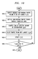
- Fig. 10 is a flowchart outlining an exemplary contributing traffic trunk identifier process of the second module 820.
- the exemplary contributing traffic trunk identifier process attempts to regulate the congestion caused by non-original traffic trunks. Specifically, the exemplary contributing traffic trunk identifier process attempts to minimize the number of non-original traffic trunks and the total non-original traffic trunk volume to be rerouted through alternate LSPs.
- V l (n) denote this number.
- the value V l (n) can be the sum of all the non-original traffic trunks if the utilization of original traffic trunks is already larger than UF max .
- step 1040 selects the traffic trunk with the largest C k (n) value among all k's and all n's as the candidate traffic trunk for alternate LSP assignment. If there are multiple such traffic trunks, the process selects the one with the smallest traffic volume of the entire set of evaluated traffic trunks.
- step 1050 the traffic trunk selected in step 1040 is removed in all the single failure cases.
- step 1060 the V l (n) values are tested to determine if they are all negligible or equal to zero. If all the V l (n)' s are not negligible or equal to zero, then the process jumps to step 1020 and steps 1020-1060 are repeated for the non-removed remaining traffic trunks until the V l (n) values are negligible or equal to zero. In this event, the process proceeds to step 1070 and ends.
- the exemplary alternate LSP selector process of the third module 830 assigns alternate LSPs to each traffic trunk selected from the results of the exemplary contributing traffic trunk identifier process of module 820.
- the exemplary alternate LSP selector process provides lists of alternate LSPs for each traffic trunk and distribution profiles of the traffic over the alternate paths. For example, with all identified traffic trunks removed for a single failure n, the process computes a link-state database for the network in terms of the additional traffic each link can support as constrained by a maximum allowed utilization UF max . This traffic is referred to as the residual capacity of a link for failure n. The process generates a link-state database containing a list of connected links to every router and their residual capacities for all single failure cases n.
- the alternate LSP selector process comprises at least three steps as follows:
- step one the process searches for alternate paths with residual capacities that are not in the primary LSP. This is accomplished by finding the traffic trunk with the largest traffic volume from the V(l) list identified in the second module 820.
- t be the traffic trunk with the largest traffic volume from the V(l) list and F be the set of all single failures in which the failure link is on the primary path of the traffic trunk t.
- T( t ) represent the traffic volume of traffic trunk t .
- MRes(k) min ⁇ T( t ), min ⁇ residue capacity of link k during failure n, n ⁇ F ⁇ .
- step two from application of the modified Djkstra algorithm, if the residual capacity of the identified LSP is smaller than the volume of the traffic trunk, the LSP's traffic volume is set to the LSP's residual capacity.
- the modified residual capacities of the link-state database is updated.
- the next largest residual capacity LSP is found based on the updated database. If all of the remaining traffic can be carried by the largest residual capacity LSP, then the residual capacities of the link-state database for all failure cases in the set F are updated and the next largest traffic trunk on the list is, in turn, evaluated.
- steps one and two are repeated until either all identified traffic trunks on the link-state database list have been assigned to alternate LSPs or the maximum number of alternate LSPs have been reached.
- the process may proceed to generate alternate LSP assignments via the template generator 370, which contains systems and methods to facilitate command and control of the network resources to coordinate the alternate ISP link, trunk, and network resource assignments.
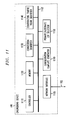
- Fig. 11 is a block diagram illustrating an exemplary network traffic engineering device 100.
- the exemplary traffic engineering device 100 may contain a controller 1110, a memory 1120, congestion identifier 1130, a contributing traffic trunk identifier 1140, a primary/alternate LSP selector 1150, a configuration template generator 1160, and a network interface 1105.
- the above components may be coupled together via a signal bus 1102.
- the controller 1110 operates to coordinate, individually or in the aggregate, other devices, shown or not shown, connected to the bus 1102.
- the bus 1102 may be any form of a communication bus, wired or wireless.
- the exemplary traffic engineering device 100 may be implemented by one or more general or special purpose computers, programmed microprocessors or micro-controllers and peripheral integrated circuit elements, ASICS or other logic circuits such as discrete element circuits, programmable logic devices such as PLD, PLA, FPGA or the like.
- ASICS or other logic circuits such as discrete element circuits, programmable logic devices such as PLD, PLA, FPGA or the like.
- any finite state machine that is capable of implementing the processes of Figs. 2-10 can be used to implement the exemplary traffic engineering device 100 according to this invention.
- Fig. 11 illustrates a bus architecture, any architecture may be used as is well known to one of ordinary skill.
- each of the devices in the exemplary traffic engineering device 100 may contain its own individual memory or controller.
- the congestion identifier 1130 via information provided by the controller 1110 and memory 1120, outputs a list of links whose utilization is above a targeted maximum utilization UN max .
- the contributing traffic trunk identifier 1140 outputs a list of traffic trunks to which primary LSPs should be assigned.
- the primary/alternate LSP selector 1150 evaluates the identified traffic trunks and assigns selected traffic trunks to primary/alternate LSPs.
- the configuration template generator 1160 generates command and control signals through the network interface 1105 to build or prepare for building the appropriate connections for facilitating rerouting of the network's paths in accordance with the primary/alternate assignments.
- the network interface 1105 acts as an input/output interface between the exemplary traffic engineering device 100 and the network 105. Communication between the network 105 and the exemplary traffic engineering device 100 is provided through a communications/data bus 102.
- FIG. 11 illustrates various distinct and separate elements of the exemplary traffic engineering device 100, it is apparent that one of ordinary skill may suitably combine or further distinguish the various elements of exemplary traffic engineering device 100 without departing from the spirit and scope of the invention.
- IP Internet protocol
- providers of Internet services will be able to apply the capabilities of Multiprotocol Label Switching technology for traffic engineering and failure protection/restoration of an IP network.
- the invention can be used with many other types of communication systems, including wired and wireless communication systems, computer, cable, satellite, corporate or other similar networks that deal with traffic engineering concerns.
- routing methods other than OSPF may be used in determining the traffic profiles, such as IS-IS or IGP, etc. Accordingly, preferred embodiments of the invention as set forth herein are intended to be illustrative, not limiting. Various changes may be made without departing from the spirit and scope of the invention.
Landscapes
- Engineering & Computer Science (AREA)
- Computer Networks & Wireless Communication (AREA)
- Signal Processing (AREA)
- Data Exchanges In Wide-Area Networks (AREA)
- Telephonic Communication Services (AREA)
- Monitoring And Testing Of Exchanges (AREA)
Abstract
Description
| Traffic Trunks | Paths from Originating Router A | Paths from Originating Router B | Paths from Originating Router C |
| BA | 1-2-3 | 3-2-1 | |
| C | 7 | 7 | |
| AC | 4-5-6 | 6-5-4 |
| Primary LSP(s) | Alternate LSP(s) | ||
| Egressing Router | Paths from | Paths from Originating | |
| Originating | Router A | ||
| Router A | |||
| C | 1-11-14-6 | - | 4-12-2-8 |
| Link ID and % of UNmax |
| Link 12 - 120% |
| Link 7-115% |
| Link ID and % of UNmax | Contributing Trunks' Congestion (%) |
| Link 12-120% | Trunk K-75% |
| Trunk L - 30% | |
| Trunk M - 15% | |
| Link 7-115% | Trunk N - 90% |
| Trunk O - 20% | |
| Trunk P - 5% |
Claims (12)
- A method for routing traffic in a network comprised of a plurality of links to selectively off-load traffic from congested portions of the network to portions that are less congested, comprising:identifying which of said links are congested and which of said links are not congested;identifying traffic trunks that contribute to traffic of the identified congested network links;selecting rerouting traffic trunks where each of the rerouting traffic trunks are traffic trunks that contribute to the traffic of the identified congested network links;ordering the rerouting traffic trunks in congestion contribution order; andrerouting portions of the traffic in the rerouting traffic trunks that contribute to the identified congested network links, based on a predetermined parameter, using a second routing technique to reduce the congestion of the network.
- The method of claim 1, wherein the predetermined parameter is a traffic load parameter, the selecting rerouting traffic trunks comprising:generating a minimum traffic off-load volume V l , for each of the identified congested network links I = 1, 2, 3, .. L, where L is the total number of congested network links, that brings a traffic load of network link l to below the traffic load parameter.
- The method of claim 2, wherein the selected rerouting traffic trunk is selected from the identified traffic trunks, starting with a traffic trunk having a greatest volume of traffic contribution to the traffic of the corresponding congested network link.
- The method of claim 2, further comprising:a) generating a residue capacity for all the network links of the network after the traffic contribution of the selected rerouting traffic trunk is removed from the corresponding congested network link;b) generating a modified residue capacity for all the network links based on the residue capacity and traffic contribution of the selected rerouting traffic trunk; andc) generating a label switching path (LSP) having an LSP residue capacity for the traffic portion of the selected rerouting traffic trunk.
- The method of claim 4, further comprising:d) adding the LSP of step c to route the traffic portion of the selected rerouting traffic trunk;e) adding the LSP residue capacity as added traffic to the network;f) generating a new residue capacity for all the network links based on the residue capacity and the added traffic;g) generating another LSP having another LSP residue capacity for another traffic portion of the selected rerouting traffic trunk if the LSP residue capacity is less than the traffic portion of the selected rerouting traffic trunk.h) repeating steps d-g until either new traffic of the identified congested traffic link is approximately less than or equal to the predetermined parameter, or until a predetermined maximum number of LSPs has been reached.i) selecting a next traffic trunk from the list and removing a traffic portion contribution of the next traffic trunk that contributes to the corresponding identified congested network link from the network, if the maximum number of LSPs has not been reached; andj) repeating steps a-i until all traffic of the rerouting traffic trunks have been routed with LSPs or until the maximum number of LPSs has been reached.
- The method as in claim 5, wherein the LSPs are selected in greatest residue capacity order, the method further comprising:k) generating a Path node list and a Tent node list for building a path from an ingress node of the selected rerouting traffic trunk to an egressing node of the selected rerouting traffic trunk, wherein the Path comprises:l) starting a first node set path from the ingress node of the selected ingressing rerouting traffic trunk;m) finding all nearest neighbor nodes not in the first node set;n) placing all nearest node neighbors in a second node set ordered based on their maximum modified residue capacity;o) removing a lead node in the second node set;p) updating the first node set with the lead node if the lead node is not an egressing node and deleting all nodes with a same node id as the lead node from the second node set;q) repeating steps m-p until the lead node is an egressing node; andr) constructing a best path primary LSP from the nodes listed in the first node set.
- A multi-protocol label switching (MPLS) device in a network comprising:a congestion identifying device, wherein the congestion identifying device identifies, based on a predetermined traffic load parameter, a congestion of network links;a contributing traffic trunk identifying device, wherein the contributing traffic trunk identifying device identifies traffic trunks that contribute to the congestion of the congested network links; anda LSP selector device, wherein the LSP selector device selects rerouting LSP traffic paths for the identified traffic trunks to reduce the traffic of the congested network links.
- The device according to claim 7, wherein the contributing traffic trunk identifying device:generates a minimum traffic off-load volume Vl , for each of the congested network links l=1, 2,..L, where L is the total number of congested network links, that brings a traffic load of a network link l to below the traffic load parameter;generates a list of traffic trunks corresponding to each of the identified congested network links where each of the traffic trunks in the list contributes to traffic of a corresponding identified congested network link;selects a traffic trunk from the list based on contribution of the selected traffic trunk to the traffic of the corresponding congested network link as a rerouting traffic trunk; andremoves a traffic portion of the selected rerouting traffic trunk that contributes to the corresponding identified congested network link from the network.
- The device of claim 8, wherein the contributing traffic trunk identifying device selects a rerouting traffic trunk from the list of traffic trunks, starting with a traffic trunk having a greatest volume of traffic contribution to the traffic of the corresponding congested network link.
- The device of claim 9, wherein the LSP selector device:a) generates a residue capacity for all the network links of the network after the traffic contribution of the selected rerouting traffic trunk is removed from the corresponding congested network link;b) generates a modified residue capacity for all the network links based on the residue capacity and traffic contribution of the selected rerouting traffic trunk; andc) generates a label switching path (LSP) having an LSP residue capacity for the traffic portion of the selected rerouting traffic trunk,
- The device of claim 10, wherein the LSP selector device:d). adds the LSP of step c to route the traffic portion of the selected rerouting traffic trunk;e) adds the LSP residue capacity as added traffic to the network;f) generates a new residue capacity for all the network links based on the residue capacity and the added traffic;g) generates another LSP having another LSP residue capacity for another traffic portion of the selected rerouting traffic trunk if the LSP residue capacity is less than the traffic portion of the selected rerouting traffic trunk;h) repeats steps d-g until either new traffic of the identified congested traffic link is approximately less than or equal to the predetermined parameter, or until a predetermined maximum number of LSPs has been reached,i) selects a next traffic trunk from the list and removes a traffic portion contribution of the next traffic trunk that contributes to the corresponding identified congested network link from the network, if the maximum number of LSPs has not been reached; andj) repeats steps a-i until all traffic of the rerouting traffic trunks have been routed with LSPs or until the maximum number of LSPs has been reached.
- The device as in claim 11, wherein the LSP selector device selects LSPs in greatest residue capacity order, wherein the LSP selector:k) generates a PATH node list and a TENT node list for building a path from an ingress node of the selected rerouting traffic trunk to an egressing node of the selected rerouting traffic trunk;l) starts a first node set path from the ingress node of the selected ingressing rerouting traffic trunk;m) finds all nearest neighbor nodes not in the first node set;n) places all nearest node neighbors in a second node set ordered based on their maximum modified residue capacity;o) removes a lead node in the second node set;p) updates the first node set with the lead node if the lead node is not an egressing node and deletes all nodes with a same node id as the lead node from the second node set;q) repeats steps m-p until the lead node is an egressing node; andr) constructs a best path primary LSP from the nodes listed in the first node set.
Priority Applications (1)
| Application Number | Priority Date | Filing Date | Title |
|---|---|---|---|
| EP10181152A EP2259503A3 (en) | 2001-03-28 | 2002-03-27 | Method and apparatus for communications traffic engineering |
Applications Claiming Priority (2)
| Application Number | Priority Date | Filing Date | Title |
|---|---|---|---|
| US819555 | 2001-03-28 | ||
| US09/819,555 US7230924B2 (en) | 2001-03-28 | 2001-03-28 | Method and apparatus for communications traffic engineering |
Related Child Applications (1)
| Application Number | Title | Priority Date | Filing Date |
|---|---|---|---|
| EP10181152.9 Division-Into | 2010-09-28 |
Publications (3)
| Publication Number | Publication Date |
|---|---|
| EP1246415A2 true EP1246415A2 (en) | 2002-10-02 |
| EP1246415A3 EP1246415A3 (en) | 2005-09-07 |
| EP1246415B1 EP1246415B1 (en) | 2010-12-15 |
Family
ID=25228462
Family Applications (2)
| Application Number | Title | Priority Date | Filing Date |
|---|---|---|---|
| EP10181152A Withdrawn EP2259503A3 (en) | 2001-03-28 | 2002-03-27 | Method and apparatus for communications traffic engineering |
| EP02252264A Expired - Lifetime EP1246415B1 (en) | 2001-03-28 | 2002-03-27 | Method and apparatus for communications traffic engineering |
Family Applications Before (1)
| Application Number | Title | Priority Date | Filing Date |
|---|---|---|---|
| EP10181152A Withdrawn EP2259503A3 (en) | 2001-03-28 | 2002-03-27 | Method and apparatus for communications traffic engineering |
Country Status (4)
| Country | Link |
|---|---|
| US (3) | US7230924B2 (en) |
| EP (2) | EP2259503A3 (en) |
| CA (1) | CA2379043C (en) |
| DE (1) | DE60238577D1 (en) |
Cited By (8)
| Publication number | Priority date | Publication date | Assignee | Title |
|---|---|---|---|---|
| WO2003045016A1 (en) * | 2001-11-16 | 2003-05-30 | Telstra New Wave Pty Ltd | Active networks |
| US6714787B2 (en) * | 2002-01-17 | 2004-03-30 | Motorola, Inc. | Method and apparatus for adapting a routing map for a wireless communications network |
| EP1560375A1 (en) * | 2004-01-30 | 2005-08-03 | Hitachi, Ltd. | Rate adaptation methods and devices in presence of network congestion. |
| GB2412033A (en) * | 2004-02-12 | 2005-09-14 | Parc Technologies Ltd | Traffic flow determination in communications networks |
| GB2420675A (en) * | 2004-11-30 | 2006-05-31 | Hewlett Packard Development Co | Multi protocol Label switching (MPLS) path fault management |
| EP2291956B1 (en) * | 2008-04-28 | 2014-03-05 | Tdf | Method of managing a transmission network of mpls type |
| WO2015156925A3 (en) * | 2014-04-10 | 2016-01-21 | Qualcomm Incorporated | Congestion control scheme |
| CN119155248A (en) * | 2024-11-13 | 2024-12-17 | 湖南国科超算科技有限公司 | Centralized control RoCEv network congestion control method |
Families Citing this family (69)
| Publication number | Priority date | Publication date | Assignee | Title |
|---|---|---|---|---|
| US7126907B2 (en) * | 2001-08-31 | 2006-10-24 | Tropic Networks Inc. | Label switched communication network, a method of conditioning the network and a method of data transmission |
| US7830787B1 (en) * | 2001-09-25 | 2010-11-09 | Cisco Technology, Inc. | Flooding control for multicast distribution tunnel |
| US20030063613A1 (en) * | 2001-09-28 | 2003-04-03 | Carpini Walter Joseph | Label switched communication network and system and method for path restoration |
| WO2003029986A1 (en) * | 2001-10-04 | 2003-04-10 | Tejas Networks India Pvt. Ltd. | Method for designing low cost static networks |
| US7535929B2 (en) * | 2001-10-25 | 2009-05-19 | Sandeep Singhai | System and method for token-based PPP fragment scheduling |
| US7743139B1 (en) * | 2001-10-30 | 2010-06-22 | At&T Intellectual Property Ii, L.P. | Method of provisioning a packet network for handling incoming traffic demands |
| US20030145105A1 (en) * | 2002-01-30 | 2003-07-31 | Harikishan Desineni | Method and apparatus for obtaining information about one or more paths terminating at a subject node for a group of packets |
| US7027396B1 (en) * | 2002-02-13 | 2006-04-11 | At&T Corp. | Traffic matrix computation for a backbone network supporting virtual private networks |
| FR2848757B1 (en) * | 2002-12-17 | 2005-03-11 | Cit Alcatel | DEVICE FOR DETERMINING COMMUNICATION PATHS IN A LABEL-SWITCHING COMMUNICATIONS NETWORK, IN THE PRESENCE OF SELECTION ATTRIBUTES |
| US7872976B2 (en) * | 2003-05-02 | 2011-01-18 | Alcatel-Lucent Usa Inc. | System and method for multi-protocol label switching network tuning |
| DE10341337A1 (en) * | 2003-09-08 | 2005-03-10 | Siemens Ag | Configuration of a computer network comprising a number of computers by considering the network design using both a routing protocol and a path definition protocol |
| US7580905B2 (en) * | 2003-12-15 | 2009-08-25 | Intel Corporation | Adaptive configuration of platform |
| US7487258B2 (en) * | 2004-01-30 | 2009-02-03 | International Business Machines Corporation | Arbitration in a computing utility system |
| US7706411B2 (en) * | 2004-03-29 | 2010-04-27 | Hewlett-Packard Development Company, L.P. | Handling oversubscribed mesh ports with re-tagging |
| US7031262B2 (en) * | 2004-05-19 | 2006-04-18 | Cisco Technology, Inc. | Reoptimization triggering by path computation elements |
| US20060005232A1 (en) * | 2004-06-30 | 2006-01-05 | Wilson Richard A Jr | Path utilization device discovery |
| JP4379237B2 (en) * | 2004-07-14 | 2009-12-09 | ソニー株式会社 | Wireless communication system, wireless communication apparatus, wireless communication method, and computer program |
| US8180883B1 (en) * | 2004-08-02 | 2012-05-15 | Cisco Technology, Inc. | Method and system for processing directives included in management events |
| US7965626B2 (en) * | 2004-08-03 | 2011-06-21 | Hewlett-Packard Development Company, L.P. | System and method for transferring data on a data network using multiple paths |
| US8045453B2 (en) * | 2005-01-20 | 2011-10-25 | Alcatel Lucent | Methods and systems for alleviating congestion in a connection-oriented data network |
| US8089964B2 (en) | 2005-04-05 | 2012-01-03 | Cisco Technology, Inc. | Transporting multicast over MPLS backbone using virtual interfaces to perform reverse-path forwarding checks |
| DE102005017021A1 (en) * | 2005-04-13 | 2006-10-19 | Siemens Ag | Method and device for communication between network node elements |
| JP4441931B2 (en) * | 2005-05-06 | 2010-03-31 | 村田機械株式会社 | Conveyor cart system |
| US7580359B2 (en) * | 2006-02-14 | 2009-08-25 | Alcatel Lucent | Method and system for maximizing network capacity utilization in multiprotocol label switched networks by moving label switched paths |
| US8934486B2 (en) * | 2006-03-16 | 2015-01-13 | Cisco Technology, Inc. | System and method for implementing multicast over a label-switched core network |
| US20080081339A1 (en) * | 2006-10-03 | 2008-04-03 | The Brigham And Women's Hospital, Inc. | Tumor associated markers in the diagnosis of prostate cancer |
| US7742409B2 (en) * | 2007-08-15 | 2010-06-22 | At&T Intellectual Property Ii, L.P. | Method and apparatus for compensating for performance degradation of an application session |
| US7809970B2 (en) * | 2007-08-27 | 2010-10-05 | International Business Machines Corporation | System and method for providing a high-speed message passing interface for barrier operations in a multi-tiered full-graph interconnect architecture |
| US7769891B2 (en) * | 2007-08-27 | 2010-08-03 | International Business Machines Corporation | System and method for providing multiple redundant direct routes between supernodes of a multi-tiered full-graph interconnect architecture |
| US8185896B2 (en) | 2007-08-27 | 2012-05-22 | International Business Machines Corporation | Method for data processing using a multi-tiered full-graph interconnect architecture |
| US7958183B2 (en) | 2007-08-27 | 2011-06-07 | International Business Machines Corporation | Performing collective operations using software setup and partial software execution at leaf nodes in a multi-tiered full-graph interconnect architecture |
| US7958182B2 (en) | 2007-08-27 | 2011-06-07 | International Business Machines Corporation | Providing full hardware support of collective operations in a multi-tiered full-graph interconnect architecture |
| US8140731B2 (en) | 2007-08-27 | 2012-03-20 | International Business Machines Corporation | System for data processing using a multi-tiered full-graph interconnect architecture |
| US7840703B2 (en) * | 2007-08-27 | 2010-11-23 | International Business Machines Corporation | System and method for dynamically supporting indirect routing within a multi-tiered full-graph interconnect architecture |
| US7822889B2 (en) * | 2007-08-27 | 2010-10-26 | International Business Machines Corporation | Direct/indirect transmission of information using a multi-tiered full-graph interconnect architecture |
| US8014387B2 (en) * | 2007-08-27 | 2011-09-06 | International Business Machines Corporation | Providing a fully non-blocking switch in a supernode of a multi-tiered full-graph interconnect architecture |
| US7904590B2 (en) | 2007-08-27 | 2011-03-08 | International Business Machines Corporation | Routing information through a data processing system implementing a multi-tiered full-graph interconnect architecture |
| US7793158B2 (en) * | 2007-08-27 | 2010-09-07 | International Business Machines Corporation | Providing reliability of communication between supernodes of a multi-tiered full-graph interconnect architecture |
| US8108545B2 (en) | 2007-08-27 | 2012-01-31 | International Business Machines Corporation | Packet coalescing in virtual channels of a data processing system in a multi-tiered full-graph interconnect architecture |
| US7769892B2 (en) | 2007-08-27 | 2010-08-03 | International Business Machines Corporation | System and method for handling indirect routing of information between supernodes of a multi-tiered full-graph interconnect architecture |
| US7827428B2 (en) | 2007-08-31 | 2010-11-02 | International Business Machines Corporation | System for providing a cluster-wide system clock in a multi-tiered full-graph interconnect architecture |
| US7921316B2 (en) | 2007-09-11 | 2011-04-05 | International Business Machines Corporation | Cluster-wide system clock in a multi-tiered full-graph interconnect architecture |
| US7940753B2 (en) * | 2007-11-29 | 2011-05-10 | Alcatel Lucent | Enhancing routing optimality in IP networks requiring path establishment |
| US7916657B2 (en) * | 2008-01-22 | 2011-03-29 | At&T Intellectual Property Ii, L.P. | Network performance and reliability evaluation taking into account abstract components |
| US7779148B2 (en) | 2008-02-01 | 2010-08-17 | International Business Machines Corporation | Dynamic routing based on information of not responded active source requests quantity received in broadcast heartbeat signal and stored in local data structure for other processor chips |
| US20090198956A1 (en) * | 2008-02-01 | 2009-08-06 | Arimilli Lakshminarayana B | System and Method for Data Processing Using a Low-Cost Two-Tier Full-Graph Interconnect Architecture |
| US8077602B2 (en) * | 2008-02-01 | 2011-12-13 | International Business Machines Corporation | Performing dynamic request routing based on broadcast queue depths |
| US7684316B2 (en) * | 2008-02-12 | 2010-03-23 | Cisco Technology, Inc. | Multicast fast reroute for network topologies |
| US8335154B2 (en) * | 2008-07-30 | 2012-12-18 | Verizon Patent And Licensing Inc. | Method and system for providing fault detection and notification for composite transport groups |
| JP5593335B2 (en) * | 2009-02-26 | 2014-09-24 | コーニンクレッカ フィリップス エヌ ヴェ | Routing messages across a network of interconnected devices in a networked control system |
| US8565247B2 (en) | 2009-08-19 | 2013-10-22 | Brocade Communications Systems, Inc. | Techniques for efficiently updating routing information upon shortest path tree computation |
| US8873563B2 (en) * | 2009-09-21 | 2014-10-28 | Brocade Communications Systems, Inc. | Techniques for next-hop optimization |
| US8417778B2 (en) * | 2009-12-17 | 2013-04-09 | International Business Machines Corporation | Collective acceleration unit tree flow control and retransmit |
| JP5173084B2 (en) * | 2010-04-09 | 2013-03-27 | エヌイーシー ヨーロッパ リミテッド | Routing for energy efficiency |
| US8503464B2 (en) | 2011-05-20 | 2013-08-06 | Brocade Communications Systems, Inc. | Techniques for efficiently updating routing information |
| EP2721426A4 (en) * | 2011-06-16 | 2015-04-01 | Nokia Solutions & Networks Oy | Dynamic traffic offloading |
| US9780964B1 (en) | 2012-01-23 | 2017-10-03 | Cisco Technology, Inc. | System and method for ring protection switching over adaptive modulation microwave links |
| US9285865B2 (en) | 2012-06-29 | 2016-03-15 | Oracle International Corporation | Dynamic link scaling based on bandwidth utilization |
| US20140040526A1 (en) * | 2012-07-31 | 2014-02-06 | Bruce J. Chang | Coherent data forwarding when link congestion occurs in a multi-node coherent system |
| US9161259B2 (en) * | 2013-03-20 | 2015-10-13 | Cisco Technology, Inc. | System and method for layer 3 ring protection with adaptive bandwidth microwave links in a network environment |
| US9392526B2 (en) | 2013-05-28 | 2016-07-12 | Cisco Technology, Inc. | Protection against fading in a network ring |
| US9407561B2 (en) | 2013-06-19 | 2016-08-02 | Huawei Technologies Co., Ld. | Systems and methods for traffic engineering in software defined networks |
| US9929939B2 (en) | 2013-12-26 | 2018-03-27 | Coriant Operations, Inc. | Systems, apparatuses, and methods for rerouting network traffic |
| US9369338B1 (en) | 2013-12-30 | 2016-06-14 | Google Inc. | Network link capacity determination |
| US10129158B2 (en) * | 2015-04-17 | 2018-11-13 | Parallel Wireless, Inc. | MaxMesh: mesh backhaul routing |
| US10462036B2 (en) * | 2016-08-24 | 2019-10-29 | Google Llc | Line rate ethernet traffic testing |
| US11323374B2 (en) | 2019-09-25 | 2022-05-03 | Juniper Networks, Inc. | Visualizing network traffic plans based on egress peer engineering |
| US11838210B2 (en) | 2021-03-31 | 2023-12-05 | Cisco Technology, Inc. | Local congestion mitigation |
| CN119892756B (en) * | 2025-01-02 | 2025-10-21 | 烽火通信科技股份有限公司 | A method, system, device and medium for clearing residual SPC services in an ASON network |
Family Cites Families (28)
| Publication number | Priority date | Publication date | Assignee | Title |
|---|---|---|---|---|
| US5253248A (en) * | 1990-07-03 | 1993-10-12 | At&T Bell Laboratories | Congestion control for connectionless traffic in data networks via alternate routing |
| US5164938A (en) * | 1991-03-28 | 1992-11-17 | Sprint International Communications Corp. | Bandwidth seizing in integrated services networks |
| US5533198A (en) * | 1992-11-30 | 1996-07-02 | Cray Research, Inc. | Direction order priority routing of packets between nodes in a networked system |
| EP0701349A1 (en) * | 1994-09-07 | 1996-03-13 | T.R.T. Telecommunications Radioelectriques Et Telephoniques | Data transmission system and node with congestion monitoring |
| US5854899A (en) | 1996-05-09 | 1998-12-29 | Bay Networks, Inc. | Method and apparatus for managing virtual circuits and routing packets in a network/subnetwork environment |
| US5872773A (en) | 1996-05-17 | 1999-02-16 | Lucent Technologies Inc. | Virtual trees routing protocol for an ATM-based mobile network |
| JP2964957B2 (en) * | 1996-08-15 | 1999-10-18 | 日本電気株式会社 | High-speed routing control method |
| GB9625020D0 (en) * | 1996-11-29 | 1997-01-15 | Northern Telecom Ltd | Network restoration |
| US6195354B1 (en) * | 1997-07-16 | 2001-02-27 | Nortel Networks Limited | Route selection for path balancing in connection-oriented packet switching networks |
| US6256295B1 (en) * | 1997-09-25 | 2001-07-03 | Nortel Networks Limited | Method and apparatus for determining multiple minimally-overlapping paths between nodes in a network |
| US6606297B1 (en) * | 1998-05-29 | 2003-08-12 | Tellabs Operations, Inc. | Bi-directional ring network having minimum spare bandwidth allocation and corresponding connection admission control |
| JP3072728B2 (en) * | 1998-07-16 | 2000-08-07 | 日本電気株式会社 | Multipoint connection failure recovery method and system |
| FR2782218B1 (en) * | 1998-08-06 | 2002-05-17 | Alsthom Cge Alkatel | ROUTING CALLS WITH OVERFLOWS IN A PRIVATE NETWORK |
| US6795399B1 (en) * | 1998-11-24 | 2004-09-21 | Lucent Technologies Inc. | Link capacity computation methods and apparatus for designing IP networks with performance guarantees |
| US6493317B1 (en) * | 1998-12-18 | 2002-12-10 | Cisco Technology, Inc. | Traffic engineering technique for routing inter-class traffic in a computer network |
| US7012892B1 (en) * | 1999-04-16 | 2006-03-14 | Alcatel Canada Inc. | Method and apparatus for supporting connection type partitioning in a communications network |
| AU7078500A (en) | 1999-09-14 | 2001-04-17 | Megaxess, Inc. | Method and apparatus for prevention of congestion in atm networks through atm protection switching |
| US6665273B1 (en) * | 2000-01-11 | 2003-12-16 | Cisco Technology, Inc. | Dynamically adjusting multiprotocol label switching (MPLS) traffic engineering tunnel bandwidth |
| JP4150159B2 (en) * | 2000-03-01 | 2008-09-17 | 富士通株式会社 | Transmission path control device, transmission path control method, and medium recording transmission path control program |
| US6574195B2 (en) * | 2000-04-19 | 2003-06-03 | Caspian Networks, Inc. | Micro-flow management |
| US6766373B1 (en) * | 2000-05-31 | 2004-07-20 | International Business Machines Corporation | Dynamic, seamless switching of a network session from one connection route to another |
| US6778496B1 (en) * | 2000-06-07 | 2004-08-17 | Lucent Technologies Inc. | Distributed call admission and load balancing method and apparatus for packet networks |
| US6768718B1 (en) * | 2000-08-01 | 2004-07-27 | Nortel Networks Limited | Courteous routing |
| US7177927B1 (en) * | 2000-08-22 | 2007-02-13 | At&T Corp. | Method for monitoring a network |
| US7127056B2 (en) * | 2000-12-26 | 2006-10-24 | Nortel Networks Limited | Dynamic adaptation to congestion in connection-oriented networks |
| US7065045B2 (en) * | 2001-01-03 | 2006-06-20 | International Business Machines Corporation | Method and system for providing an optimal path choice for differentiated services |
| US6956821B2 (en) * | 2001-01-30 | 2005-10-18 | Telefonaktiebolaget L M Ericsson (Publ) | Path determination in a data network |
| US7609623B2 (en) * | 2003-12-23 | 2009-10-27 | At&T Intellectual Property I, L.P. | Method and system for automatically rerouting data from an overbalanced logical circuit in a data network |
-
2001
- 2001-03-28 US US09/819,555 patent/US7230924B2/en not_active Expired - Fee Related
-
2002
- 2002-03-26 CA CA002379043A patent/CA2379043C/en not_active Expired - Fee Related
- 2002-03-27 EP EP10181152A patent/EP2259503A3/en not_active Withdrawn
- 2002-03-27 DE DE60238577T patent/DE60238577D1/en not_active Expired - Lifetime
- 2002-03-27 EP EP02252264A patent/EP1246415B1/en not_active Expired - Lifetime
-
2005
- 2005-08-26 US US11/212,945 patent/US7778182B2/en not_active Expired - Fee Related
-
2009
- 2009-12-11 US US12/635,905 patent/US7948899B2/en not_active Expired - Fee Related
Cited By (16)
| Publication number | Priority date | Publication date | Assignee | Title |
|---|---|---|---|---|
| US8116325B2 (en) | 2001-11-16 | 2012-02-14 | Telstra Corporation Limited | Active networks |
| WO2003045016A1 (en) * | 2001-11-16 | 2003-05-30 | Telstra New Wave Pty Ltd | Active networks |
| US6714787B2 (en) * | 2002-01-17 | 2004-03-30 | Motorola, Inc. | Method and apparatus for adapting a routing map for a wireless communications network |
| EP1560375A1 (en) * | 2004-01-30 | 2005-08-03 | Hitachi, Ltd. | Rate adaptation methods and devices in presence of network congestion. |
| US7380019B2 (en) | 2004-01-30 | 2008-05-27 | Hitachi, Ltd. | Path control method |
| US7421511B2 (en) | 2004-01-30 | 2008-09-02 | Hitachi, Ltd. | Path control method |
| GB2412033A (en) * | 2004-02-12 | 2005-09-14 | Parc Technologies Ltd | Traffic flow determination in communications networks |
| US8194546B2 (en) | 2004-02-12 | 2012-06-05 | Cisco Technology, Inc. | Traffic flow determination in communications networks |
| GB2412033B (en) * | 2004-02-12 | 2006-11-15 | Parc Technologies Ltd | Traffic flow determination in communications networks |
| GB2420675B (en) * | 2004-11-30 | 2009-06-24 | Hewlett Packard Development Co | MPLS VPN fault management using IGP monitoring system |
| GB2420675A (en) * | 2004-11-30 | 2006-05-31 | Hewlett Packard Development Co | Multi protocol Label switching (MPLS) path fault management |
| US8572234B2 (en) | 2004-11-30 | 2013-10-29 | Hewlett-Packard Development, L.P. | MPLS VPN fault management using IGP monitoring system |
| EP2291956B1 (en) * | 2008-04-28 | 2014-03-05 | Tdf | Method of managing a transmission network of mpls type |
| WO2015156925A3 (en) * | 2014-04-10 | 2016-01-21 | Qualcomm Incorporated | Congestion control scheme |
| US9591509B2 (en) | 2014-04-10 | 2017-03-07 | Qualcomm Incorporated | Congestion control scheme |
| CN119155248A (en) * | 2024-11-13 | 2024-12-17 | 湖南国科超算科技有限公司 | Centralized control RoCEv network congestion control method |
Also Published As
| Publication number | Publication date |
|---|---|
| EP1246415B1 (en) | 2010-12-15 |
| EP2259503A3 (en) | 2011-03-09 |
| CA2379043A1 (en) | 2002-09-28 |
| CA2379043C (en) | 2007-01-09 |
| US20020186658A1 (en) | 2002-12-12 |
| DE60238577D1 (en) | 2011-01-27 |
| US7230924B2 (en) | 2007-06-12 |
| US7948899B2 (en) | 2011-05-24 |
| EP2259503A2 (en) | 2010-12-08 |
| EP1246415A3 (en) | 2005-09-07 |
| US20100091656A1 (en) | 2010-04-15 |
| US20060018256A1 (en) | 2006-01-26 |
| US7778182B2 (en) | 2010-08-17 |
Similar Documents
| Publication | Publication Date | Title |
|---|---|---|
| US7230924B2 (en) | Method and apparatus for communications traffic engineering | |
| JP4828865B2 (en) | Efficient and robust routing independent of traffic pattern variability | |
| US8194546B2 (en) | Traffic flow determination in communications networks | |
| US8463916B2 (en) | Traffic engineering and bandwidth management of bundled links | |
| US6978394B1 (en) | Linear program-based technique for placing FRR TE tunnels with bandwidth guarantee | |
| EP1443722B1 (en) | Transmission bandwidth control device | |
| US8477769B2 (en) | Flexible shared mesh protection services for intelligent TDM-based optical transport networks | |
| US20150326426A1 (en) | Partial software defined network switch replacement in ip networks | |
| CN112532518B (en) | Path selection method and device of segment routing strategy | |
| Tomovic et al. | Performance comparison of QoS routing algorithms applicable to large-scale SDN networks | |
| Nucci et al. | IGP link weight assignment for operational tier-1 backbones | |
| EP1776813A2 (en) | Method for forwarding traffic having a predetermined category of transmission service in a connectionless communications network | |
| US7443832B2 (en) | Device for determining switching paths in a label switched communication network in the presence of selection attributes | |
| US20040233850A1 (en) | Device and a method for determining routing paths in a communication network in the presence of selection attributes | |
| Bhatia et al. | Bandwidth guaranteed routing with fast restoration against link and node failures | |
| US20050174934A1 (en) | Traffic-independent allocation of working and restoration capacity in networks | |
| JP4603519B2 (en) | Route calculation method, route calculation program, route calculation device, and node | |
| Mélon et al. | Decentralized local backup LSP calculation with efficient bandwidth sharing | |
| Yetginer et al. | Robust path design algorithms for traffic engineering with restoration in MPLS networks | |
| Karasan et al. | Robust path design algorithms for traffic engineering with restoration in MPLS networks | |
| Suryasaputra | Congestion removal in the next generation internet | |
| US20060176819A1 (en) | Method for operating a network node of a communication network and network node of a communication network | |
| Hong et al. | A congestion contribution-based traffic engineering scheme using software-defined networking | |
| Modi et al. | Refinements to minimum interference routing for traffic engineering | |
| Hansen et al. | Fast, effective and stable IP recovery using resilient routing layers |
Legal Events
| Date | Code | Title | Description |
|---|---|---|---|
| PUAI | Public reference made under article 153(3) epc to a published international application that has entered the european phase |
Free format text: ORIGINAL CODE: 0009012 |
|
| AK | Designated contracting states |
Kind code of ref document: A2 Designated state(s): AT BE CH CY DE DK ES FI FR GB GR IE IT LI LU MC NL PT SE TR |
|
| AX | Request for extension of the european patent |
Free format text: AL;LT;LV;MK;RO;SI |
|
| PUAL | Search report despatched |
Free format text: ORIGINAL CODE: 0009013 |
|
| AK | Designated contracting states |
Kind code of ref document: A3 Designated state(s): AT BE CH CY DE DK ES FI FR GB GR IE IT LI LU MC NL PT SE TR |
|
| AX | Request for extension of the european patent |
Extension state: AL LT LV MK RO SI |
|
| 17P | Request for examination filed |
Effective date: 20060223 |
|
| AKX | Designation fees paid |
Designated state(s): DE FR GB IT NL |
|
| 17Q | First examination report despatched |
Effective date: 20060418 |
|
| GRAP | Despatch of communication of intention to grant a patent |
Free format text: ORIGINAL CODE: EPIDOSNIGR1 |
|
| GRAC | Information related to communication of intention to grant a patent modified |
Free format text: ORIGINAL CODE: EPIDOSCIGR1 |
|
| GRAC | Information related to communication of intention to grant a patent modified |
Free format text: ORIGINAL CODE: EPIDOSCIGR1 |
|
| GRAS | Grant fee paid |
Free format text: ORIGINAL CODE: EPIDOSNIGR3 |
|
| GRAA | (expected) grant |
Free format text: ORIGINAL CODE: 0009210 |
|
| AK | Designated contracting states |
Kind code of ref document: B1 Designated state(s): DE FR GB IT NL |
|
| REG | Reference to a national code |
Ref country code: GB Ref legal event code: FG4D |
|
| REF | Corresponds to: |
Ref document number: 60238577 Country of ref document: DE Date of ref document: 20110127 Kind code of ref document: P |
|
| REG | Reference to a national code |
Ref country code: NL Ref legal event code: T3 |
|
| REG | Reference to a national code |
Ref country code: FR Ref legal event code: TP Owner name: AT&T INTELLECTUAL PROPERTY II, LP, US Effective date: 20110829 |
|
| PLBE | No opposition filed within time limit |
Free format text: ORIGINAL CODE: 0009261 |
|
| STAA | Information on the status of an ep patent application or granted ep patent |
Free format text: STATUS: NO OPPOSITION FILED WITHIN TIME LIMIT |
|
| 26N | No opposition filed |
Effective date: 20110916 |
|
| REG | Reference to a national code |
Ref country code: DE Ref legal event code: R097 Ref document number: 60238577 Country of ref document: DE Effective date: 20110916 |
|
| PGFP | Annual fee paid to national office [announced via postgrant information from national office to epo] |
Ref country code: IT Payment date: 20120323 Year of fee payment: 11 |
|
| PGFP | Annual fee paid to national office [announced via postgrant information from national office to epo] |
Ref country code: DE Payment date: 20130328 Year of fee payment: 12 |
|
| PGFP | Annual fee paid to national office [announced via postgrant information from national office to epo] |
Ref country code: NL Payment date: 20130312 Year of fee payment: 12 |
|
| PGFP | Annual fee paid to national office [announced via postgrant information from national office to epo] |
Ref country code: FR Payment date: 20140225 Year of fee payment: 13 |
|
| PGFP | Annual fee paid to national office [announced via postgrant information from national office to epo] |
Ref country code: GB Payment date: 20140225 Year of fee payment: 13 |
|
| REG | Reference to a national code |
Ref country code: DE Ref legal event code: R119 Ref document number: 60238577 Country of ref document: DE |
|
| REG | Reference to a national code |
Ref country code: NL Ref legal event code: V1 Effective date: 20141001 |
|
| REG | Reference to a national code |
Ref country code: DE Ref legal event code: R079 Ref document number: 60238577 Country of ref document: DE Free format text: PREVIOUS MAIN CLASS: H04L0012560000 Ipc: H04L0012723000 |
|
| REG | Reference to a national code |
Ref country code: DE Ref legal event code: R079 Ref document number: 60238577 Country of ref document: DE Free format text: PREVIOUS MAIN CLASS: H04L0012560000 Ipc: H04L0012723000 Effective date: 20141128 Ref country code: DE Ref legal event code: R119 Ref document number: 60238577 Country of ref document: DE Effective date: 20141001 |
|
| PG25 | Lapsed in a contracting state [announced via postgrant information from national office to epo] |
Ref country code: DE Free format text: LAPSE BECAUSE OF NON-PAYMENT OF DUE FEES Effective date: 20141001 |
|
| PG25 | Lapsed in a contracting state [announced via postgrant information from national office to epo] |
Ref country code: NL Free format text: LAPSE BECAUSE OF NON-PAYMENT OF DUE FEES Effective date: 20141001 |
|
| PG25 | Lapsed in a contracting state [announced via postgrant information from national office to epo] |
Ref country code: IT Free format text: LAPSE BECAUSE OF NON-PAYMENT OF DUE FEES Effective date: 20140327 |
|
| GBPC | Gb: european patent ceased through non-payment of renewal fee |
Effective date: 20150327 |
|
| REG | Reference to a national code |
Ref country code: FR Ref legal event code: ST Effective date: 20151130 |
|
| PG25 | Lapsed in a contracting state [announced via postgrant information from national office to epo] |
Ref country code: GB Free format text: LAPSE BECAUSE OF NON-PAYMENT OF DUE FEES Effective date: 20150327 |
|
| PG25 | Lapsed in a contracting state [announced via postgrant information from national office to epo] |
Ref country code: FR Free format text: LAPSE BECAUSE OF NON-PAYMENT OF DUE FEES Effective date: 20150331 |