EP1247628A2 - Anschlageinrichtung für eine Plattenverleimmaschine - Google Patents
Anschlageinrichtung für eine Plattenverleimmaschine Download PDFInfo
- Publication number
- EP1247628A2 EP1247628A2 EP02007109A EP02007109A EP1247628A2 EP 1247628 A2 EP1247628 A2 EP 1247628A2 EP 02007109 A EP02007109 A EP 02007109A EP 02007109 A EP02007109 A EP 02007109A EP 1247628 A2 EP1247628 A2 EP 1247628A2
- Authority
- EP
- European Patent Office
- Prior art keywords
- stop
- anchor device
- ejector
- ejection
- wood
- Prior art date
- Legal status (The legal status is an assumption and is not a legal conclusion. Google has not performed a legal analysis and makes no representation as to the accuracy of the status listed.)
- Withdrawn
Links
Images


Classifications
-
- B—PERFORMING OPERATIONS; TRANSPORTING
- B27—WORKING OR PRESERVING WOOD OR SIMILAR MATERIAL; NAILING OR STAPLING MACHINES IN GENERAL
- B27M—WORKING OF WOOD NOT PROVIDED FOR IN SUBCLASSES B27B - B27L; MANUFACTURE OF SPECIFIC WOODEN ARTICLES
- B27M3/00—Manufacture or reconditioning of specific semi-finished or finished articles
- B27M3/0013—Manufacture or reconditioning of specific semi-finished or finished articles of composite or compound articles
- B27M3/0026—Manufacture or reconditioning of specific semi-finished or finished articles of composite or compound articles characterised by oblong elements connected laterally
- B27M3/0053—Manufacture or reconditioning of specific semi-finished or finished articles of composite or compound articles characterised by oblong elements connected laterally using glue
-
- B—PERFORMING OPERATIONS; TRANSPORTING
- B23—MACHINE TOOLS; METAL-WORKING NOT OTHERWISE PROVIDED FOR
- B23Q—DETAILS, COMPONENTS, OR ACCESSORIES FOR MACHINE TOOLS, e.g. ARRANGEMENTS FOR COPYING OR CONTROLLING; MACHINE TOOLS IN GENERAL CHARACTERISED BY THE CONSTRUCTION OF PARTICULAR DETAILS OR COMPONENTS; COMBINATIONS OR ASSOCIATIONS OF METAL-WORKING MACHINES, NOT DIRECTED TO A PARTICULAR RESULT
- B23Q16/00—Equipment for precise positioning of tool or work into particular locations not otherwise provided for
- B23Q16/001—Stops, cams, or holders therefor
Definitions
- the invention relates to a stop device for a panel gluing machine according to the preamble of claim 1.
- the invention is based, the generic stop device the task to be trained so that the woods are simply fed and can be transported away for further processing.
- the woods first fed until it touches the stop element of the stop come to the plant.
- the attack then becomes synchronous for the ejection movement of a slide in the ejection direction of the Wood moved and the stop element to the transverse to Ejection direction pivoted axis.
- the anchor device the attack and at least two ejectors.
- a slider is then no longer used as an ejector.
- the attack and the ejectors are jointly adjustable across the direction of ejection, to move to and around the corresponding ejection position Adjust units to the respective length of wood.
- the other Ejector can be coupled to the drive when it is together with move the stop and the other ejector to one end position becomes. In this end position, the further ejector is decoupled from the drive, so that the stop and the other ejector on the corresponding Can be driven during the length position further ejector stops in its position. Subsequently it can be coupled to the drive again so that it can be carried along when the stopper and the other ejector are in the eject position be driven.
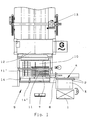
- the plate gluing machine shown in FIG. 1 is used for individual Making wooden panels. From a store or magazine 1 an operator removes lamellar wood 2 and places them on a transverse transport device 3, which the woods 2 against promotes a stop 4 transverse to its longitudinal direction. Be here the woods 2 are taken over by a transport device 6 (FIG. 2), which the woods 2 successively in their longitudinal direction of a stop device 5 feeds. During this transport, the woods 2 provided on one long side with a gluing device 8 with glue.
- each wood 2 in the basic version with a slide 9 transverse to its longitudinal direction pushed onto a cross conveyor 10 on which the with their Longitudinally adjacent wood 2 to a plate-shaped Lamella pack 11 can be put together in a known manner.
- the slider 9 is the next wood 2 with its glued Long side to the wood 2 already on the cross conveyor 8 or package 11 pressed in a known manner. That way the respective packages 11 are put together on the cross conveyor 10.
- the ejection movement taken over by two ejectors 31, 15.
- the package 11 As soon as the package 11 is pressed sufficiently, it is released and put together on the cross conveyor 10 during the pressing process new package 11 pushed into the press 12. There the package 11 previously pressed and dried in the press 12 pushed out by the following package to be pressed and pushed into a sawing device 13. Here is the package 11 if necessary sawn transversely to its longitudinal direction.
- the stop device 5 serves to put the timbers 2 in the correct position Able to position before using the slider 9 or the ejectors 31/15 are pushed onto the cross conveyor 10.
- the anchor device 5 has the stop 14 in the transport path of the Wood 2 lies. He is, as Fig. 1 shows, in the embodiment on the front end region of the transport device in the transport direction arranged.
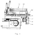
- An ejector 15 sits on a linear guide 16 which parallel to the transport direction of the wood 2 in the transport device 6 extends (Fig. 4).
- the stop 14 is with at least one Shoe 17 provided, with which it is positively on the linear guide 16 sits.
- the stop 14 can be manually along the linear guide 16 are moved into the desired stop position and locked, for example with a clamping screw.
- Fig. 1 shows the In case a second stop 14 'is set in one position, in which he has a greater distance from the stop 14. Accordingly are on the stop 14 'provided for the package 11 woods 2 stopped and with the slider 9 to form the package 11 pushed onto the cross conveyor 10.
- the stop 14 serves in this Trap as an attachment for much shorter timbers 2 with which one narrower package 11 'is put together.
- stop 14 it is also possible to motor the stop 14 to move to the desired position on the linear guide 16. In in this case, only a single stop 14 is required to be different put together wide packages.
- the adjustable stop 14, as shown in FIG. 5, has a stop plate 18, which lies in the transport path of the woods 2.
- the stop plate 18 is perpendicular to the direction of transport of the wood 2.
- the stop plate 18 is attached to an arm 19 which has one end parallel to one axis 20 lying to the transport direction of the timbers 2 can be pivoted is stored.
- the arm 19 is with a carriage 21 articulated, which sits on a linear guide 22, which is extends perpendicular to the linear guide 16.
- the carriage 21 has one upward arm 23 on which the end of a piston rod 24 attacks which is mounted in a cylinder 25 slidably. He is with its end facing away from the arm 23 on a holder 26 attached, which is held on a carrier 27 of the stop 14.
- the shoe 17 On the bottom of the carrier 27, the shoe 17 is provided with which the stop 14 can be adjusted along the linear guide 16.
- the swivel arm 19, the carriage 21 and the piston-cylinder arrangement 24, 25 are located in the area above the slide 9.
- the stop plate 18 is in the direction of displacement 28 before Slider 9.
- the Carriage 21 is reliably moved on the linear guide 22, whereby the piston rod 24 is pulled out of the cylinder 25.
- the Wood 2 initially remains until the slide 9 on the long side of the wood 2 comes to the plant and it moves further in Takes direction 28.
- the arm 19 around the axis 20 with a piston-cylinder unit 38 upwards pivoted, as shown in Fig. 4.
- the piston rod 24 is then acted upon with pressure medium so that it in the cylinder 25 is pushed back.
- the arm 19 remains with this Backward movement pivoted upwards.
- the slide 9 is also shown in FIG. 5 Starting position pushed back.
- the arm 19 with the piston-cylinder unit 38 is pivoted back into the starting position and the carriage 21 moved back on the linear guide 22. Now the next wood 2 can be fed until it starts the stop plate 18 comes to rest.
- This stop device 5 is for smaller outputs of the panel gluing machine suitable, for example for the supply of about 15 woods per minute. If higher performance is required, for example up to 60 timbers per minute, the next timber must can already be fed when the stop by the slide 9 has been moved in the direction of the cross conveyor 10.
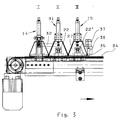
- the stop 14 and are on the linear guide 16 two ejectors 15, 31 arranged. 3 shows the stop 14 and the ejector 31 a structural unit. Both components 14, 31 are via a cross arm 32 which is parallel to the linear guide 16 extends, firmly connected.
- the ejector 15 is largely the same design as the stop 14 shown in FIG. 5. Instead the stop plate, the ejector 15 (Fig. 6) has a down protruding finger 33, which is close to the bearing surface of the timbers 2 is enough. Otherwise, the ejector 15 is of the same design as the Stop 14 according to FIG. 5.
- the ejector 15 also has the Carriage 21 ', which is movable on the linear guide 22'. Moreover the ejector 15 sits on the linear guide 16 so that it is vertical can be adjusted to the direction of displacement 28, in order to make it more concise Wood lengths to adjust.
- These three units 14, 31, 15 are used when in the Unit of time a larger number of woods 2 in the panel gluing machine to be promoted.
- the two ejectors 31, 15 are in the Starting position set so that the woods 2 in the area in front of the Fingers 33 of the two ejectors 31, 15 (Fig. 6) are transported can until they on the stop plate 18 of the stop 14 with their Come face to face.
- the carriages 21, 21 'of the ejector 31, 15 move in the direction of displacement 28, wherein the fingers 33 take the respective wood 2 along its long side and push on the cross conveyor 10 until the wood is already there formed package 11 is created.
- the piston rods 24 of the two ejectors 31, 15 are moved out of the cylinders 25.
- the slider 9 is only then moved by means of the chain drive 29, when the complete package 11 is put together on the cross conveyor 10 has been. Then the carriage 21, 21 'of the stop 14 and the ejector 15, 31 so far on the linear guides 22 moved that the stop plate 18 and the fingers 33 in Swivel clockwise around the respective axis 20. Then can the slider 9 to be moved to the package 11 in the Press 12 to move.
- a chain 34 is provided, which extends perpendicular to the chain 29 and to the linear guides 22.
- the stop 14 and the ejector 31 are firmly on the chain 34 attached. That is why they are chain 34 at the same time adjusted along the linear guide 16.
- the ejector 15 has an index bolt 35, which is preferably pneumatically operated and in the Chain 34 can be latched.
- the entire unit 14, 15, 31 first moves into the an end position of the stop device 5.
- the index bolt 35 of the Ejector 15 is retracted so that the ejector 15 from the Chain 34 is decoupled. Now the chain 34 is driven, whereby the stop 14 and the ejector 31 on the corresponding Length position of the wood 2 can be adjusted. Since the index bolt 35 is retracted, the ejector 15 remains during this adjustment process stand on the linear guide 16.
- the index bolt 35 is extended and thus the ejector 15 connected to the chain 34. Thereby the ejector 15 is also co-clamped by the chain 34, when the entire unit 14, 15, 31 moved to the eject position becomes.
- the index bolt 35 is accommodated in a holder 36 (Fig. 3), on the side facing away from the ejector 31 of the ejector 15 is arranged.
- the holder 36 is advantageously detachable from the Carrier 27 connected so that it can easily be replaced if necessary can be.
- a control device 37 is provided on the holder 36, with which the index bolt 35 can be operated.
Landscapes
- Engineering & Computer Science (AREA)
- Life Sciences & Earth Sciences (AREA)
- Manufacturing & Machinery (AREA)
- Wood Science & Technology (AREA)
- Forests & Forestry (AREA)
- Mechanical Engineering (AREA)
- Veneer Processing And Manufacture Of Plywood (AREA)
- Registering Or Overturning Sheets (AREA)
Abstract
Description
- Fig. 1
- in schematischer Darstellung eine Draufsicht auf eine Plattenverleimmaschine, vor der eine erfindungsgemäße Anschlageinrichtung angeordnet ist,
- Fig. 2
- eine Draufsicht auf einen Teil der erfindungsgemäßen Anschlageinrichtung,
- Fig. 3
- eine Rückansicht eines Teils der erfindungsgemäßen Anschlageinrichtung,
- Fig. 4
- in Seitenansicht einen motorisch verstellbaren Schwenkanschlag der erfindungsgemäßen Anschlageinrichtung,
- Fig. 5
- in Seitenansicht einen verstellbaren Schwenkanschlag der erfindungsgemäßen Anschlageinrichtung,
- Fig. 6
- in Seitenansicht einen Auswerfer der erfindungsgemäßen Anschlageinrichtung.
Claims (17)
- Anschlageinrichtung für eine Plattenverleimmaschine, mit wenigstens einem Anschlag für Hölzer und wenigstens einem Auswerfer, mit dem die Hölzer quer zu ihrer Zuführrichtung verschiebbar sind,
dadurch gekennzeichnet, daß der Anschlag (14) wenigstens ein Anschlagelement (18) aufweist, das in Auswerfrichtung (28) verschiebbar und um eine quer zur Auswerfrichtung (28) liegende Achse (20) schwenkbar ist. - Anschlageinrichtung nach Anspruch 1,
dadurch gekennzeichnet, daß das Anschlagelement (18) an einem Arm (19) vorgesehen ist, der um die Achse (20) schwenkbar ist. - Anschlageinrichtung nach Anspruch 2,
dadurch gekennzeichnet, daß der Arm (19) an einem Schlitten (21) angelenkt ist, der längs einer in Auswerfrichtung (28) sich erstreckenden Linearführung (22) des Anschlages (14) verschiebbar ist. - Anschlageinrichtung nach Anspruch 2 oder 3,
dadurch gekennzeichnet, daß am Arm (19) eine Kolbenstange (24) einer Kolben-Zylinder-Anordnung (25) angreift, die sich in Auswerfrichtung (28) erstreckt. - Anschlageinrichtung nach einem der Ansprüche 1 bis 4,
dadurch gekennzeichnet, daß der Anschlag (14) durch den Auswerfer (9) verschiebbar ist. - Anschlageinrichtung nach einem der Ansprüche 1 bis 5,
dadurch gekennzeichnet, daß das Anschlagelement (18) am Ende seines Verfahrweges aus dem Bewegungsweg des Auswerfers (9) verstellbar ist. - Anschlageinrichtung, insbesondere nach einem der Ansprüche 1 bis 6,
dadurch gekennzeichnet, daß der Anschlag (14) und der Auswerfer (31) gemeinsam mittels wenigstens eines Antriebes (34) quer zur Auswerfrichtung (28) verstellbar sind, und daß wenigstens ein weiterer Auswerfer (15) mit dem Antrieb (34) kuppelbar und von ihm entkuppelbar ist. - Anschlageinrichtung nach Anspruch 7,
dadurch gekennzeichnet, daß der weitere Auswerfer (15) wenigstens ein Kupplungselement (35), vorzugsweise einen Indexbolzen, aufweist. - Anschlageinrichtung nach Anspruch 8,
dadurch gekennzeichnet, daß das Kupplungselement (35) pneumatisch verstellbar ist. - Anschlageinrichtung nach einem der Ansprüche 7 bis 9,
dadurch gekennzeichnet, daß der Antrieb (34) eine Kette aufweist, in die das Kupplungselement (35) einhängbar ist. - Anschlageinrichtung nach einem der Ansprüche 7 bis 10,
dadurch gekennzeichnet, daß der Anschlag (14) und die beiden Auswerfer (15, 31) auf einer gemeinsamen Linearführung (16) quer zur Auswerfrichtung (28) verstellbar sind. - Anschlageinrichtung nach einem der Ansprüche 7 bis 11,
dadurch gekennzeichnet, daß die beiden Auswerfer (15, 31) jeweils wenigstens ein Auswerfelement (33), vorzugsweise einen Auswerffinger, aufweisen. - Anschlageinrichtung nach Anspruch 12,
dadurch gekennzeichnet, daß in Auswerfrichtung (28) hinter dem Auswerfelement (33) ein Schieber (9) angeordnet ist. - Anschlageinrichtung nach einem der Ansprüche 7 bis 13,
dadurch gekennzeichnet, daß der Anschlag (14) und der eine Auswerfer (31) miteinander verbunden sind. - Anschlageinrichtung nach einem der Ansprüche 12 bis 14,
dadurch gekennzeichnet, daß das Auswerfelement (33) am Arm (19) der Auswerfer (15, 31) vorgesehen ist. - Anschlageinrichtung nach einem der Ansprüche 7 bis 15,
dadurch gekennzeichnet, daß der Abstand zwischen den Auswerfern (15, 31) einstellbar ist. - Anschlageinrichtung nach Anspruch 16,
dadurch gekennzeichnet, daß der weitere Auswerfer (15) durch Ausklinken des Kupplungselementes (35) aus der Kette zur Abstandsveränderung vom Antrieb (34) entkuppelbar ist.
Applications Claiming Priority (2)
| Application Number | Priority Date | Filing Date | Title |
|---|---|---|---|
| DE10116695 | 2001-04-04 | ||
| DE2001116695 DE10116695A1 (de) | 2001-04-04 | 2001-04-04 | Anschlageinrichtung für eine Plattenverleimmaschine |
Publications (2)
| Publication Number | Publication Date |
|---|---|
| EP1247628A2 true EP1247628A2 (de) | 2002-10-09 |
| EP1247628A3 EP1247628A3 (de) | 2007-07-11 |
Family
ID=7680299
Family Applications (1)
| Application Number | Title | Priority Date | Filing Date |
|---|---|---|---|
| EP02007109A Withdrawn EP1247628A3 (de) | 2001-04-04 | 2002-03-28 | Anschlageinrichtung für eine Plattenverleimmaschine |
Country Status (2)
| Country | Link |
|---|---|
| EP (1) | EP1247628A3 (de) |
| DE (1) | DE10116695A1 (de) |
Cited By (3)
| Publication number | Priority date | Publication date | Assignee | Title |
|---|---|---|---|---|
| WO2008064799A1 (de) * | 2006-11-27 | 2008-06-05 | Nkt Neue-Keilzink-Technologie | Presse zum stirnseitigen verpressen von schnitthölzern |
| EP3795315A1 (de) | 2019-09-19 | 2021-03-24 | Gregor Ledinek | Automatische maschine zur breitenverleimung von holzlamellen zu laminierten platten beliebiger abmessungen und zugehöriges verfahren |
| CN116787562A (zh) * | 2023-08-08 | 2023-09-22 | 大连工业大学 | 一种人造板预压机 |
Family Cites Families (2)
| Publication number | Priority date | Publication date | Assignee | Title |
|---|---|---|---|---|
| BE527403A (de) * | 1953-03-19 | |||
| AT405037B (de) * | 1996-06-14 | 1999-04-26 | Schilcher Industrieanlagen Und | Produktionsanlage zur herstellung eines aus stab- bzw. brettförmigen lamellen bestehenden rohprofiles |
-
2001
- 2001-04-04 DE DE2001116695 patent/DE10116695A1/de not_active Withdrawn
-
2002
- 2002-03-28 EP EP02007109A patent/EP1247628A3/de not_active Withdrawn
Cited By (4)
| Publication number | Priority date | Publication date | Assignee | Title |
|---|---|---|---|---|
| WO2008064799A1 (de) * | 2006-11-27 | 2008-06-05 | Nkt Neue-Keilzink-Technologie | Presse zum stirnseitigen verpressen von schnitthölzern |
| EP3795315A1 (de) | 2019-09-19 | 2021-03-24 | Gregor Ledinek | Automatische maschine zur breitenverleimung von holzlamellen zu laminierten platten beliebiger abmessungen und zugehöriges verfahren |
| US11338470B2 (en) | 2019-09-19 | 2022-05-24 | Gregor Ledinek | Automatic machine for width gluing of wooden lamellas into laminated plates of optional dimensions and a method relating thereto |
| CN116787562A (zh) * | 2023-08-08 | 2023-09-22 | 大连工业大学 | 一种人造板预压机 |
Also Published As
| Publication number | Publication date |
|---|---|
| DE10116695A1 (de) | 2002-10-10 |
| EP1247628A3 (de) | 2007-07-11 |
Similar Documents
| Publication | Publication Date | Title |
|---|---|---|
| DE102007010207B4 (de) | Plattenaufteilanlage zum Aufteilen von plattenförmigen Werkstücken, sowie Verfahren zu deren Betrieb | |
| EP2243606B1 (de) | Anlage zur Herstellung von Platten aus Lamellen aus Holz sowie Verfahren zur Herstellung solcher Platten | |
| EP1600254B1 (de) | Vorschubeinheit für eine Maschine zum Bearbeiten von Werkstücken sowie Verfahren zum Bearbeiten solcher Werkstücke | |
| AT396890B (de) | Vorrichtung zum abstützen eines auf einer plattenaufteilsäge hergestellten langen und schmalen werkstückpakets | |
| DE4116769C2 (de) | Doppelgehrungssäge | |
| DE2312376C2 (de) | Aufteilsägemaschine | |
| EP1247628A2 (de) | Anschlageinrichtung für eine Plattenverleimmaschine | |
| DE4341864C2 (de) | Vorrichtung zum Entfernen von Schweißwülsten von Kunststoffpaletten und dabei verwendete Schneidvorrichtungen | |
| DE2828210C2 (de) | Vorrichtung zum Vereinzeln stirnseitig keilgezinkter Bretter aus einem Paket und zum Zusammenfügen zu einem Strang | |
| DE3027873A1 (de) | Vorrichtung zum zusammennageln von aus mehreren bretterschichten bestehenden schalungsplatten | |
| AT402273B (de) | Bandsäge für das schneiden von stämmen | |
| DE1728226C3 (de) | Verfahren und Vorrichtung zum Beschicken einer Etagenwarmpresse für Sperrholz, Hartfaserplatten und dergleichen | |
| AT402052B (de) | Einrichtung zum ausrichten und stapeln von formatzuschnitten | |
| DE19518458A1 (de) | Einlaufvorrichtung zur Zuführung von Werkstücken | |
| DE1286738B (de) | Einrichtung zum Verbinden von Werkstuecken an ihren Stirnenden mittels eines Bindemittels, insbesondere von Werkstuecken aus Holz | |
| AT522336B1 (de) | Vorrichtung zum digitalen Bedrucken einer Profilleiste | |
| DE19912171C2 (de) | Holzlattenstapelvorrichtung | |
| DE102023101981A1 (de) | Keilzinkanlage und Verbindungsstation für Keilzinkanlage | |
| DE3616921C2 (de) | ||
| AT225403B (de) | Formatsäge | |
| DE2149964C3 (de) | Vorrichtung zum Montieren von Griffleisten in Möbeltüren | |
| DE102005020745A1 (de) | Verfahren zur Herstellung von Auflagesätteln, Maschine und Sattel | |
| DE2502864C3 (de) | Vorrichtung zum Queraufteilen einer Platte | |
| DE2228373B1 (de) | Verfahren zum verleimen von brettern zu einem fortlaufenden plattenband und durchlauf-fugenverleimpresse hierfuer | |
| DE102012111879A1 (de) | Verfahren und Vorrichtung zum Bearbeiten von Platten |
Legal Events
| Date | Code | Title | Description |
|---|---|---|---|
| PUAI | Public reference made under article 153(3) epc to a published international application that has entered the european phase |
Free format text: ORIGINAL CODE: 0009012 |
|
| AK | Designated contracting states |
Kind code of ref document: A2 Designated state(s): AT BE CH CY DE DK ES FI FR GB GR IE IT LI LU MC NL PT SE TR |
|
| AX | Request for extension of the european patent |
Free format text: AL;LT;LV;MK;RO;SI |
|
| PUAL | Search report despatched |
Free format text: ORIGINAL CODE: 0009013 |
|
| AK | Designated contracting states |
Kind code of ref document: A3 Designated state(s): AT BE CH CY DE DK ES FI FR GB GR IE IT LI LU MC NL PT SE TR |
|
| AX | Request for extension of the european patent |
Extension state: AL LT LV MK RO SI |
|
| STAA | Information on the status of an ep patent application or granted ep patent |
Free format text: STATUS: THE APPLICATION IS DEEMED TO BE WITHDRAWN |
|
| AKX | Designation fees paid | ||
| 18D | Application deemed to be withdrawn |
Effective date: 20071002 |
|
| REG | Reference to a national code |
Ref country code: DE Ref legal event code: 8566 |