EP1248064A1 - Wärmeübertrager - Google Patents
Wärmeübertrager Download PDFInfo
- Publication number
- EP1248064A1 EP1248064A1 EP02007439A EP02007439A EP1248064A1 EP 1248064 A1 EP1248064 A1 EP 1248064A1 EP 02007439 A EP02007439 A EP 02007439A EP 02007439 A EP02007439 A EP 02007439A EP 1248064 A1 EP1248064 A1 EP 1248064A1
- Authority
- EP
- European Patent Office
- Prior art keywords
- spirals
- pipe
- heat exchanger
- distributor
- pipes
- Prior art date
- Legal status (The legal status is an assumption and is not a legal conclusion. Google has not performed a legal analysis and makes no representation as to the accuracy of the status listed.)
- Granted
Links
- 238000010521 absorption reaction Methods 0.000 description 4
- 238000005057 refrigeration Methods 0.000 description 4
- 239000006096 absorbing agent Substances 0.000 description 2
- 238000009434 installation Methods 0.000 description 2
- AMXOYNBUYSYVKV-UHFFFAOYSA-M lithium bromide Chemical compound [Li+].[Br-] AMXOYNBUYSYVKV-UHFFFAOYSA-M 0.000 description 2
- 238000004519 manufacturing process Methods 0.000 description 2
- 230000002411 adverse Effects 0.000 description 1
- 238000010276 construction Methods 0.000 description 1
- 239000000498 cooling water Substances 0.000 description 1
- 230000000694 effects Effects 0.000 description 1
- 230000008030 elimination Effects 0.000 description 1
- 238000003379 elimination reaction Methods 0.000 description 1
- 239000008236 heating water Substances 0.000 description 1
- 238000010348 incorporation Methods 0.000 description 1
- 230000010354 integration Effects 0.000 description 1
- 238000012423 maintenance Methods 0.000 description 1
- 238000000926 separation method Methods 0.000 description 1
- 239000007921 spray Substances 0.000 description 1
- 238000005507 spraying Methods 0.000 description 1
Images

Classifications
-
- F—MECHANICAL ENGINEERING; LIGHTING; HEATING; WEAPONS; BLASTING
- F28—HEAT EXCHANGE IN GENERAL
- F28D—HEAT-EXCHANGE APPARATUS, NOT PROVIDED FOR IN ANOTHER SUBCLASS, IN WHICH THE HEAT-EXCHANGE MEDIA DO NOT COME INTO DIRECT CONTACT
- F28D7/00—Heat-exchange apparatus having stationary tubular conduit assemblies for both heat-exchange media, the media being in contact with different sides of a conduit wall
- F28D7/04—Heat-exchange apparatus having stationary tubular conduit assemblies for both heat-exchange media, the media being in contact with different sides of a conduit wall the conduits being spirally coiled
Definitions
- the invention relates to a heat exchanger, in particular for use in absorption refrigeration systems suitable is.
- Heat exchangers of known design for absorption refrigeration systems consist of horizontal Tube bundles that are rolled or welded into tube sheets on both sides. Such Execution is z. B. described in US 5 463 880 A. In these embodiments it is problematic to compensate for the differences in length caused by thermal expansion. In addition, it is relatively expensive to distribute the solution evenly to ensure the tube bundle. This requires trickle trays with a variety of holes and other spray devices, such as. B. according to US 5 463 880 A, over the entire Pipe bundles are distributed, which means a high level of construction and maintenance The openings have been cleaned.
- the object of the invention is therefore to find a solution that allows, if possible to arrange a large number of pipe spirals in a small space and yet a simple one Allow assembly.
- the object is achieved by the features of the claim, by arrangement the collecting and distribution pipes on the outer circumference of the spiral, the pipe spiral on the outside Manifold begins spiraling inward, reverses near the center and in the radial gaps of the spiral led out again in opposite directions and opens into the collecting tube. That presupposes that the radial distance between the spiral turns is slightly larger than the pipe diameter.
- the spiral can be made from two symmetrical parts. These single spirals are inserted into each other in mirror image and in the middle by a suitable piece of pipe connected with each other.
- the overall height is minimized by arranging them vertically one below the other Spirals with their ends leading outwards alternately from left and right can be integrated into a distributor or manifold.
- the same effect is achieved through the Separation of collecting and distribution pipes into several, but at least two individual pipes achieved.
- the spiral ends leading outwards are alternately divided into different and manifolds integrated.
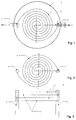
- Fig. 1 shows how a tube spiral 2 housed in a container 1 and with the ends in a manifold 4 and a manifold 3 is integrated.
- 1 begins the first Pipe spiral 2 in the distribution pipe 3 and ends in the same plane in the collecting pipe 4.
- the second Pipe spiral 5 is arranged in mirror image and begins according to FIG. 2 in the collecting pipe 4 and ends in the distributor pipe 3. From FIG. 3 it can be seen how through the mutual integration of the pipe spirals 2 and 5 there is twice the installation distance at the connection point, while the pipe spirals 2 and 5 are only a simple distance apart vertically.
- the pipe spiral 4 is the incorporation of the pipe spirals into several distributor and collecting pipes 3 and 4 shown.
- the upper tube spiral 2 begins in the first distributor tube 3 and ends in the same Level in the first collecting tube 4.
- the tube spiral 5 underneath begins in the second distributor pipe 3 and ends in the second header pipe 4. Also at this embodiment is sufficient with minimal vertical expansion of the tube bundle Space for the installation of the individual spirals gained.
- the individual manifolds and manifolds 3 and 4 are each connected and have a common inflow and outflow.
Landscapes
- Engineering & Computer Science (AREA)
- Physics & Mathematics (AREA)
- Thermal Sciences (AREA)
- Mechanical Engineering (AREA)
- General Engineering & Computer Science (AREA)
- Heat-Exchange Devices With Radiators And Conduit Assemblies (AREA)
- Power Steering Mechanism (AREA)
- Compression-Type Refrigeration Machines With Reversible Cycles (AREA)
- Separation By Low-Temperature Treatments (AREA)
Abstract
Description
Claims (5)
- Wärmeübertrager mit übereinander angeordneten Rohrspiralen (2) und (5), die jeweils in ein gemeinsames Verteilerrohr (3) bzw. Sammelrohr (4) münden, dadurch gekennzeichnet, dass die Rohrspiralen (2) und (5) als Doppelspiralen ausgebildet sind, die von einem Punkt am Außenumfang nach innen verlaufen und sich in der Nähe des Zentrums umkehren und in den radialen Zwischenräumen in gleicher Ebene wieder nach außen geführt werden.
- Wärmeübertrager nach Anspruch 1, dadurch gekennzeichnet, dass die untereinander liegenden Rohrspiralen (2) und (5) jeweils spiegelbildlich angeordnet sind und damit mit ihren Enden abwechselnd entgegengesetzt in das Verteilerrohr (3) bzw. Sammelrohr (5) eingebunden sind.
- Wärmeübertrager nach Anspruch 1, dadurch gekennzeichnet, dass zwei Verteilerrohre (3) und Sammelrohre (4) angeordnet sind und die Rohrspiralen (2) und (5) jeweils abwechselnd in die einzelnen Verteiler- bzw. Sammelrohre (2 bzw. 5) eingebunden sind.
- Wärmeübertrager nach Anspruch 3, dadurch gekennzeichnet, dass die einzelnen Verteilerrohre (3) und Sammelrohre (4) miteinander verbunden sind und jeweils einen gemeinsamen Zu- und Ablauf haben.
- Wärmeübertrager nach Anspruch 1, dadurch gekennzeichnet, dass die als Doppelspiralen ausgebildeten Rohrspiralen (2) und (5) aus jeweils zwei symmetrischen Teilspiralen bestehen, die spiegelbildlich ineinander angeordnet und in der Mitte durch eine Rohrverbindung zusammengefügt sind.
Applications Claiming Priority (2)
| Application Number | Priority Date | Filing Date | Title |
|---|---|---|---|
| DE10116949A DE10116949A1 (de) | 2001-04-05 | 2001-04-05 | Wärmeübertrager |
| DE10116949 | 2001-04-05 |
Publications (2)
| Publication Number | Publication Date |
|---|---|
| EP1248064A1 true EP1248064A1 (de) | 2002-10-09 |
| EP1248064B1 EP1248064B1 (de) | 2009-05-13 |
Family
ID=7680473
Family Applications (1)
| Application Number | Title | Priority Date | Filing Date |
|---|---|---|---|
| EP02007439A Expired - Lifetime EP1248064B1 (de) | 2001-04-05 | 2002-03-30 | Wärmeübertrager |
Country Status (3)
| Country | Link |
|---|---|
| EP (1) | EP1248064B1 (de) |
| AT (1) | ATE431534T1 (de) |
| DE (2) | DE10116949A1 (de) |
Cited By (4)
| Publication number | Priority date | Publication date | Assignee | Title |
|---|---|---|---|---|
| WO2004109209A1 (de) * | 2003-05-30 | 2004-12-16 | Eaw-Anlagenbau Gmbh Westenfeld | Vorrichtung zur wärmeübertragung |
| WO2006045551A3 (de) * | 2004-10-26 | 2006-08-17 | Rohr Alex Von | Energiespeicher, wärmetauscheranordnung für einen energiespeicher, energiespeichersystem sowie verfahren dazu |
| FR2962201A1 (fr) * | 2010-07-02 | 2012-01-06 | France Etat | Echangeur de chaleur a tubes d'alimentation et de retour internes |
| WO2012049318A1 (de) * | 2010-10-15 | 2012-04-19 | Behr Gmbh & Co. Kg | Wärmetauscher |
Families Citing this family (1)
| Publication number | Priority date | Publication date | Assignee | Title |
|---|---|---|---|---|
| DE102005059667A1 (de) * | 2005-12-12 | 2007-06-14 | Valeo Systemes Thermiques, La Verriere | Wärmetauscher mit einer Mehrzahl von Rohrelementen |
Citations (4)
| Publication number | Priority date | Publication date | Assignee | Title |
|---|---|---|---|---|
| DE962169C (de) * | 1953-12-07 | 1957-04-18 | Bronswerk Nv | Waermeaustauscher mit einer Heizflaeche, bestehend aus einer Anzahl von uebereinander in einem teilbaren zylindrischen Mantel angeordneten, zu platten Doppelspiralen gebogenen Rohren |
| DE1060882B (de) * | 1956-01-26 | 1959-07-09 | Siemens Ag | Dreistoffwaermetauscher fuer Waermekraftanlagen, insbesondere Atomkraftanlagen |
| GB846592A (en) * | 1957-11-06 | 1960-08-31 | Marston Excelsior Ltd | Heat exchange apparatus |
| DE19802670A1 (de) * | 1998-01-24 | 1999-09-09 | Inst Luft Kaeltetech Gem Gmbh | Wärmeübertrager |
-
2001
- 2001-04-05 DE DE10116949A patent/DE10116949A1/de not_active Withdrawn
-
2002
- 2002-03-30 EP EP02007439A patent/EP1248064B1/de not_active Expired - Lifetime
- 2002-03-30 AT AT02007439T patent/ATE431534T1/de active
- 2002-03-30 DE DE50213537T patent/DE50213537D1/de not_active Expired - Lifetime
Patent Citations (4)
| Publication number | Priority date | Publication date | Assignee | Title |
|---|---|---|---|---|
| DE962169C (de) * | 1953-12-07 | 1957-04-18 | Bronswerk Nv | Waermeaustauscher mit einer Heizflaeche, bestehend aus einer Anzahl von uebereinander in einem teilbaren zylindrischen Mantel angeordneten, zu platten Doppelspiralen gebogenen Rohren |
| DE1060882B (de) * | 1956-01-26 | 1959-07-09 | Siemens Ag | Dreistoffwaermetauscher fuer Waermekraftanlagen, insbesondere Atomkraftanlagen |
| GB846592A (en) * | 1957-11-06 | 1960-08-31 | Marston Excelsior Ltd | Heat exchange apparatus |
| DE19802670A1 (de) * | 1998-01-24 | 1999-09-09 | Inst Luft Kaeltetech Gem Gmbh | Wärmeübertrager |
Cited By (4)
| Publication number | Priority date | Publication date | Assignee | Title |
|---|---|---|---|---|
| WO2004109209A1 (de) * | 2003-05-30 | 2004-12-16 | Eaw-Anlagenbau Gmbh Westenfeld | Vorrichtung zur wärmeübertragung |
| WO2006045551A3 (de) * | 2004-10-26 | 2006-08-17 | Rohr Alex Von | Energiespeicher, wärmetauscheranordnung für einen energiespeicher, energiespeichersystem sowie verfahren dazu |
| FR2962201A1 (fr) * | 2010-07-02 | 2012-01-06 | France Etat | Echangeur de chaleur a tubes d'alimentation et de retour internes |
| WO2012049318A1 (de) * | 2010-10-15 | 2012-04-19 | Behr Gmbh & Co. Kg | Wärmetauscher |
Also Published As
| Publication number | Publication date |
|---|---|
| DE10116949A1 (de) | 2002-10-17 |
| EP1248064B1 (de) | 2009-05-13 |
| DE50213537D1 (de) | 2009-06-25 |
| ATE431534T1 (de) | 2009-05-15 |
Similar Documents
| Publication | Publication Date | Title |
|---|---|---|
| DE69215277T2 (de) | Wärmetauscher in Modulbauweise | |
| DE3856032T2 (de) | Wärmetauscher mit verbesserter Kondensatsammlung | |
| DE69509469T2 (de) | Kühlmittelverdampfer | |
| DE2847525C3 (de) | Wärmetauscher für Verdampfer, insbesondere für Klimaanlagen | |
| DE102005058769B4 (de) | Ladeluftkühler | |
| EP1273864B1 (de) | Wärmetauscher | |
| DE69600489T2 (de) | Wärmetauscher mit abgeteilter Endkammer | |
| EP0964218A2 (de) | Wärmetauscher mit verrippten Flachrohren, insbesondere Heizungswärmetauscher, Motorkühler, Verflüssiger oder Verdampfer, für Kraftfahrzeuge | |
| DE68904469T2 (de) | Waermetauscher. | |
| DE102004011608A1 (de) | Wärmetauscher einer Fahrzeugklimaanlage | |
| EP2825832A2 (de) | Wärmeübertrager | |
| EP1248064B1 (de) | Wärmeübertrager | |
| EP2795219A2 (de) | Modularer wärmetauscher | |
| DE3318722A1 (de) | Waermetauscher | |
| DE4213509A1 (de) | Wärmetauscher, insbesondere Kondensator für Fahrzeug-Klimaanlagen | |
| EP0401543B1 (de) | Wärmeübertrager, insbesondere für einen gas- oder ölbeheizten Wassererhitzer | |
| DE19802670C2 (de) | Wärmeübertrager | |
| EP2881693A1 (de) | Wärmetauscher für Haushaltsgeräte wie beispielsweise Wäschetrockner, Geschirrspüler oder Waschtrockner | |
| EP0223912B1 (de) | Vorrichtung zum Kühlen von heissen, staubbeladenen Gasen | |
| DE102004018317A1 (de) | Wärmeübertrager für Kraftfahrzeuge | |
| DE112022002038T5 (de) | Wärmetauscher | |
| DE3247392A1 (de) | Waermeuebertrager | |
| DE19957307A1 (de) | Zweikreis-Wärmeübertrager | |
| DE4222663C2 (de) | Heizregister, insbesondere für Trockeneinrichtungen | |
| DE4409920C2 (de) | Einrichtung zur Führung des Kältemittels in einem liegenden Rohrbündelverdampfer mit U-Rohren |
Legal Events
| Date | Code | Title | Description |
|---|---|---|---|
| PUAI | Public reference made under article 153(3) epc to a published international application that has entered the european phase |
Free format text: ORIGINAL CODE: 0009012 |
|
| AK | Designated contracting states |
Kind code of ref document: A1 Designated state(s): AT BE CH CY DE DK ES FI FR GB GR IE IT LI LU MC NL PT SE TR |
|
| AX | Request for extension of the european patent |
Free format text: AL;LT;LV;MK;RO;SI |
|
| 17P | Request for examination filed |
Effective date: 20030404 |
|
| AKX | Designation fees paid |
Designated state(s): AT BE CH CY DE DK ES FI FR GB GR IE IT LI LU MC NL PT SE TR |
|
| 17Q | First examination report despatched |
Effective date: 20050411 |
|
| GRAP | Despatch of communication of intention to grant a patent |
Free format text: ORIGINAL CODE: EPIDOSNIGR1 |
|
| GRAS | Grant fee paid |
Free format text: ORIGINAL CODE: EPIDOSNIGR3 |
|
| GRAA | (expected) grant |
Free format text: ORIGINAL CODE: 0009210 |
|
| AK | Designated contracting states |
Kind code of ref document: B1 Designated state(s): AT BE CH CY DE DK ES FI FR GB GR IE IT LI LU MC NL PT SE TR |
|
| REG | Reference to a national code |
Ref country code: GB Ref legal event code: FG4D Free format text: NOT ENGLISH |
|
| REG | Reference to a national code |
Ref country code: CH Ref legal event code: EP |
|
| REG | Reference to a national code |
Ref country code: IE Ref legal event code: FG4D |
|
| REF | Corresponds to: |
Ref document number: 50213537 Country of ref document: DE Date of ref document: 20090625 Kind code of ref document: P |
|
| PG25 | Lapsed in a contracting state [announced via postgrant information from national office to epo] |
Ref country code: PT Free format text: LAPSE BECAUSE OF FAILURE TO SUBMIT A TRANSLATION OF THE DESCRIPTION OR TO PAY THE FEE WITHIN THE PRESCRIBED TIME-LIMIT Effective date: 20090913 Ref country code: FI Free format text: LAPSE BECAUSE OF FAILURE TO SUBMIT A TRANSLATION OF THE DESCRIPTION OR TO PAY THE FEE WITHIN THE PRESCRIBED TIME-LIMIT Effective date: 20090513 Ref country code: ES Free format text: LAPSE BECAUSE OF FAILURE TO SUBMIT A TRANSLATION OF THE DESCRIPTION OR TO PAY THE FEE WITHIN THE PRESCRIBED TIME-LIMIT Effective date: 20090824 |
|
| NLV1 | Nl: lapsed or annulled due to failure to fulfill the requirements of art. 29p and 29m of the patents act | ||
| PG25 | Lapsed in a contracting state [announced via postgrant information from national office to epo] |
Ref country code: NL Free format text: LAPSE BECAUSE OF FAILURE TO SUBMIT A TRANSLATION OF THE DESCRIPTION OR TO PAY THE FEE WITHIN THE PRESCRIBED TIME-LIMIT Effective date: 20090513 Ref country code: SE Free format text: LAPSE BECAUSE OF FAILURE TO SUBMIT A TRANSLATION OF THE DESCRIPTION OR TO PAY THE FEE WITHIN THE PRESCRIBED TIME-LIMIT Effective date: 20090813 |
|
| REG | Reference to a national code |
Ref country code: IE Ref legal event code: FD4D |
|
| PG25 | Lapsed in a contracting state [announced via postgrant information from national office to epo] |
Ref country code: IE Free format text: LAPSE BECAUSE OF FAILURE TO SUBMIT A TRANSLATION OF THE DESCRIPTION OR TO PAY THE FEE WITHIN THE PRESCRIBED TIME-LIMIT Effective date: 20090513 Ref country code: DK Free format text: LAPSE BECAUSE OF FAILURE TO SUBMIT A TRANSLATION OF THE DESCRIPTION OR TO PAY THE FEE WITHIN THE PRESCRIBED TIME-LIMIT Effective date: 20090513 |
|
| PLBE | No opposition filed within time limit |
Free format text: ORIGINAL CODE: 0009261 |
|
| STAA | Information on the status of an ep patent application or granted ep patent |
Free format text: STATUS: NO OPPOSITION FILED WITHIN TIME LIMIT |
|
| 26N | No opposition filed |
Effective date: 20100216 |
|
| BERE | Be: lapsed |
Owner name: WEGRA ANLAGENBAU G.M.B.H. Effective date: 20100331 Owner name: INSTITUT FUR LUFT- UND KALTETECHNIK GEMEINNUTZIGE Effective date: 20100331 |
|
| PG25 | Lapsed in a contracting state [announced via postgrant information from national office to epo] |
Ref country code: GR Free format text: LAPSE BECAUSE OF FAILURE TO SUBMIT A TRANSLATION OF THE DESCRIPTION OR TO PAY THE FEE WITHIN THE PRESCRIBED TIME-LIMIT Effective date: 20090814 Ref country code: MC Free format text: LAPSE BECAUSE OF NON-PAYMENT OF DUE FEES Effective date: 20100331 |
|
| REG | Reference to a national code |
Ref country code: CH Ref legal event code: PL |
|
| GBPC | Gb: european patent ceased through non-payment of renewal fee |
Effective date: 20100330 |
|
| REG | Reference to a national code |
Ref country code: FR Ref legal event code: ST Effective date: 20101130 |
|
| PG25 | Lapsed in a contracting state [announced via postgrant information from national office to epo] |
Ref country code: FR Free format text: LAPSE BECAUSE OF NON-PAYMENT OF DUE FEES Effective date: 20100331 |
|
| PG25 | Lapsed in a contracting state [announced via postgrant information from national office to epo] |
Ref country code: LI Free format text: LAPSE BECAUSE OF NON-PAYMENT OF DUE FEES Effective date: 20100331 Ref country code: BE Free format text: LAPSE BECAUSE OF NON-PAYMENT OF DUE FEES Effective date: 20100331 Ref country code: CH Free format text: LAPSE BECAUSE OF NON-PAYMENT OF DUE FEES Effective date: 20100331 |
|
| PG25 | Lapsed in a contracting state [announced via postgrant information from national office to epo] |
Ref country code: GB Free format text: LAPSE BECAUSE OF NON-PAYMENT OF DUE FEES Effective date: 20100330 |
|
| PGFP | Annual fee paid to national office [announced via postgrant information from national office to epo] |
Ref country code: IT Payment date: 20120327 Year of fee payment: 11 |
|
| PG25 | Lapsed in a contracting state [announced via postgrant information from national office to epo] |
Ref country code: CY Free format text: LAPSE BECAUSE OF FAILURE TO SUBMIT A TRANSLATION OF THE DESCRIPTION OR TO PAY THE FEE WITHIN THE PRESCRIBED TIME-LIMIT Effective date: 20090513 |
|
| PG25 | Lapsed in a contracting state [announced via postgrant information from national office to epo] |
Ref country code: LU Free format text: LAPSE BECAUSE OF NON-PAYMENT OF DUE FEES Effective date: 20100330 |
|
| PG25 | Lapsed in a contracting state [announced via postgrant information from national office to epo] |
Ref country code: TR Free format text: LAPSE BECAUSE OF FAILURE TO SUBMIT A TRANSLATION OF THE DESCRIPTION OR TO PAY THE FEE WITHIN THE PRESCRIBED TIME-LIMIT Effective date: 20090513 |
|
| PGFP | Annual fee paid to national office [announced via postgrant information from national office to epo] |
Ref country code: AT Payment date: 20120321 Year of fee payment: 11 |
|
| REG | Reference to a national code |
Ref country code: AT Ref legal event code: MM01 Ref document number: 431534 Country of ref document: AT Kind code of ref document: T Effective date: 20130330 |
|
| PG25 | Lapsed in a contracting state [announced via postgrant information from national office to epo] |
Ref country code: AT Free format text: LAPSE BECAUSE OF NON-PAYMENT OF DUE FEES Effective date: 20130330 |
|
| PG25 | Lapsed in a contracting state [announced via postgrant information from national office to epo] |
Ref country code: IT Free format text: LAPSE BECAUSE OF NON-PAYMENT OF DUE FEES Effective date: 20130330 |
|
| PGFP | Annual fee paid to national office [announced via postgrant information from national office to epo] |
Ref country code: DE Payment date: 20170511 Year of fee payment: 16 |
|
| REG | Reference to a national code |
Ref country code: DE Ref legal event code: R119 Ref document number: 50213537 Country of ref document: DE |
|
| PG25 | Lapsed in a contracting state [announced via postgrant information from national office to epo] |
Ref country code: DE Free format text: LAPSE BECAUSE OF NON-PAYMENT OF DUE FEES Effective date: 20181002 |