EP1251025A2 - Driving aiding system - Google Patents
Driving aiding system Download PDFInfo
- Publication number
- EP1251025A2 EP1251025A2 EP02007712A EP02007712A EP1251025A2 EP 1251025 A2 EP1251025 A2 EP 1251025A2 EP 02007712 A EP02007712 A EP 02007712A EP 02007712 A EP02007712 A EP 02007712A EP 1251025 A2 EP1251025 A2 EP 1251025A2
- Authority
- EP
- European Patent Office
- Prior art keywords
- image
- vehicle
- hitch
- displaying
- screen
- Prior art date
- Legal status (The legal status is an assumption and is not a legal conclusion. Google has not performed a legal analysis and makes no representation as to the accuracy of the status listed.)
- Granted
Links
Images


Classifications
-
- B—PERFORMING OPERATIONS; TRANSPORTING
- B62—LAND VEHICLES FOR TRAVELLING OTHERWISE THAN ON RAILS
- B62D—MOTOR VEHICLES; TRAILERS
- B62D15/00—Steering not otherwise provided for
- B62D15/02—Steering position indicators ; Steering position determination; Steering aids
- B62D15/029—Steering assistants using warnings or proposing actions to the driver without influencing the steering system
-
- B—PERFORMING OPERATIONS; TRANSPORTING
- B60—VEHICLES IN GENERAL
- B60D—VEHICLE CONNECTIONS
- B60D1/00—Traction couplings; Hitches; Draw-gear; Towing devices
- B60D1/24—Traction couplings; Hitches; Draw-gear; Towing devices characterised by arrangements for particular functions
- B60D1/36—Traction couplings; Hitches; Draw-gear; Towing devices characterised by arrangements for particular functions for facilitating connection, e.g. hitch catchers
-
- B—PERFORMING OPERATIONS; TRANSPORTING
- B60—VEHICLES IN GENERAL
- B60K—ARRANGEMENT OR MOUNTING OF PROPULSION UNITS OR OF TRANSMISSIONS IN VEHICLES; ARRANGEMENT OR MOUNTING OF PLURAL DIVERSE PRIME-MOVERS IN VEHICLES; AUXILIARY DRIVES FOR VEHICLES; INSTRUMENTATION OR DASHBOARDS FOR VEHICLES; ARRANGEMENTS IN CONNECTION WITH COOLING, AIR INTAKE, GAS EXHAUST OR FUEL SUPPLY OF PROPULSION UNITS IN VEHICLES
- B60K35/00—Instruments specially adapted for vehicles; Arrangement of instruments in or on vehicles
- B60K35/20—Output arrangements, i.e. from vehicle to user, associated with vehicle functions or specially adapted therefor
- B60K35/21—Output arrangements, i.e. from vehicle to user, associated with vehicle functions or specially adapted therefor using visual output, e.g. blinking lights or matrix displays
- B60K35/22—Display screens
-
- B—PERFORMING OPERATIONS; TRANSPORTING
- B60—VEHICLES IN GENERAL
- B60K—ARRANGEMENT OR MOUNTING OF PROPULSION UNITS OR OF TRANSMISSIONS IN VEHICLES; ARRANGEMENT OR MOUNTING OF PLURAL DIVERSE PRIME-MOVERS IN VEHICLES; AUXILIARY DRIVES FOR VEHICLES; INSTRUMENTATION OR DASHBOARDS FOR VEHICLES; ARRANGEMENTS IN CONNECTION WITH COOLING, AIR INTAKE, GAS EXHAUST OR FUEL SUPPLY OF PROPULSION UNITS IN VEHICLES
- B60K35/00—Instruments specially adapted for vehicles; Arrangement of instruments in or on vehicles
- B60K35/20—Output arrangements, i.e. from vehicle to user, associated with vehicle functions or specially adapted therefor
- B60K35/28—Output arrangements, i.e. from vehicle to user, associated with vehicle functions or specially adapted therefor characterised by the type of the output information, e.g. video entertainment or vehicle dynamics information; characterised by the purpose of the output information, e.g. for attracting the attention of the driver
-
- B—PERFORMING OPERATIONS; TRANSPORTING
- B60—VEHICLES IN GENERAL
- B60K—ARRANGEMENT OR MOUNTING OF PROPULSION UNITS OR OF TRANSMISSIONS IN VEHICLES; ARRANGEMENT OR MOUNTING OF PLURAL DIVERSE PRIME-MOVERS IN VEHICLES; AUXILIARY DRIVES FOR VEHICLES; INSTRUMENTATION OR DASHBOARDS FOR VEHICLES; ARRANGEMENTS IN CONNECTION WITH COOLING, AIR INTAKE, GAS EXHAUST OR FUEL SUPPLY OF PROPULSION UNITS IN VEHICLES
- B60K35/00—Instruments specially adapted for vehicles; Arrangement of instruments in or on vehicles
- B60K35/65—Instruments specially adapted for specific vehicle types or users, e.g. for left- or right-hand drive
- B60K35/654—Instruments specially adapted for specific vehicle types or users, e.g. for left- or right-hand drive the user being the driver
-
- G—PHYSICS
- G08—SIGNALLING
- G08G—TRAFFIC CONTROL SYSTEMS
- G08G1/00—Traffic control systems for road vehicles
- G08G1/16—Anti-collision systems
- G08G1/165—Anti-collision systems for passive traffic, e.g. including static obstacles, trees
-
- B—PERFORMING OPERATIONS; TRANSPORTING
- B60—VEHICLES IN GENERAL
- B60K—ARRANGEMENT OR MOUNTING OF PROPULSION UNITS OR OF TRANSMISSIONS IN VEHICLES; ARRANGEMENT OR MOUNTING OF PLURAL DIVERSE PRIME-MOVERS IN VEHICLES; AUXILIARY DRIVES FOR VEHICLES; INSTRUMENTATION OR DASHBOARDS FOR VEHICLES; ARRANGEMENTS IN CONNECTION WITH COOLING, AIR INTAKE, GAS EXHAUST OR FUEL SUPPLY OF PROPULSION UNITS IN VEHICLES
- B60K2360/00—Indexing scheme associated with groups B60K35/00 or B60K37/00 relating to details of instruments or dashboards
- B60K2360/16—Type of output information
- B60K2360/173—Reversing assist
-
- B—PERFORMING OPERATIONS; TRANSPORTING
- B60—VEHICLES IN GENERAL
- B60K—ARRANGEMENT OR MOUNTING OF PROPULSION UNITS OR OF TRANSMISSIONS IN VEHICLES; ARRANGEMENT OR MOUNTING OF PLURAL DIVERSE PRIME-MOVERS IN VEHICLES; AUXILIARY DRIVES FOR VEHICLES; INSTRUMENTATION OR DASHBOARDS FOR VEHICLES; ARRANGEMENTS IN CONNECTION WITH COOLING, AIR INTAKE, GAS EXHAUST OR FUEL SUPPLY OF PROPULSION UNITS IN VEHICLES
- B60K2360/00—Indexing scheme associated with groups B60K35/00 or B60K37/00 relating to details of instruments or dashboards
- B60K2360/16—Type of output information
- B60K2360/179—Distances to obstacles or vehicles
-
- B—PERFORMING OPERATIONS; TRANSPORTING
- B60—VEHICLES IN GENERAL
- B60K—ARRANGEMENT OR MOUNTING OF PROPULSION UNITS OR OF TRANSMISSIONS IN VEHICLES; ARRANGEMENT OR MOUNTING OF PLURAL DIVERSE PRIME-MOVERS IN VEHICLES; AUXILIARY DRIVES FOR VEHICLES; INSTRUMENTATION OR DASHBOARDS FOR VEHICLES; ARRANGEMENTS IN CONNECTION WITH COOLING, AIR INTAKE, GAS EXHAUST OR FUEL SUPPLY OF PROPULSION UNITS IN VEHICLES
- B60K2360/00—Indexing scheme associated with groups B60K35/00 or B60K37/00 relating to details of instruments or dashboards
- B60K2360/20—Optical features of instruments
- B60K2360/21—Optical features of instruments using cameras
Definitions
- the present invention relates to a driving aiding system for aiding the drive by displaying an image picked up by a vehicle-equipped camera on a displaying means provided to a position that is visible from a driver' s seat and, more particularly, a driving aiding system for aiding the backward driving of the vehicle in the hitch coupling operation by backing the vehicle that is equipped with a hitch, which is coupled onto a trailed vehicle, at a rear portion of the vehicle.
- the vehicles onto which a driving aiding system, which is capable of checking the safety by providing a rear-view camera to the rear portion of the vehicle and then displaying the image picked up by the rear-view camera on the monitor screen provided near the driver's seat when the vehicle is to be backed, is equipped begin to spread.
- the wide-angle camera is employed as this rear-view camera such that the wide range can be covered in the screen.
- the driver can carry out the hitch coupling operation, which is executed by backing the vehicle, alone by displaying the image picked up by the rear-view camera on the monitor screen and then monitoring the monitor image.
- the rear-view camera in the prior art has the main purpose to execute the safety check in backing the vehicle by providing the picked-up image of the camera to the driver, as described above.
- the monitor image display format in which it is considered to couple the hitch to the trailed vehicle side coupler is not provided. Therefore, if the camera mode in which the hitch is not contained in the picked-up image of the camera is set, it is impossible to check the situation of the coupled portions from the monitor image. As a result, there is caused the problem that the driving aiding system in the prior art is not totally useful for the hitch coupling operation.
- a driving aiding system that comprises a displaying means arranged at a position that can be looked at from a driver's seat of a vehicle; an image picking-up means for picking up an image of a rearward direction of the vehicle containing at least a part of a hitch that is provided to the rear portion of the vehicle; and an image processing means for causing the displaying means to display a synthesized image that is obtained by image-processing an image picked up by the image picking-up means.
- the hitch is contained in the image of the rearward direction of the vehicle picked up by the image picking-up means. Therefore, the driver can check the safety of the rear in backing the vehicle and also check the hitch position in the hitch coupling operation. Thus, the driver can operate the steering wheel while grasping the relative positional relationship between the hitch position and the destination coupler on the screen.
- the image processing means has a means for switching the synthesized image and an extracted image that is obtained by cutting out a predetermined area of the synthesized image to enlarge or deform and displaying it on the displaying means.
- the image processing means has a means for displaying the synthesized image and an extracted image that is obtained by cutting out a predetermined area of the synthesized image to enlarge or deform in parallel on one screen of the displaying means.
- both the synthesized image (wide-range image) for displaying the wide range of the rearward direction of the vehicle containing the hitch and the extracted image (neighboring image) obtained by enlarging or viewpoint-transforming the partial area of the wide-range image containing the hitch are prepared.
- the driver can operate the steering wheel while looking at the wide-range image and the neighboring image on the monitor screen.
- the driver can operate the steering wheel while looking at the wide-range image when own vehicle is far from the trailed vehicle, and also the driver can operate the steering wheel while looking at the neighboring image when own vehicle comes close to the trailed vehicle, whereby the positional alignment between the hitch and the destination coupler can be achieved with good precision. If the wide-range image and the neighboring image are displayed in parallel in one screen, the screen switching operation can be eliminated. Thus, the hitch coupling operation is not interrupted to switch the screen, or there is no necessity that the hitch position should be searched on the new screen because of the screen switching.
- the image processing means has a means for displaying a guide line indicating a display area of the extracted image in the synthesized image.
- a driving aiding system that comprises a displaying means arranged at a position that can be looked at from a driver's seat of a vehicle; an image picking-up means for picking up an image of a rearward direction of the vehicle; and an image processing means for superposing an illustrated image of a hitch indicating a presence position of the hitch equipped to a rear portion of the vehicle onto a synthesized image to display when the synthesized image that is obtained by image-processing an image picked up by the image picking-up means is displayed on the displaying means.
- the hitch position can be checked on the screen and thus the hitch coupling operation can be facilitated.
- the image processing means has a means for displaying a guide line for guiding a position of a trailed vehicle side coupler to be coupled to the hitch on a screen of the displaying means.
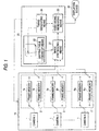
- Fig.1 is a block diagram showing a configuration of a driving aiding system according to an embodiment of the present invention.
- the driving aiding system according to the present embodiment comprises an image picking-up means 10, an image processing portion 20, and a displaying means 30.
- the image picking-up means 10 has N image picking-up means (cameras 1 to N) that are equipped onto the vehicle.
- the image picking-up means 10 has eight cameras in total, i.e., two cameras equipped onto the front portion of the vehicle to monitor the front side of the vehicle, two cameras equipped onto the left side portion of the vehicle to monitor the left side of the vehicle, two cameras equipped onto the right side portion of the vehicle to monitor the right side of the vehicle, and two cameras equipped onto the rear portion of the vehicle to monitor the rear side of the vehicle.
- Each camera is typically a color or monochromatic digital camera having the solid state imaging device such as CCD, CMOS device, etc. Also, each camera may consist of the combination of prism and mirror (not shown) and may be constructed such that the incident light that is passed through the lens, the prism, or the mirror can be transmitted to the imaging device positioned at a remote position.
- vehicle contains the small passenger car, the truck, the bus, etc. and also contains special-purpose vehicles such as the crane vehicle, the shovel loader, etc.
- the image picking-up means 10 further has two frame memories corresponding to the cameras respectively. For instance, an image processing portion 20 reads the information (picked-up image at the preceding capturing timing) stored in the other frame memory Nb in the middle of capturing the picked-up image into one frame memory Na from the camera N.
- the image processing portion 20 comprises an image synthesizing means 21 for receiving the picked-up images of respective cameras and then synthesizing the image, a mapping-table looking-up means 22 provided to process the image synthesis at a high speed, a video signal generating means 23 for converting the image generated by the image synthesizing means 21 into the video signal, a timing generating means 24 for outputting a timing signal to the image picking-up means 10, the mapping-table looking-up means 22, and the video signal generating means 23.
- the image synthesizing means 21 receives the picked-up images from the cameras 1 to N, and then processes these picked-up images.
- the processings herein are i) the image transformation process, and ii) the synthesis process (containing the boundary process) of transformed partial images. These processes I), ii) may be performed separately respectively, otherwise all or a part of these processes may be performed by one step. In the example in Fig.1, the configuration having the mapping table is employed so that the processing of the picked-up image is carried out by one step.
- the mapping table is a table that is provided to execute the process of converting position coordinates of the pixels of the picked-up image into position coordinates of the pixels of the synthesized image at a high speed.
- the position coordinates of the pixels of the picked-up image and the position coordinates of the pixels of the synthesized image may have either a one-to-one correspondence or a plural-to-one correspondence. It depends on portions of the vehicle onto which respective cameras should be equipped, what synthesized image should be generated by respective cameras, etc. that the position coordinates of the pixels of the picked-up image and the position coordinates of the pixels of the synthesized image correspond on a one-to-one basis or correspond on a plural-to-one basis. For instance, if the boundary process is applied at the boundary portions between the picked-up images, the position coordinates of the pixels of the picked-up image and the position coordinates of the pixels of the synthesized image do not always correspond on the one-to-one basis.
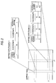
- Fig.2 is a view showing an example of the mapping table.
- the correspondence between the synthesized image and the mapping data is shown based on pixel coordinates (i, j) of the synthesized image.
- the pixel coordinate (i1, j1) is the pixel of the image picked up by the camera 1, and data of the X-coordinate and the Y- coordinate (12, 45) of the picked-up image and data of the necessity degree (1, 0) are prepared in correspondence with the coordinates (mapping data example 1).
- pixel data of the picked-up image at (12, 45) are employed the necessity degree "1", i.e., the pixel data of the picked-up image is copied as it is and then employed.
- the pixel coordinate (i2, j2) is the pixel that corresponds to the overlapping portion between the image picked up by the camera 1 and the image picked up by the camera 2, and the data of the X-coordinate and the Y-coordinate of the images picked-up by the camera 1 and the camera 2 and the data of the necessity degree are prepared (mapping data example 2).
- the synthesized image representing the overall surrounding ground of the vehicle or the synthesized image representing a part of the surrounding ground of the vehicle can be generated at a high speed.
- the synthesized image, the neighboring image, or the synthesized image obtained by arranging both images on one screen, to be described later can be generated at a high speed.
- the mapping table may be prepared in the image synthesizing means 21 or prepared on the outside of the image synthesizing means 21.
- the processor (not shown) in the image synthesizing means 21 looks up any one of the mapping tables for generating the necessary synthesized image, and then generates the synthesized image at a high speed. In this case, it is needless to say that, if the processor can carry out the higher-speed processing, the synthesized image can be generated at a higher speed without the use of the mapping table.
- mapping table is stored in ROM (including writable/erasable ROM such as EEPROM, etc.) or RAM, for example.
- the processor in the above image synthesizing means 21 can write the mapping table onto RAM or ROM by computing the mapping table data, otherwise the mapping table data that are provided as the firmware can be written onto above RAM or ROM by using the data transmitting means such as the communication line, the disk drive, etc., for example.
- the displaying means 30 is typically the liquid crystal display, but other display devices such as the plasma display, etc. may be employed. Also, this displaying means 30 may be commonly used as the vehicle-equipped GPS terminal display (display of the so-called car navigation system), or may be prepared separately from this.
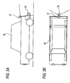
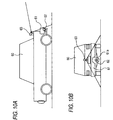
- Figs . 3A and 3B are schematic views showing the situation that the camera is equipped onto the rear portion of the vehicle, wherein Fig. 3A is a side view of the vehicle and Fig. 3B is a top view thereof.
- a hitch 35 for coupling a trailed vehicle such as the trailer, the camping car, etc. is fixed under the center portion of the rear bumper of a trailing vehicle 36.
- a rear-view camera 37 is equipped onto the rear portion of own vehicle 36.
- the camera 37 is fixed to the vehicle 36 such that at least a part of the hitch 35 can enter in the imaging range of the camera 37.
- the rear-view camera 37 is fitted to the rear portion of the vehicle 36, preferably the upper position of the hitch 35.
- This upper position of the hitch 35 signifies the right over the hitch 35 as shown in Fig. 3B, but this position is not always limited to the right over the hitch 35.
- This position may be slightly shifted laterally. In this case, if this position is shifted too much laterally, the horizontal component of the hitch 35 that is looked down at the camera 37 is deviated from the straightly backing direction of the vehicle 36. Therefore, even if the hitch 35 is picked up in the picked-up image of the camera 37, the position alignment between the hitch 35 and the counter coupler becomes difficult. In this meaning, it is desired that the camera 37 should be fitted to the right over the hitch 35 as precise as possible.
- the hitch 35 is caught in the picked-up image of the camera 37, the relative positional relationship between the hitch 35 and the trailed vehicle side coupler can be confirmed by looking at the image. Therefore, there can be achieved such an advantage that the hitch coupling operation can be facilitated.
- Fig.4 is a view showing an example of the synthesized image that is synthesized based on the picked-up image of the rear-view camera 37 by using the above mapping table.
- the synthesized image that is obtained by processing the picked-up image of one rear-view camera 37 while using the mapping table is shown, but the synthesized image shown in Fig. 4 maybe generated by picking up the images of the right and left rear portion of the vehicle separately by means of two rear-view cameras respectively.
- the picked-up image of the rear-view camera 37 is also used as the image to check the safety when the vehicle is backed, the wide-angle camera is used to pick up the image in as wide the range as possible. Therefore, the actual image picked up by the camera 37 is a considerably distorted image and provides the incomprehensible screen if such actual image is displayed on the displaying means 30 as it is.
- a horizontal line 40 is displayed as a real straight line and thus the screen from which the sense of distance is easily comprehensible can be obtained.
- a reference 41a is an image of the trailed vehicle on the coupled destination side, and an image 42a of the destination side coupler is displayed thereon.
- a reference 36a is an image of the trailing vehicle (own vehicle) 36. If the camera 37 is installed such that the rear end portion of own vehicle 36 can be caught in the pick-up range of the camera 37, the picked-up image itself of the camera or the image that is subjected to the coordinate transformation by using the mapping table can be employed as this image 36a. In contrast, if the camera 37 is installed such that the rear end portion of own vehicle 36 cannot be caught (see Fig. 3A), an illustrated image is employed as the image 36a of the rear end portion of own vehicle 36.
- An image 35a of the hitch 35 on the screen is the image obtained by coordinate-transforming the real image by using the mapping table. If a guide line 43 indicating the straight rear side is displayed from this image 35a on the screen, the driver can be guided to know whether or not the destination side coupler is positioned in the hitch backing direction.
- the working process for coupling the hitch 35 to the coupler on the trailed vehicle side is classified roughly into two processes. One is the working process for bringing the hitch 35 close to the destination coupler to some extent, and the other is the working process for fitting exactly the hitch 35 to the destination coupler by the fine steering wheel control after they come close to each other to some extent.
- a wide-range image for displaying a wide range of the rear side of the vehicle to contain the hitch 35 and a neighboring image for displaying merely an extracted partial area to contain the hitch 35 in this wide-range image (the neighboring image is not limited to the neighboring, but a part of the wide-range image may be employed) are generated, and then the wide-range image and the neighboring image are switched to display.
- the screen of the displaying means 30 is divided into two screens, and the wide-range image 50 and the neighboring image 51 are displayed in parallel.
- a reference 70 denotes a guide line indicating a width of own vehicle
- a reference 71 denotes a guide line indicating a width of own vehicle and a distance from own vehicle.
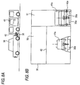
- Figs. 6A, 6B, 7A, 7B, 8A and 8B are views illustrating the transition of the image displayed on the screen of the displaying means 30 along with the progress of respective working processes in the hitch coupling.
- Fig. 6B is a displayed example of the screen in the starting state of the hitch coupling operation (as shown in Fig. 6A, own vehicle 36 is remote from the trailed vehicle 41). In this state, the trailed vehicle 41 is not displayed in the neighboring image 51 on the right side of the synthesized image. Thus, while looking at the wide-range image 50 on the left side of the synthesized image, the driver backs own vehicle 36 to come close to the trailed vehicle 41 until the trailed vehicle 41 can be displayed in the neighboring image 51
- the driver can back own vehicle 36 slowly while checking the rough relative positional relationship between the trailed vehicle 41 and own vehicle 36 by the wide-range image 50 on the left on the screen in the first process of the hitch coupling operation, and then execute the precise positional alignment between them while looking at the neighboring image 51, in which the hitch image 36a and the destination coupler 42a are enlarged, in the next process.
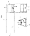
- Fig.9 is a view showing a displayed example of the screen according to another embodiment of the present invention.
- both the wide-range image 50 and the neighboring image 51 are merely displayed in parallel in one screen.
- the relationship between them is clearly shown on the screen.
- an auxiliary line 53 indicating the area of the neighboring image 51 is depicted in the wide-range image 50. That is, the area that is surrounded by a trapezoid (the auxiliary line 53) at the central lower portion of the left wide-range image 50 corresponds to the depicted area of the right neighboring image 51.
- both the wide-range image 50 and the neighboring image 51 maybe displayed in one screen after the screen is divided, like the example in FIG.5.
- the wide-range image 50 and the neighboring image 51 are generated separately such that two images can be shown separately, and then these two images may be switched by the driver's screen switching operation, e.g., the touch operation onto the screen.
- the distance sensor such as the ultrasonic sensor is equipped onto the rear portion of own vehicle, then the wide-range image 50 may be displayed on the screen of the displaying means 30 until a distance to the trailed vehicle reaches a predetermined distance, and then the neighboring image 51 may be displayed on the screen when own vehicle comes closer than the predetermined distance.
- the installing position of the camera onto the vehicle is decided such that at least a part of the hitch can be picked up by the camera.
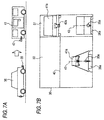
- the cases where the camera cannot be physically equipped onto the vehicle so as to pick up the hitch are not small in number.
- a concave portion 61a is formed in the center lower portion of a rear portion side bumper 61 of a trailing vehicle 60 and then a hitch 62 is fitted to the lower position of the concave portion 61a, the hitch 62 cannot be directly looked at by a rear-view camera 63 equipped onto the rear portion of the vehicle 60.
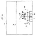
- a guide 62a indicating the position of the hitch (in this example, the illustrated image of the hitch) is displayed by superposing on the synthesized image as shown in Fig.4.
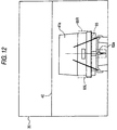
- an alignment guide (guide corresponding to the concave portion 61a of the bumper: a guide line indicated like a near"U" shape by a dotted line around the hitch illustrated image 62a in Fig.11) 64 of the destination coupler and a guide line 65 indicating the top end bumper position of the trailed vehicle, which serves as an aim of the hitch coupling end, are displayed.
- this guide line 65 is shaped into the near"U" shape to both end portions of which guide lines 65L, 65R indicating positions of the widths that are same as the image widths of the trailed vehicle are provided, (the image 42a of) the destination coupler can enter into the inside of the guide line 64 when the image 41a of the trailed vehicle is fitted exactly to a width of this guide line 65. Therefore, the guide line 64 is indispensable and may be provided as the needs may arise.
- the driver While looking at the screen display in Fig.11, i.e., while monitoring the guide 62a indicating the position of the hitch, the driver controls the steering wheel so as to bring the hitch close to the destination coupler and backs own vehicle until the destination coupler is hidden by the bumper of own vehicle, or the like.
- the attention point at this time is to back own vehicle such that lateral positions of the hitch guide (illustrated image of the hitch) 62a and the image 42a of the destination coupler can coincide with each other, i.e, the image 42a of the destination coupler can coincide with the guide line 43 that is extended straightly backward from the hitch position. If both do not coincide with each other, the forward and backward driving of own vehicle is repeated until the both can coincide with each other.
- the care must be taken not to deviate the image 41a of the trailed vehicle from the left and right guides 65L, 65R of the guide line 65 when the image 42a of the destination coupler is hidden by the own vehicle image 60a.
- the positional alignment between the hitch and the coupler on the trailed vehicle side can be carried out with good precision.
- the wide-range image and the neighboring image described in the preceding embodiment can be switched to display or can be displayed in parallel in one screen.
- the neighboring image is explained, but the image picking up the neighboring area should not always be employed.
- the image portion of the destination coupler is extracted to display, such image portion is effective in the positional alignment of the hitch.
- the enlarged image is not always employed as the neighboring image, and the deformed image to which the coordinate transformation is applied to arrange the viewpoint over the vehicle may be employed.
- the camera is equipped such that at least a part of the hitch can be displayed in the picked-up image of the camera. Therefore, the relative positional relationship between the hitch and the destination coupler can be easily grasped by the picked-up image of the camera and thus the coupling operation can be carried out with good precision.
Landscapes
- Engineering & Computer Science (AREA)
- Transportation (AREA)
- Mechanical Engineering (AREA)
- Chemical & Material Sciences (AREA)
- Combustion & Propulsion (AREA)
- Physics & Mathematics (AREA)
- General Physics & Mathematics (AREA)
- Closed-Circuit Television Systems (AREA)
- Image Processing (AREA)
- Image Analysis (AREA)
- Fittings On The Vehicle Exterior For Carrying Loads, And Devices For Holding Or Mounting Articles (AREA)
Abstract
Description
Claims (6)
- A driving aiding system comprising:a displaying means arranged at a position that can be looked at from a driver's seat of a vehicle;an image picking-up means for picking up an image of a rearward direction of the vehicle containing at least a part of a hitch that is provided to a rear portion of the vehicle; andan image processing means for causing the displaying means to display a synthesized image that is obtained by image-processing an image picked up by the image picking-up means.
- A driving aiding system according to claim 1, wherein the image processing means has a means for switching the synthesized image and an extracted image that is obtained by cutting out a predetermined area of the synthesized image to enlarge or deform and displaying it on the displaying means.
- A driving aiding system according to claim 1, wherein the image processing means has a means for displaying the synthesized image and an extracted image that is obtained by cutting out a predetermined area of the synthesized image to enlarge or deform in parallel on one screen of the displaying means.
- A driving aiding system according to claim 2 or claim 3, wherein the image processing means has a means for displaying a guide line indicating a display area of the extracted image in the synthesized image.
- A driving aiding system comprising:a displaying means arranged at a position that can be looked at from a driver's seat of a vehicle;an image picking-up means for picking up an image of a rearward direction of the vehicle; andan image processing means for superposing an illustrated image of a hitch indicating a presence position of the hitch equipped to a rear portion of the vehicle onto a synthesized image to display when the synthesized image that is obtained by image-processing an image picked up by the image picking-up means is displayed on the displaying means.
- A driving aiding system according to claim 5, wherein the image processing means has a means for displaying a guide line for guiding a position of a trailed vehicle side coupler to be coupled to the hitch on a screen of the displaying means.
Applications Claiming Priority (2)
| Application Number | Priority Date | Filing Date | Title |
|---|---|---|---|
| JP2001110257 | 2001-04-09 | ||
| JP2001110257A JP3483143B2 (en) | 2001-04-09 | 2001-04-09 | Driving support device |
Publications (3)
| Publication Number | Publication Date |
|---|---|
| EP1251025A2 true EP1251025A2 (en) | 2002-10-23 |
| EP1251025A3 EP1251025A3 (en) | 2005-12-07 |
| EP1251025B1 EP1251025B1 (en) | 2008-01-09 |
Family
ID=18962066
Family Applications (1)
| Application Number | Title | Priority Date | Filing Date |
|---|---|---|---|
| EP02007712A Expired - Lifetime EP1251025B1 (en) | 2001-04-09 | 2002-04-05 | Driving aiding system |
Country Status (4)
| Country | Link |
|---|---|
| US (1) | US7006127B2 (en) |
| EP (1) | EP1251025B1 (en) |
| JP (1) | JP3483143B2 (en) |
| DE (1) | DE60224473T2 (en) |
Cited By (7)
| Publication number | Priority date | Publication date | Assignee | Title |
|---|---|---|---|---|
| EP1434441A4 (en) * | 2001-09-28 | 2004-11-10 | Matsushita Electric Industrial Co Ltd | DRIVING SUPPORT DISPLAY DEVICE |
| CN1878299B (en) * | 2005-06-07 | 2010-06-23 | 日产自动车株式会社 | Image display apparatus and method |
| GB2469438A (en) * | 2009-03-09 | 2010-10-20 | Applic Solutions | Displaying movement of an object |
| EP2620326A1 (en) * | 2012-01-24 | 2013-07-31 | Robert Bosch Gmbh | Method and device for supporting a coupling procedure of a trailer |
| CN104159757A (en) * | 2012-02-29 | 2014-11-19 | 罗伯特·博世有限公司 | Hitch alignment assistance |
| CN104554006A (en) * | 2013-10-24 | 2015-04-29 | 通用汽车环球科技运作有限责任公司 | Smart tow |
| DE102006049541B4 (en) * | 2006-10-20 | 2018-10-31 | Volkswagen Ag | Method and device for determining a trailer support load |
Families Citing this family (90)
| Publication number | Priority date | Publication date | Assignee | Title |
|---|---|---|---|---|
| US7375728B2 (en) * | 2001-10-01 | 2008-05-20 | University Of Minnesota | Virtual mirror |
| JP4739569B2 (en) * | 2001-04-09 | 2011-08-03 | パナソニック株式会社 | Driving assistance device |
| US20060061008A1 (en) | 2004-09-14 | 2006-03-23 | Lee Karner | Mounting assembly for vehicle interior mirror |
| JP2004212658A (en) * | 2002-12-27 | 2004-07-29 | Sumitomo Electric Ind Ltd | Image display system, image display method, and image processing device |
| DE102004008928A1 (en) * | 2004-02-24 | 2005-09-08 | Bayerische Motoren Werke Ag | Method for coupling a trailer using a vehicle level control |
| US20050206231A1 (en) * | 2004-03-18 | 2005-09-22 | Ford Global Technologies, Llc | Method and apparatus for controlling an automotive vehicle using brake-steer and normal load adjustment |
| US7165644B2 (en) | 2004-03-18 | 2007-01-23 | Ford Global Technologies, Llc | Method and apparatus of controlling an automotive vehicle using brake-steer as a function of steering wheel torque |
| US20050206225A1 (en) * | 2004-03-18 | 2005-09-22 | Ford Global Technologies, Llc | Method and apparatus for predicting the position of a trailer relative to a vehicle |
| US7950751B2 (en) * | 2004-03-18 | 2011-05-31 | Ford Global Technologies | Method and apparatus for maintaining a trailer in a straight position relative to the vehicle |
| US8380416B2 (en) * | 2004-03-18 | 2013-02-19 | Ford Global Technologies | Method and apparatus for controlling brake-steer in an automotive vehicle in reverse |
| DE102004029130A1 (en) * | 2004-06-17 | 2005-12-29 | Daimlerchrysler Ag | Method for coupling a trailer to a motor vehicle |
| JP4956915B2 (en) * | 2005-05-20 | 2012-06-20 | 日産自動車株式会社 | Video display device and video display method |
| DE102005031365B4 (en) * | 2005-06-30 | 2008-04-30 | Jost-Werke Gmbh | Device for detecting and displaying the position of components of vehicle clutches |
| JP4679293B2 (en) * | 2005-08-08 | 2011-04-27 | 三洋電機株式会社 | In-vehicle panoramic camera system |
| JP2007108159A (en) * | 2005-09-15 | 2007-04-26 | Auto Network Gijutsu Kenkyusho:Kk | Driving assistance device |
| FR2891934B1 (en) * | 2005-10-12 | 2008-01-18 | Valeo Electronique Sys Liaison | DEVICE FOR PROCESSING VIDEO DATA FOR A MOTOR VEHICLE |
| DE102005055350A1 (en) * | 2005-11-21 | 2007-05-24 | Robert Bosch Gmbh | Method for controlling the visual field size of a video system and video system for a motor vehicle |
| US8194132B2 (en) | 2006-01-20 | 2012-06-05 | Old World Industries, Llc | System for monitoring an area adjacent a vehicle |
| US8698894B2 (en) | 2006-02-07 | 2014-04-15 | Magna Electronics Inc. | Camera mounted at rear of vehicle |
| JP4104631B2 (en) | 2006-03-27 | 2008-06-18 | 三洋電機株式会社 | Driving support device |
| US20070233361A1 (en) * | 2006-03-30 | 2007-10-04 | Ford Global Technologies, Llc | Centralized Image Processing For An Automobile With A Navigation System |
| JP4257356B2 (en) * | 2006-09-26 | 2009-04-22 | 株式会社日立製作所 | Image generating apparatus and image generating method |
| JP4853712B2 (en) * | 2006-12-28 | 2012-01-11 | アイシン精機株式会社 | Parking assistance device |
| US8888120B2 (en) * | 2007-01-25 | 2014-11-18 | Target Hitch Llc | Towing vehicle guidance for trailer hitch connection |
| US8888121B2 (en) * | 2007-01-25 | 2014-11-18 | Target Hitch Llc | Towing vehicle guidance for trailer hitch connection |
| JP4286294B2 (en) * | 2007-02-21 | 2009-06-24 | 三洋電機株式会社 | Driving support system |
| GB2447672B (en) | 2007-03-21 | 2011-12-14 | Ford Global Tech Llc | Vehicle manoeuvring aids |
| US20090002487A1 (en) * | 2007-06-26 | 2009-01-01 | Martin Poulin | Portable Vehicle Mounted Monitoring System |
| US8451107B2 (en) | 2007-09-11 | 2013-05-28 | Magna Electronics, Inc. | Imaging system for vehicle |
| US7777615B2 (en) | 2008-03-20 | 2010-08-17 | Toyota Motor Engineering & Manufacturing North America, Inc. | System for assisting the attachment of a trailer to a vehicle |
| US20090271078A1 (en) * | 2008-04-29 | 2009-10-29 | Mike Dickinson | System and method for identifying a trailer being towed by a vehicle |
| TWI334393B (en) * | 2008-10-07 | 2010-12-11 | Ind Tech Res Inst | Image-based vehicle maneuvering assistant method and system |
| CN101727756B (en) * | 2008-10-16 | 2012-07-25 | 财团法人工业技术研究院 | Method and system for moving image-assisted guidance of vehicles |
| JP5116657B2 (en) * | 2008-12-25 | 2013-01-09 | 本田技研工業株式会社 | Towed object connection detection device |
| US8138899B2 (en) * | 2009-07-01 | 2012-03-20 | Ford Global Technologies, Llc | Rear camera backup assistance with touchscreen display using two points of interest |
| DE102009045284A1 (en) * | 2009-10-02 | 2011-04-07 | Robert Bosch Gmbh | Method for supporting driver during driving of manoeuvre for coupling e.g. camping trailer, with coupling point at towing device of motor vehicle, involves representing distance and direction between point and towing device for driver |
| US20110153266A1 (en) * | 2009-12-23 | 2011-06-23 | Regents Of The University Of Minnesota | Augmented vehicle location system |
| US9264672B2 (en) | 2010-12-22 | 2016-02-16 | Magna Mirrors Of America, Inc. | Vision display system for vehicle |
| US9085261B2 (en) * | 2011-01-26 | 2015-07-21 | Magna Electronics Inc. | Rear vision system with trailer angle detection |
| JPWO2012117693A1 (en) | 2011-03-02 | 2014-07-07 | パナソニック株式会社 | Driving support device and towing vehicle |
| US9854209B2 (en) | 2011-04-19 | 2017-12-26 | Ford Global Technologies, Llc | Display system utilizing vehicle and trailer dynamics |
| US9723274B2 (en) | 2011-04-19 | 2017-08-01 | Ford Global Technologies, Llc | System and method for adjusting an image capture setting |
| US10196088B2 (en) | 2011-04-19 | 2019-02-05 | Ford Global Technologies, Llc | Target monitoring system and method |
| US9926008B2 (en) | 2011-04-19 | 2018-03-27 | Ford Global Technologies, Llc | Trailer backup assist system with waypoint selection |
| US8976246B1 (en) * | 2012-04-03 | 2015-03-10 | Michael E. Rappuhn | Gooseneck or fifth wheel trailer hitch alignment and safety system |
| US9558409B2 (en) | 2012-09-26 | 2017-01-31 | Magna Electronics Inc. | Vehicle vision system with trailer angle detection |
| US9446713B2 (en) | 2012-09-26 | 2016-09-20 | Magna Electronics Inc. | Trailer angle detection system |
| US10755110B2 (en) | 2013-06-28 | 2020-08-25 | Magna Electronics Inc. | Trailering assist system for vehicle |
| CN105898189A (en) * | 2014-05-06 | 2016-08-24 | 无锡威莱斯电子有限公司 | Wireless reversing image system with adjustable reversing auxiliary lines |
| US9963004B2 (en) | 2014-07-28 | 2018-05-08 | Ford Global Technologies, Llc | Trailer sway warning system and method |
| US9804022B2 (en) | 2015-03-24 | 2017-10-31 | Ford Global Technologies, Llc | System and method for hitch angle detection |
| US10384607B2 (en) | 2015-10-19 | 2019-08-20 | Ford Global Technologies, Llc | Trailer backup assist system with hitch angle offset estimation |
| US10611407B2 (en) | 2015-10-19 | 2020-04-07 | Ford Global Technologies, Llc | Speed control for motor vehicles |
| JP6701045B2 (en) * | 2015-10-22 | 2020-05-27 | 新明和工業株式会社 | Container handling vehicle |
| JP6716411B2 (en) * | 2015-10-22 | 2020-07-01 | 新明和工業株式会社 | Container handling vehicle |
| US9836060B2 (en) | 2015-10-28 | 2017-12-05 | Ford Global Technologies, Llc | Trailer backup assist system with target management |
| US10017115B2 (en) | 2015-11-11 | 2018-07-10 | Ford Global Technologies, Llc | Trailer monitoring system and method |
| US9731568B2 (en) * | 2015-12-01 | 2017-08-15 | GM Global Technology Operations LLC | Guided tow hitch control system and method |
| US10011228B2 (en) | 2015-12-17 | 2018-07-03 | Ford Global Technologies, Llc | Hitch angle detection for trailer backup assist system using multiple imaging devices |
| US10155478B2 (en) | 2015-12-17 | 2018-12-18 | Ford Global Technologies, Llc | Centerline method for trailer hitch angle detection |
| US9796228B2 (en) | 2015-12-17 | 2017-10-24 | Ford Global Technologies, Llc | Hitch angle detection for trailer backup assist system |
| US9798953B2 (en) | 2015-12-17 | 2017-10-24 | Ford Global Technologies, Llc | Template matching solution for locating trailer hitch point |
| US9827818B2 (en) | 2015-12-17 | 2017-11-28 | Ford Global Technologies, Llc | Multi-stage solution for trailer hitch angle initialization |
| US9934572B2 (en) | 2015-12-17 | 2018-04-03 | Ford Global Technologies, Llc | Drawbar scan solution for locating trailer hitch point |
| US9610975B1 (en) * | 2015-12-17 | 2017-04-04 | Ford Global Technologies, Llc | Hitch angle detection for trailer backup assist system |
| US10005492B2 (en) | 2016-02-18 | 2018-06-26 | Ford Global Technologies, Llc | Trailer length and hitch angle bias estimation |
| US10106193B2 (en) | 2016-07-01 | 2018-10-23 | Ford Global Technologies, Llc | Enhanced yaw rate trailer angle detection initialization |
| DE102017211395B4 (en) | 2016-08-05 | 2024-03-14 | Volkswagen Aktiengesellschaft | Method for supporting a coupling process and support system |
| US10046800B2 (en) | 2016-08-10 | 2018-08-14 | Ford Global Technologies, Llc | Trailer wheel targetless trailer angle detection |
| US10222804B2 (en) | 2016-10-21 | 2019-03-05 | Ford Global Technologies, Llc | Inertial reference for TBA speed limiting |
| JP6729409B2 (en) | 2017-01-16 | 2020-07-22 | アイシン精機株式会社 | Perimeter monitoring device |
| EP3379222B1 (en) | 2017-03-22 | 2020-12-30 | Methode Electronics Malta Ltd. | Magnetoelastic based sensor assembly |
| US10332002B2 (en) * | 2017-03-27 | 2019-06-25 | GM Global Technology Operations LLC | Method and apparatus for providing trailer information |
| US10710585B2 (en) | 2017-09-01 | 2020-07-14 | Ford Global Technologies, Llc | Trailer backup assist system with predictive hitch angle functionality |
| PL3495202T3 (en) * | 2017-12-05 | 2021-02-08 | Guima Palfinger S.A.S. | Truck-mountable detection system |
| US11491832B2 (en) | 2018-02-27 | 2022-11-08 | Methode Electronics, Inc. | Towing systems and methods using magnetic field sensing |
| US11014417B2 (en) | 2018-02-27 | 2021-05-25 | Methode Electronics, Inc. | Towing systems and methods using magnetic field sensing |
| US11084342B2 (en) | 2018-02-27 | 2021-08-10 | Methode Electronics, Inc. | Towing systems and methods using magnetic field sensing |
| US11221262B2 (en) | 2018-02-27 | 2022-01-11 | Methode Electronics, Inc. | Towing systems and methods using magnetic field sensing |
| US10670479B2 (en) | 2018-02-27 | 2020-06-02 | Methode Electronics, Inc. | Towing systems and methods using magnetic field sensing |
| US11135882B2 (en) | 2018-02-27 | 2021-10-05 | Methode Electronics, Inc. | Towing systems and methods using magnetic field sensing |
| US10351061B1 (en) * | 2018-03-09 | 2019-07-16 | Deere & Company | Implement attachment guidance system |
| US11050933B2 (en) * | 2018-04-27 | 2021-06-29 | Continenal Automotive Systems, Inc. | Device and method for determining a center of a trailer tow coupler |
| US11077795B2 (en) | 2018-11-26 | 2021-08-03 | Ford Global Technologies, Llc | Trailer angle detection using end-to-end learning |
| US20200238912A1 (en) * | 2019-01-30 | 2020-07-30 | AISIN Technical Center of America, Inc. | Backup camera system for a vehicle having a trailer hitch |
| US10829046B2 (en) | 2019-03-06 | 2020-11-10 | Ford Global Technologies, Llc | Trailer angle detection using end-to-end learning |
| US20210206329A1 (en) * | 2020-01-06 | 2021-07-08 | Gentex Corporation | Full display mirror system with ruggedized portable imager |
| US12286156B2 (en) * | 2020-05-08 | 2025-04-29 | Ford Global Technologies, Llc | Trailer GPS location storage and recall for hitch assist operation |
| JP2024141497A (en) | 2023-03-29 | 2024-10-10 | 株式会社アイシン | Driving Support Devices |
| JP2025174341A (en) * | 2024-05-17 | 2025-11-28 | 株式会社小糸製作所 | Vehicle lighting fixtures |
Family Cites Families (12)
| Publication number | Priority date | Publication date | Assignee | Title |
|---|---|---|---|---|
| JPH03295759A (en) | 1990-04-12 | 1991-12-26 | Hitachi Ltd | Monitoring device |
| US5112172A (en) * | 1990-09-12 | 1992-05-12 | Knorr Brake Holding Corporation | Sliding pull up stanchion and method |
| DE4135795A1 (en) | 1991-10-30 | 1993-05-06 | Rockinger Spezialfabrik Fuer Anhaengerkupplungen Gmbh & Co, 8000 Muenchen, De | SEMITRAIL KEYWORD: MULTICOUPLING FOR SEMI-TRAILER |
| JP3214022B2 (en) | 1992-01-31 | 2001-10-02 | 株式会社島津製作所 | Display for vehicle connection work |
| US5650764A (en) | 1994-08-25 | 1997-07-22 | Mccullough; Deborah Y. | Trailer alignment device with visual display |
| DE69736967T2 (en) * | 1996-06-19 | 2007-07-26 | Matsushita Electric Industrial Co., Ltd., Kadoma | Device for obtaining road network zone data from the block data of a road network map, system for transforming this data and display of a transformed map and geographical information system |
| JP3575279B2 (en) | 1998-05-22 | 2004-10-13 | アイシン精機株式会社 | Parking assistance device |
| JP3183284B2 (en) | 1999-01-19 | 2001-07-09 | 株式会社豊田自動織機製作所 | Steering support device for reversing a vehicle |
| US7366595B1 (en) | 1999-06-25 | 2008-04-29 | Seiko Epson Corporation | Vehicle drive assist system |
| US6611744B1 (en) * | 1999-08-12 | 2003-08-26 | Kabushiki Kaisha Toyoda Jidoshokki Seisakusho | Steering assist apparatus for traveling in reverse |
| JP3645196B2 (en) * | 2001-02-09 | 2005-05-11 | 松下電器産業株式会社 | Image synthesizer |
| JP2002359839A (en) * | 2001-03-29 | 2002-12-13 | Matsushita Electric Ind Co Ltd | Rear view camera image display method and device |
-
2001
- 2001-04-09 JP JP2001110257A patent/JP3483143B2/en not_active Expired - Lifetime
-
2002
- 2002-04-04 US US10/116,205 patent/US7006127B2/en not_active Expired - Lifetime
- 2002-04-05 EP EP02007712A patent/EP1251025B1/en not_active Expired - Lifetime
- 2002-04-05 DE DE60224473T patent/DE60224473T2/en not_active Expired - Lifetime
Cited By (11)
| Publication number | Priority date | Publication date | Assignee | Title |
|---|---|---|---|---|
| EP1434441A4 (en) * | 2001-09-28 | 2004-11-10 | Matsushita Electric Industrial Co Ltd | DRIVING SUPPORT DISPLAY DEVICE |
| US7256688B2 (en) | 2001-09-28 | 2007-08-14 | Matsushita Electric Industrial Co., Ltd. | Drive support display apparatus |
| CN1878299B (en) * | 2005-06-07 | 2010-06-23 | 日产自动车株式会社 | Image display apparatus and method |
| DE102006049541B4 (en) * | 2006-10-20 | 2018-10-31 | Volkswagen Ag | Method and device for determining a trailer support load |
| GB2469438A (en) * | 2009-03-09 | 2010-10-20 | Applic Solutions | Displaying movement of an object |
| GB2469438B (en) * | 2009-03-09 | 2014-04-09 | Applic Solutions Electronics & Vision Ltd | Display movement of an object |
| EP2620326A1 (en) * | 2012-01-24 | 2013-07-31 | Robert Bosch Gmbh | Method and device for supporting a coupling procedure of a trailer |
| EP2620326B1 (en) | 2012-01-24 | 2015-04-01 | Robert Bosch Gmbh | Method and device for supporting a coupling procedure of a trailer |
| CN104159757A (en) * | 2012-02-29 | 2014-11-19 | 罗伯特·博世有限公司 | Hitch alignment assistance |
| EP2819858B1 (en) * | 2012-02-29 | 2019-10-30 | Robert Bosch GmbH | Hitch alignment assistance |
| CN104554006A (en) * | 2013-10-24 | 2015-04-29 | 通用汽车环球科技运作有限责任公司 | Smart tow |
Also Published As
| Publication number | Publication date |
|---|---|
| JP3483143B2 (en) | 2004-01-06 |
| US20020145663A1 (en) | 2002-10-10 |
| JP2002312768A (en) | 2002-10-25 |
| DE60224473D1 (en) | 2008-02-21 |
| DE60224473T2 (en) | 2009-01-08 |
| US7006127B2 (en) | 2006-02-28 |
| EP1251025A3 (en) | 2005-12-07 |
| EP1251025B1 (en) | 2008-01-09 |
Similar Documents
| Publication | Publication Date | Title |
|---|---|---|
| US7006127B2 (en) | Driving aiding system | |
| EP1249365B1 (en) | Driving aiding system | |
| JP3652678B2 (en) | Vehicle surrounding monitoring apparatus and adjustment method thereof | |
| JP4766841B2 (en) | Camera device and vehicle periphery monitoring device mounted on vehicle | |
| CN100536564C (en) | Vehicle surroundings monitoring system and method thereof | |
| US8009868B2 (en) | Method of processing images photographed by plural cameras and apparatus for the same | |
| JP4512293B2 (en) | Monitoring system and monitoring method | |
| US20190313049A1 (en) | Display system and method | |
| JP3372944B2 (en) | Monitoring system | |
| US20090102921A1 (en) | Vehicle-mounted image capturing apparatus | |
| US20070058273A1 (en) | Driving assist system | |
| EP1288618A2 (en) | Driving assistance display apparatus | |
| US8477191B2 (en) | On-vehicle image pickup apparatus | |
| WO2002007443A1 (en) | Monitoring system | |
| US11273763B2 (en) | Image processing apparatus, image processing method, and image processing program | |
| JP3753681B2 (en) | Monitoring system | |
| WO2011001794A1 (en) | Image generation device and image display system | |
| JP2011193485A (en) | Camera device mounted on vehicle, and apparatus for monitoring vehicle periphery | |
| JP7766057B2 (en) | Driving assistance devices | |
| JP2003104145A (en) | Driving support display device | |
| JP5718080B2 (en) | Vehicle periphery monitoring device | |
| JP4499319B2 (en) | Driving support device, driving support method, and driving guide data creation method | |
| JP2006254318A (en) | In-vehicle camera, in-vehicle monitoring device, and front road area imaging method | |
| JP2021512536A (en) | How and equipment to drive a camera / monitor system for a car | |
| JP2006224927A (en) | Vehicle periphery visual recognition device |
Legal Events
| Date | Code | Title | Description |
|---|---|---|---|
| PUAI | Public reference made under article 153(3) epc to a published international application that has entered the european phase |
Free format text: ORIGINAL CODE: 0009012 |
|
| AK | Designated contracting states |
Kind code of ref document: A2 Designated state(s): AT BE CH CY DE DK ES FI FR GB GR IE IT LI LU MC NL PT SE TR |
|
| AX | Request for extension of the european patent |
Free format text: AL;LT;LV;MK;RO;SI |
|
| PUAL | Search report despatched |
Free format text: ORIGINAL CODE: 0009013 |
|
| AK | Designated contracting states |
Kind code of ref document: A3 Designated state(s): AT BE CH CY DE DK ES FI FR GB GR IE IT LI LU MC NL PT SE TR |
|
| AX | Request for extension of the european patent |
Extension state: AL LT LV MK RO SI |
|
| RIC1 | Information provided on ipc code assigned before grant |
Ipc: 7B 60D 1/36 B Ipc: 7B 60K 37/02 A |
|
| 17P | Request for examination filed |
Effective date: 20060208 |
|
| AKX | Designation fees paid |
Designated state(s): DE FR GB IT |
|
| 17Q | First examination report despatched |
Effective date: 20060529 |
|
| GRAP | Despatch of communication of intention to grant a patent |
Free format text: ORIGINAL CODE: EPIDOSNIGR1 |
|
| GRAS | Grant fee paid |
Free format text: ORIGINAL CODE: EPIDOSNIGR3 |
|
| GRAA | (expected) grant |
Free format text: ORIGINAL CODE: 0009210 |
|
| AK | Designated contracting states |
Kind code of ref document: B1 Designated state(s): DE FR GB IT |
|
| REG | Reference to a national code |
Ref country code: GB Ref legal event code: FG4D |
|
| REF | Corresponds to: |
Ref document number: 60224473 Country of ref document: DE Date of ref document: 20080221 Kind code of ref document: P |
|
| ET | Fr: translation filed | ||
| PLBE | No opposition filed within time limit |
Free format text: ORIGINAL CODE: 0009261 |
|
| STAA | Information on the status of an ep patent application or granted ep patent |
Free format text: STATUS: NO OPPOSITION FILED WITHIN TIME LIMIT |
|
| RAP2 | Party data changed (patent owner data changed or rights of a patent transferred) |
Owner name: PANASONIC CORPORATION |
|
| 26N | No opposition filed |
Effective date: 20081010 |
|
| REG | Reference to a national code |
Ref country code: FR Ref legal event code: PLFP Year of fee payment: 15 |
|
| REG | Reference to a national code |
Ref country code: FR Ref legal event code: PLFP Year of fee payment: 16 |
|
| REG | Reference to a national code |
Ref country code: FR Ref legal event code: PLFP Year of fee payment: 17 |
|
| REG | Reference to a national code |
Ref country code: DE Ref legal event code: R084 Ref document number: 60224473 Country of ref document: DE |
|
| REG | Reference to a national code |
Ref country code: DE Ref legal event code: R085 Ref document number: 60224473 Country of ref document: DE |
|
| PGFP | Annual fee paid to national office [announced via postgrant information from national office to epo] |
Ref country code: FR Payment date: 20210309 Year of fee payment: 20 Ref country code: IT Payment date: 20210310 Year of fee payment: 20 |
|
| PGFP | Annual fee paid to national office [announced via postgrant information from national office to epo] |
Ref country code: GB Payment date: 20210318 Year of fee payment: 20 |
|
| PGFP | Annual fee paid to national office [announced via postgrant information from national office to epo] |
Ref country code: DE Payment date: 20210316 Year of fee payment: 20 |
|
| REG | Reference to a national code |
Ref country code: DE Ref legal event code: R071 Ref document number: 60224473 Country of ref document: DE |
|
| REG | Reference to a national code |
Ref country code: GB Ref legal event code: PE20 Expiry date: 20220404 |
|
| PG25 | Lapsed in a contracting state [announced via postgrant information from national office to epo] |
Ref country code: GB Free format text: LAPSE BECAUSE OF EXPIRATION OF PROTECTION Effective date: 20220404 |