EP1251327A2 - Three-dimensional shape measuring method - Google Patents
Three-dimensional shape measuring method Download PDFInfo
- Publication number
- EP1251327A2 EP1251327A2 EP01128130A EP01128130A EP1251327A2 EP 1251327 A2 EP1251327 A2 EP 1251327A2 EP 01128130 A EP01128130 A EP 01128130A EP 01128130 A EP01128130 A EP 01128130A EP 1251327 A2 EP1251327 A2 EP 1251327A2
- Authority
- EP
- European Patent Office
- Prior art keywords
- dimensional
- grid
- measured
- obtaining
- dimensional shape
- Prior art date
- Legal status (The legal status is an assumption and is not a legal conclusion. Google has not performed a legal analysis and makes no representation as to the accuracy of the status listed.)
- Withdrawn
Links
Images




Classifications
-
- G—PHYSICS
- G01—MEASURING; TESTING
- G01B—MEASURING LENGTH, THICKNESS OR SIMILAR LINEAR DIMENSIONS; MEASURING ANGLES; MEASURING AREAS; MEASURING IRREGULARITIES OF SURFACES OR CONTOURS
- G01B11/00—Measuring arrangements characterised by the use of optical techniques
- G01B11/24—Measuring arrangements characterised by the use of optical techniques for measuring contours or curvatures
-
- G—PHYSICS
- G01—MEASURING; TESTING
- G01B—MEASURING LENGTH, THICKNESS OR SIMILAR LINEAR DIMENSIONS; MEASURING ANGLES; MEASURING AREAS; MEASURING IRREGULARITIES OF SURFACES OR CONTOURS
- G01B11/00—Measuring arrangements characterised by the use of optical techniques
- G01B11/24—Measuring arrangements characterised by the use of optical techniques for measuring contours or curvatures
- G01B11/25—Measuring arrangements characterised by the use of optical techniques for measuring contours or curvatures by projecting a pattern, e.g. one or more lines, moiré fringes on the object
- G01B11/2509—Color coding
-
- G—PHYSICS
- G01—MEASURING; TESTING
- G01B—MEASURING LENGTH, THICKNESS OR SIMILAR LINEAR DIMENSIONS; MEASURING ANGLES; MEASURING AREAS; MEASURING IRREGULARITIES OF SURFACES OR CONTOURS
- G01B11/00—Measuring arrangements characterised by the use of optical techniques
- G01B11/24—Measuring arrangements characterised by the use of optical techniques for measuring contours or curvatures
- G01B11/25—Measuring arrangements characterised by the use of optical techniques for measuring contours or curvatures by projecting a pattern, e.g. one or more lines, moiré fringes on the object
- G01B11/2513—Measuring arrangements characterised by the use of optical techniques for measuring contours or curvatures by projecting a pattern, e.g. one or more lines, moiré fringes on the object with several lines being projected in more than one direction, e.g. grids, patterns
-
- G—PHYSICS
- G01—MEASURING; TESTING
- G01B—MEASURING LENGTH, THICKNESS OR SIMILAR LINEAR DIMENSIONS; MEASURING ANGLES; MEASURING AREAS; MEASURING IRREGULARITIES OF SURFACES OR CONTOURS
- G01B11/00—Measuring arrangements characterised by the use of optical techniques
- G01B11/24—Measuring arrangements characterised by the use of optical techniques for measuring contours or curvatures
- G01B11/25—Measuring arrangements characterised by the use of optical techniques for measuring contours or curvatures by projecting a pattern, e.g. one or more lines, moiré fringes on the object
- G01B11/2536—Measuring arrangements characterised by the use of optical techniques for measuring contours or curvatures by projecting a pattern, e.g. one or more lines, moiré fringes on the object using several gratings with variable grating pitch, projected on the object with the same angle of incidence
-
- G—PHYSICS
- G06—COMPUTING OR CALCULATING; COUNTING
- G06T—IMAGE DATA PROCESSING OR GENERATION, IN GENERAL
- G06T7/00—Image analysis
- G06T7/50—Depth or shape recovery
- G06T7/521—Depth or shape recovery from laser ranging, e.g. using interferometry; from the projection of structured light
Definitions
- the present invention relates to a three-dimensional shape measuring method, more particularly, to a method of measuring an object having a three-dimensional shape, by projecting grid patterns upon the object and using a projection image thereof.
- Unexamined Japanese Patent Publication No. 10-246612 discloses a method comprising the steps of: projecting upon the object to be measured a two-dimensional grid pattern formed by superimposing a plurality of one-dimensional grids each having a period and direction different from those of the others; imaging a two-dimensional grid image deformed in accordance with the three-dimensional shape of the object to be measured; detecting a phase for each of the one-dimensional grid components from the two-dimensional grid image; and obtaining the measurement value of the three-dimensional shape of the object to be measured on the basis of the detected phases.
- the present invention was made to solve the aforementioned problem. More particularly, the object of the present invention is to provide a method of measuring the shape of an object having three-dimensions, with improved precision.
- a method for obtaining a measurement value of a three-dimensional shape of an object using a grid image formed by projecting a plurality of grid patterns upon the object to be measured, the method comprising the steps of: projecting the grid patterns upon the object to be measured, the grid patterns comprising a plurality of one-dimensional grids of different colors, each having a distinctive period and direction; imaging the grid patterns deformed in accordance with the three-dimensional shape of the object to be measured; separating from the grid image each of the one-dimensional grids of different colors; detecting a phase for each of the one-dimensional grids; and obtaining the measurement value on the basis of the detected phases.
- the one-dimensional grids of different colors may be red, green and blue. Also, it is preferable that a straight line connecting the center of a projection lens, which projects light sources in the form of grid patterns, with the center of an image formation lens, which senses the image of the grid patterns, is parallel to a reference surface on which the object to be measured is placed. Furthermore, the method may further comprise a step of measuring color information of the object to be measured by imaging the object to be measured by use of white light.
- a one-dimensional grid 1 as used in this embodiment is red.
- the one-dimensional grid 1 is composed of red lines periodically repeated (with period d1) and extending in the vertical direction.
- a one-dimensional grid 2 as used in this embodiment is green.
- the one-dimensional grid 2 is composed of green lines periodically repeated (with period d2) and extending in an oblique direction.
- a one-dimensional grid 3 as used in this embodiment is blue.
- the one-dimensional grid 3 is composed of blue lines periodically repeated (with period d3) and extending in an oblique direction of which an oblique angle is greater than that of the green lines.
- the one-dimensional grids 1, 2 and 3 may be composed of dots, instead of lines. Also, for the one-dimensional grids 1, 2 and 3, sinusoidal grids are ideally used, which contain no unnecessary harmonic components. However, it is also possible to use rectangular grids that can be made more easily, by removing such unnecessary harmonic components at the stage of signal processing.
- the ratio of d1 to d2 to d3 is preferably set to be 3 to 5 to 7, or any other ratio represented by prime numbers.
- the one-dimensional grids 1, 2 and 3 are illuminated, via lenses 10, 11 and 12, respectively, with their respective white light sources 4a, 4b and 4c.
- the red grid of one dimension 1 is disposed coaxially relative to an optical axis of the projection lens 5.
- the red grid of one dimension 1 is illuminated by the white light source 4a, such that an image thereof is projected, by the projection lens 5, upon a reference surface 8.
- the green grid of one dimension 2 is disposed in parallel with the optical axis of the projection lens 5.
- the green grid of one dimension 2 is illuminated by the white light source 4b, such that an image thereof is projected, via a prism mechanism 16, by the projection lens 5, upon the reference surface 8.
- the blue grid of one dimension 3 is disposed in such a manner that it is opposed to the green grid of one dimension 2, with the optical axis intervening therebetween.
- the blue grid of one dimension 3 is illuminated by the white light source 4c, such that an image thereof is projected, via the prism mechanism 16, by the projection lens 5, upon the reference surface 8.
- three objects to be measured 6a, 6b and 7 are individually composed of isolated faces having no mutual contact points.
- the three objects to be measured 6a, 6b and 7 are placed on the reference surface 8, which serves as a reference plane for measurement of height.
- the image formation lens 9 forms, in an image sensor 21, an image of the grid patterns projected upon the objects to be measured 6a, 6b, 7 and the reference surface 8, as a grid image 20.
- a three-CCD camera is employed as the image sensor 21, and image data obtained from the image sensor 21 are inputted into an image processing circuit 22.
- a straight line which connects the center of the projection lens 5 with the center of the image formation lens 9 is made parallel relative to the reference surface 8 such that the reference surface 8 serves as a reference plane for measurement of height.
- the measurement sensitivity ratio for transforming the height of the objects to be measured 6a, 6b and 7 into the phase value is determined by a periodic ratio in the horizontal direction of the one-dimensional grids 1, 2 and 3, that is, d1:d2:d3, and is not dependent upon a periodic ratio in the vertical direction thereof.
- oblique angles of the lines can be selected freely when the one-dimensional grids 1, 2 and 3 are superimposed and multiplexed.
- directions of the lines are determined in such a manner that spatial frequency spectral components of the one-dimensional grids 1, 2 and 3 can be separated from each other, such that selective extraction of the spectrums is made possible by means of a spatial frequency filter.
- one of the objects to be measured in this embodiment is a circular cylinder 6a which is 20mm high.
- Another object to be measured is a rectangular parallelepiped 6b which is 30mm high.
- These objects to be measured 6a and 6b have large discontinuous steps along their edges, and are composed of isolated faces having no mutual contact points.
- the other object to be measured in this embodiment is a circular cone 7 which is 25mm high at its top and has a continuous height distribution of a pointed shape.
- All grid patterns of the one-dimensional grids 1, 2 and 3 are simultaneously projected upon the objects to be measured 6a, 6b and 7 by the respective white light sources 4a, 4b and 4c, as shown in Fig. 2. Then, the grid image 20 thereby made is imaged by the image sensor 21.
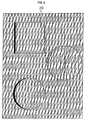
- the grid image 20 is, as shown in Fig. 4, deformed in accordance with the three-dimensional shapes of the objects to be measured 6a, 6b and 7.
- three patterns of the one-dimensional grids 1, 2 and 3, of which the periodic ratio in the horizontal direction d1:d2:d3 is 3:5:7, and which are composed of a plurality of lines extending in the vertical direction or in the oblique directions, are superimposed upon each other.
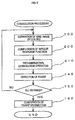
- the grid image pattern from the image sensor 21 is inputted into the image processing circuit 22, where processing as shown in Fig. 7 is executed.
- a grid image of each color is first separated from the entire grid image 20 comprising a plurality of grid images of different colors superimposed (step 100).
- image data corresponding to each grid image separated by colors are two-dimensionally Fourier transformed, thereby obtaining the intensity distribution of spatial frequency spectrums (step 110).
- Fig. 5 Shown in Fig. 5 is a perspective view of the intensity distribution of the spatial frequency spectrums obtained by the two-dimensional Fourier transform.
- Spatial frequency spectrums 13 and 13' of the one-dimensional red grid 1, spatial frequency spectrums 14 and 14' of the one-dimensional green grid 2, and spatial frequency spectrums 15 and 15' of the one-dimensional blue grid 3 are separated as shown in Fig. 5, in a two-dimensional spatial frequency domain.
- spectral components corresponding to the spatial frequency spectrums of each of the one-dimensional grids 1, 2 and 3 can be selectively extracted by means of a spatial frequency filter (step 120).
- a two-dimensional inverse Fourier transform is performed with respect to the spatial frequency spectrum selectively extracted (step 130), and then, a phase is heterodyne-detected (step 140).
- a phase is heterodyne-detected (step 140).
- step 150 the height distribution is obtained using an existing method (step 160).
- a congruence method or a coincidence method for use in a multiwavelength interference measurement, or any other method currently existing can be used.
- the heterodyne-detected phases are folded in the range of the principal value of [- ⁇ , ⁇ ]. Since the measurement sensitivities for transforming the height of the objects to be measured 6a, 6b and 7 into the phase value are differently set in the ratio of 3:5:7, correspondingly to the periodic ratio in the horizontal direction of the one-dimensional grids 1, 2 and 3, three-dimensional shape distributions folded in the ranges of different heights are obtained for each of the frequency spectrums, as shown in Figs. 6A, 6B and 6C.
- a three-dimensional shape distribution 25 as shown in Fig. 6A is a height distribution obtained by extracting the spectral component 13 of the one-dimensional red grid 1, comprising lines extending in the vertical direction, by means of a filter, and then, performing a heterodyne detection.
- the three-dimensional shape distribution 25 is folded in the range of 3mm high.
- a three-dimensional shape distribution 26 as shown in Fig. 6B is a height distribution obtained by extracting the spectral component 14 of the one-dimensional green grid 2, comprising lines extending in an oblique direction, by means of a filter, and then, performing a heterodyne detection.
- the three-dimensional shape distribution 26 is folded in the range of 5mm high.
- a three-dimensional shape distribution 27 as shown in Fig. 6C is a height distribution obtained by extracting the spectral component 15 of the one-dimensional blue grid 3, comprising lines extending in an oblique direction, by means of a filter, and then, performing a heterodyne detection.
- the three-dimensional shape distribution 27 is folded in the range of 7mm high. In these manners, it is possible to simultaneously obtain a plurality of measurement data, in accordance with three different sensitivities, from the grid images of the one-dimensional grids 1, 2 and 3 of different colors as shown in Figs. 1A, 1B and 1C. If more grid patterns of various colors are multiplexed, even more data measured in accordance with different sensitivities can be obtained.
- any one of the height distributions 25, 26 and 27 folded as shown in Figs. 6A, 6B and 6C, respectively, is only obtained.
- objects to be measured having large discontinuous steps along their edges and composed of isolated faces having no mutual contact points, such as the objects to be measured 6a and 6b in Fig. 3, it is impossible to uniquely determine the three-dimensional shapes thereof in view of any one of the height distributions 25, 26 and 27. Accordingly, it is essential to simultaneously obtain a plurality of measurement data, in accordance with a plurality of different sensitivities, from the grid image 20 comprising a plurality of one-dimensional grids of different colors, like the method of the invention.
- the congruence method As a method of determining a three-dimensional shape by integrating the data of the three height distributions 25, 26 and 27, as shown in Figs. 6A, 6B and 6C, respectively, folded in the height sensitivity ratio of 3:5:7, the congruence method, which is well known in the field of multiwavelength interference measurement, may be used. Using this method, the three-dimensional shape distributions of the objects to be measured 6a, 6b and 7, as shown in Fig. 3, can be precisely obtained.
- each grid image is first separated by colors from the superimposed grid image 20 (step 100).
- a two-dimensional filter window function used in selective extraction of desired spectrums is inversely-Fourier transformed in order to obtain a two-dimensional impulse response function (step 200).
- a direct, two-dimensional convolution operation is carried out with respect to the grid image 20 (step 210).
- the spectral components corresponding to the respective spatial frequencies of the one-dimensional grids 1, 2 and 3 can be selectively extracted.
- the spatial frequency multiplexed grid image 20 deformed in accordance with the respective three-dimensional shapes of the objects to be measured 6a, 6b and 7 is imported into the image processing circuit 22, and a grid image of each color is separated from the entire grid image 20, and the spectral components corresponding to the respective spatial frequencies of the one-dimensional grids 1, 2 and 3 are selectively extracted by means of the spatial frequency filter, and then, the phases of the spectral components are individually heterodyne-detected.
- This processing of spatial frequency filtering may be carried out in a frequency spectral region, where the deformed grid image is two-dimensionally Fourier-transformed. Otherwise, the two-dimensional convolution operation equivalent to such processing may be directly performed in relation to the two-dimensional grid image.
- the heterodyne-detected phases are folded in the range of the principal value of [- ⁇ , ⁇ ]. Since the measuring sensitivities for transforming the height of the objects to be measured 6a, 6b and 7 into the phase value are different depending on the spatial frequencies of the one-dimensional grids 1, 2 and 3, various three-dimensional shape distributions are obtained in which the phases are folded in the ranges of different heights depending on each frequency spectrum.
- a ring-shaped white color source 31 is disposed coaxially relative to the image sensor 21, such that white light is projected upon the objects to be measured 6a, 6b and 7 from the white color source 31, while color images of the objects to be measured 6a, 6b and 7 are imaged by the image sensor 21. From each pixel of the color images, color information of the objects to be measured is obtained. In this manner, the color information as well as the measurement data on the three-dimensional shape can be obtained at the same time.
- the three-dimensional shape measuring method of the invention it is possible to instantaneously measure the three-dimensional shape of an object having large discontinuous steps or composed of isolated faces having no mutual contact points, by only one-time projection of grid patterns upon the object. Consequently, measurement of an instantaneous shape of a discontinuous object during its high-speed movement or high-speed deformation is also made possible, which has been difficult according to the conventional measuring methods.
- the entire grid image is separated by colors and, therefore, each individual grid image after separation has no portion where the grid images of different colors intersect. Consequently, the noise generated by the grid images of the other one-dimensional grids can be abated, which results in a high-precision measurement of the shape.
- a three-dimensional shape measuring method by which measurement of a three-dimensional shape is realized with an improved precision.
- Grid patterns comprising a plurality of one-dimensional grids 1, 2 and 3, each having a period and direction different from those of the others, are simultaneously projected upon objects to be measured, using different colors for each of the one-dimensional grids 1, 2 and 3.
- a grid image deformed in accordance with the three-dimensional shapes of the objects to be measured is imaged, the grid image is separated by colors into one-dimensional grid components of each color, a phase for each of the one-dimensional grid components is detected, and then, measurement values of the three-dimensional shapes are obtained on the basis of the detected phases.
- color information on the objects to be measured are measured as well.
Landscapes
- Physics & Mathematics (AREA)
- Engineering & Computer Science (AREA)
- General Physics & Mathematics (AREA)
- Computer Vision & Pattern Recognition (AREA)
- Optics & Photonics (AREA)
- Theoretical Computer Science (AREA)
- Length Measuring Devices By Optical Means (AREA)
- Image Analysis (AREA)
- Image Processing (AREA)
Abstract
Description

Claims (12)
- A method for obtaining a measurement value of a three-dimensional shape of an object, using a grid image formed by projecting a plurality of grid patterns upon the object to be measured, the method comprising the steps of:projecting the grid patterns upon the object to be measured, the grid patterns comprising a plurality of one-dimensional grids of different colors, each having a distinctive period and direction;imaging the grid patterns deformed in accordance with the three-dimensional shape of the object to be measured;separating from the grid image each of the one-dimensional grids of different colors;detecting a phase for each of the one-dimensional grids; andobtaining the measurement value on the basis of the detected phases.
- The method for obtaining a measurement value of a three-dimensional shape of an object as recited in claim 1, wherein the colors of the one-dimensional grids of different colors are red, green and blue.
- The method for obtaining a measurement value of a three-dimensional shape of an object as recited in claim 2, wherein the colors of the one-dimensional grids of different colors are projected through a plurality of prism mechanisms by a plurality of white light sources.
- The method for obtaining a measurement value of a three-dimensional shape of an object as recited in claim 2, wherein the grid patterns comprise dots.
- The method for obtaining a measurement value of a three-dimensional shape of an object as recited in claim 1, wherein the grid patterns comprise sinusoidal lines.
- The method for obtaining a measurement value of a three-dimensional shape of an object as recited in claim 1, wherein a straight line connecting a center of a projection lens which projects the grid patterns with a center of an image formation lens which senses the images of the grid patterns is parallel to a reference surface on which the object to be measured is placed.
- The method for obtaining a measurement value of a three-dimensional shape of an object as recited in claim 6, wherein an optical axis of the image formation lens is perpendicular to the reference surface.
- The method for obtaining a measurement value of a three-dimensional shape of an object as recited in claim 1, further comprising the step of measuring color information of the object to be measured by imaging the object using white light.
- The method for obtaining a measurement value of a three-dimensional shape of an object as recited in claim 1, wherein the phases for each of the one-dimensional grids have periods that when compared to each other have ratios represented by prime numbers.
- The method for obtaining a measurement value of a three-dimensional shape of an object as recited in claim 9, wherein a measurement sensitivity ratio for transforming a height of the object into a phase value is determined from a periodic ratio in a horizontal direction of the one-dimensional grids.
- A method for obtaining a measurement value of a three-dimensional shape of an object, using a grid image formed by projecting a plurality of grid patterns upon the object to be measured, the method comprising the steps of:projecting the grid patterns upon the object to be measured, the grid patterns comprising a plurality of one-dimensional grids of different colors, each having a distinctive period and direction;imaging the grid patterns deformed in accordance with the three-dimensional shape of the object to be measured;separating from the grid image each of the one-dimensional grid components of different colors;obtaining an intensity distribution of spatial frequency spectrums through Fourier-transformation;selectively extracting spectral components corresponding to the spatial frequency spectrums by means of a spatial frequency filter;performing an inverse two-dimensional Fourier transform on the selected spectral component;detecting a phase for each of the one-dimensional grid components; andobtaining the measurement value on the basis of the detected phases.
- A method for obtaining a measurement value of a three-dimensional shape of an object, using a grid image formed by projecting a plurality of grid patterns upon the object to be measured, the method comprising the steps of:projecting the grid patterns upon the object to be measured, the grid patterns comprising a plurality of one-dimensional grids of different colors, each having a distinctive period and direction;imaging the grid patterns deformed in accordance with the three-dimensional shape of the object to be measured;separating from the grid image each of the one-dimensional grid components of different colors;extracting, selectively, through a two-dimensional filter window function a desired spectrum and inversely Fourier transforming the spectrum to obtain a two-dimensional impulse response function;carrying out a direct, two-dimensional convolution operation on the two-dimensional impulse response function to obtain spectral components corresponding to the one-dimensional grid components;detecting a phase for each of the one-dimensional grid components; andobtaining the measurement value on the basis of the detected phases.
Applications Claiming Priority (2)
| Application Number | Priority Date | Filing Date | Title |
|---|---|---|---|
| JP2001122723A JP3519698B2 (en) | 2001-04-20 | 2001-04-20 | 3D shape measurement method |
| JP2001122723 | 2001-04-20 |
Publications (2)
| Publication Number | Publication Date |
|---|---|
| EP1251327A2 true EP1251327A2 (en) | 2002-10-23 |
| EP1251327A3 EP1251327A3 (en) | 2008-01-09 |
Family
ID=18972388
Family Applications (1)
| Application Number | Title | Priority Date | Filing Date |
|---|---|---|---|
| EP01128130A Withdrawn EP1251327A3 (en) | 2001-04-20 | 2001-11-27 | Three-dimensional shape measuring method |
Country Status (5)
| Country | Link |
|---|---|
| US (1) | US6750975B2 (en) |
| EP (1) | EP1251327A3 (en) |
| JP (1) | JP3519698B2 (en) |
| KR (1) | KR100613421B1 (en) |
| NO (1) | NO20021457L (en) |
Cited By (7)
| Publication number | Priority date | Publication date | Assignee | Title |
|---|---|---|---|---|
| WO2004111571A1 (en) * | 2003-06-12 | 2004-12-23 | UNIVERZA V LJUBLJANI, Fakulteta za strojnistvo | Apparatus for determining shape and size of three-dimensional objects |
| EP1420281A3 (en) * | 2002-11-15 | 2005-06-01 | CARL ZEISS JENA GmbH | Method and apparatus for optical scanning with a large depth of field |
| CN103890543A (en) * | 2011-11-23 | 2014-06-25 | 纽约市哥伦比亚大学理事会 | Systems, methods, and media for performing shape measurement |
| WO2015135952A1 (en) * | 2014-03-12 | 2015-09-17 | Vit | Method for determining three-dimensional images of an object |
| EP2496910A4 (en) * | 2009-11-04 | 2016-11-16 | Technologies Numetrix Inc | Device and method for obtaining three-dimensional object surface data |
| EP3441715A4 (en) * | 2016-04-06 | 2019-11-13 | 4d Sensor Inc. | MEASURING METHOD, MEASURING DEVICE, MEASURING PROGRAM, AND COMPUTER-READABLE RECORDING MEDIUM HAVING THE MEASUREMENT PROGRAM RECORDED THEREON |
| WO2026024299A1 (en) * | 2024-07-23 | 2026-01-29 | Nikon Corporation | Systems and methods for improved optical fringe generation and projection |
Families Citing this family (60)
| Publication number | Priority date | Publication date | Assignee | Title |
|---|---|---|---|---|
| US6937348B2 (en) * | 2000-01-28 | 2005-08-30 | Genex Technologies, Inc. | Method and apparatus for generating structural pattern illumination |
| KR100406843B1 (en) * | 2001-04-06 | 2003-11-21 | (주) 인텍플러스 | Real time 3D surface shape measurement method and device using color information |
| JP3884321B2 (en) * | 2001-06-26 | 2007-02-21 | オリンパス株式会社 | 3D information acquisition apparatus, projection pattern in 3D information acquisition, and 3D information acquisition method |
| JP3855756B2 (en) * | 2001-12-07 | 2006-12-13 | ブラザー工業株式会社 | 3D color shape detection device and 3D scanner |
| WO2005031252A1 (en) * | 2003-09-25 | 2005-04-07 | Brother Kogyo Kabushiki Kaisha | Three-dimensional shape determining apparatus, three-dimensional shape determining system, and three-dimensional shape determining program |
| JP4162095B2 (en) * | 2003-12-11 | 2008-10-08 | ストライダー ラブス,インコーポレイテッド | A technique for predicting the surface of a shielded part by calculating symmetry. |
| JP2005293075A (en) * | 2004-03-31 | 2005-10-20 | Brother Ind Ltd | 3D shape detection device, 3D shape detection method, 3D shape detection program |
| US20050243330A1 (en) * | 2004-04-28 | 2005-11-03 | Simon Magarill | Methods and apparatus for determining three dimensional configurations |
| US7433058B2 (en) * | 2004-07-12 | 2008-10-07 | Solvision Inc. | System and method for simultaneous 3D height measurements on multiple sides of an object |
| JP4613626B2 (en) * | 2005-02-04 | 2011-01-19 | 旭硝子株式会社 | Mirror surface shape measuring method and apparatus, and inspection method and apparatus |
| US7285767B2 (en) * | 2005-10-24 | 2007-10-23 | General Electric Company | Methods and apparatus for inspecting an object |
| JP5091466B2 (en) * | 2005-11-30 | 2012-12-05 | 国立大学法人浜松医科大学 | Observation device |
| US20070273894A1 (en) * | 2006-05-23 | 2007-11-29 | Johnson James T | Method and apparatus for remote spatial calibration and imaging |
| US7474415B2 (en) * | 2006-09-13 | 2009-01-06 | Chung Shan Institute Of Science And Technology, Armaments Bureau, M.N.D. | Measurement method of three-dimensional profiles and reconstruction system thereof using subpixel localization with color gratings and picture-in-picture switching on single display |
| KR100945314B1 (en) | 2007-02-21 | 2010-03-05 | 캐논 가부시끼가이샤 | Shape Measuring Device, Exposure Device and Computer |
| DE102007034689B4 (en) * | 2007-07-12 | 2009-06-10 | Carl Zeiss Ag | Method and device for optically inspecting a surface on an object |
| US7768656B2 (en) * | 2007-08-28 | 2010-08-03 | Artec Group, Inc. | System and method for three-dimensional measurement of the shape of material objects |
| WO2009038242A1 (en) * | 2007-09-18 | 2009-03-26 | Intekplus Co., Ltd. | Optical test method |
| JP4633101B2 (en) * | 2007-10-15 | 2011-02-16 | ビジュアツール株式会社 | Three-dimensional shape measuring apparatus and three-dimensional shape measuring method |
| DE102007054907A1 (en) * | 2007-11-15 | 2009-05-28 | Sirona Dental Systems Gmbh | Method for the optical measurement of objects using a triangulation method |
| CN101960253B (en) | 2008-02-26 | 2013-05-01 | 株式会社高永科技 | Three-dimensional shape measuring device and measuring method |
| KR100901537B1 (en) | 2008-04-30 | 2009-06-08 | 지스캔(주) | 3D measurement method using color grid |
| KR100910573B1 (en) | 2008-05-29 | 2009-08-04 | 선문대학교 산학협력단 | 3D Measurement Method Using Color Multiwavelength Phase |
| WO2010006081A1 (en) * | 2008-07-08 | 2010-01-14 | Chiaro Technologies, Inc. | Multiple channel locating |
| KR101001894B1 (en) | 2008-10-13 | 2010-12-17 | 한국표준과학연구원 | 3D shape measurement device and method using color projection moire technique |
| KR101078877B1 (en) | 2009-02-18 | 2011-11-01 | 연세대학교 산학협력단 | Apparatus for measuring three-dimensional shape |
| KR101078876B1 (en) | 2009-02-18 | 2011-11-01 | 연세대학교 산학협력단 | Apparatus for measuring three-dimensional shape |
| DE102009017464B4 (en) * | 2009-04-03 | 2011-02-17 | Carl Zeiss Oim Gmbh | Device for optically inspecting a surface on an object |
| KR101088497B1 (en) | 2009-05-21 | 2011-11-30 | 주식회사 고영테크놀러지 | 3D shape measurement method |
| JP5395507B2 (en) * | 2009-05-21 | 2014-01-22 | キヤノン株式会社 | Three-dimensional shape measuring apparatus, three-dimensional shape measuring method, and computer program |
| WO2012050107A1 (en) * | 2010-10-12 | 2012-04-19 | グローリー株式会社 | Coin processing device and coin processing method |
| KR101289595B1 (en) * | 2011-02-28 | 2013-07-24 | 이경자 | Grid pattern projection device |
| KR101295760B1 (en) * | 2011-03-10 | 2013-08-13 | 주식회사 미르기술 | Vision inspection apparatus using multiple grid pattern |
| KR101466741B1 (en) * | 2011-06-28 | 2014-12-01 | 주식회사 고영테크놀러지 | Method for measuring three dimensional shape |
| US8964002B2 (en) | 2011-07-08 | 2015-02-24 | Carestream Health, Inc. | Method and apparatus for mapping in stereo imaging |
| JP5581282B2 (en) * | 2011-08-31 | 2014-08-27 | 株式会社日立ハイテクノロジーズ | Surface shape measuring device |
| US8990682B1 (en) * | 2011-10-05 | 2015-03-24 | Google Inc. | Methods and devices for rendering interactions between virtual and physical objects on a substantially transparent display |
| WO2013118543A1 (en) * | 2012-02-09 | 2013-08-15 | 株式会社 日立ハイテクノロジーズ | Surface measurement device |
| JP5995484B2 (en) * | 2012-03-30 | 2016-09-21 | キヤノン株式会社 | Three-dimensional shape measuring apparatus, three-dimensional shape measuring method, and program |
| JP6104662B2 (en) * | 2013-03-25 | 2017-03-29 | 株式会社東芝 | Measuring device, method and program |
| US20140293011A1 (en) * | 2013-03-28 | 2014-10-02 | Phasica, LLC | Scanner System for Determining the Three Dimensional Shape of an Object and Method for Using |
| KR101606720B1 (en) * | 2013-08-12 | 2016-03-28 | 주식회사 수아랩 | Three-dimensional surface measuring apparatus and method thereof |
| JP6232829B2 (en) * | 2013-08-13 | 2017-11-22 | 横浜ゴム株式会社 | Shape analysis apparatus and shape analysis method |
| WO2015066458A1 (en) * | 2013-11-01 | 2015-05-07 | The Research Foundation For The State University Of New York | Method for measuring the interior three-dimensional movement, stress and strain of an object |
| JP2015114309A (en) | 2013-12-16 | 2015-06-22 | 株式会社オプトン | Measuring device |
| CH709747A1 (en) | 2014-06-11 | 2015-12-15 | Quarz Partners Ag | Method and apparatus for three-dimensional measuring of tooth rows. |
| KR101447645B1 (en) | 2014-07-08 | 2014-10-08 | 주식회사 고영테크놀러지 | Method for measuring three dimensional shape |
| JP6478725B2 (en) * | 2015-03-09 | 2019-03-06 | キヤノン株式会社 | Measuring device and robot |
| US20160354881A1 (en) * | 2015-06-02 | 2016-12-08 | Canon Kabushiki Kaisha | Measurement apparatus, system, and method of manufacturing article |
| KR102482062B1 (en) * | 2016-02-05 | 2022-12-28 | 주식회사바텍 | Dental three-dimensional scanner using color pattern |
| JP6673266B2 (en) * | 2017-03-08 | 2020-03-25 | オムロン株式会社 | Mutual reflection detecting device, mutual reflection detecting method, and program |
| KR102015219B1 (en) * | 2018-04-24 | 2019-10-22 | 한국표준과학연구원 | Apparatus and method for 3D measurement of freeform surfaces based on high-speed deflectometry using composite patterns |
| KR102684986B1 (en) * | 2018-09-18 | 2024-07-16 | 서울대학교산학협력단 | Device for 3D image reconstruction using rectangular grid projection |
| CN109489583B (en) * | 2018-11-19 | 2021-09-17 | 先临三维科技股份有限公司 | Projection device, acquisition device and three-dimensional scanning system with same |
| US11486700B2 (en) * | 2019-07-29 | 2022-11-01 | Korea Research Institute Of Standards And Science | System and method for 3D shape measurement of freeform surface based on high-speed deflectometry using composite patterns |
| KR102218015B1 (en) * | 2019-08-06 | 2021-02-19 | 한국표준과학연구원 | System for measuring Grating phase using calibration Grating in FPM |
| TWI720602B (en) * | 2019-08-27 | 2021-03-01 | 國立中央大學 | Method and optical system for reconstructing surface of object |
| JP2022049269A (en) * | 2020-09-16 | 2022-03-29 | セイコーエプソン株式会社 | 3D shape measurement method and 3D shape measurement device |
| WO2022178678A1 (en) * | 2021-02-23 | 2022-09-01 | 华为技术有限公司 | Optical system, apparatus, and terminal |
| KR102485679B1 (en) * | 2021-03-05 | 2023-01-10 | 한국표준과학연구원 | Calibration method of deflectometry for improving measurement accuracy |
Family Cites Families (22)
| Publication number | Priority date | Publication date | Assignee | Title |
|---|---|---|---|---|
| US3944358A (en) * | 1974-09-20 | 1976-03-16 | Xerox Corporation | Color image reproduction system |
| JPH061164B2 (en) * | 1985-01-31 | 1994-01-05 | 伍良 松本 | Three-dimensional shape measuring device |
| JPH0615968B2 (en) * | 1986-08-11 | 1994-03-02 | 伍良 松本 | Three-dimensional shape measuring device |
| US5016040A (en) * | 1987-05-26 | 1991-05-14 | Silhouette Technology, Inc. | Method and apparatus for forming a recording on a recording medium |
| DE3907430C1 (en) * | 1988-12-23 | 1991-03-21 | Klaus 8206 Bruckmuehl De Pfister | |
| US5489986A (en) * | 1989-02-28 | 1996-02-06 | Nikon Corporation | Position detecting apparatus |
| DE4007500A1 (en) * | 1990-03-09 | 1991-09-12 | Zeiss Carl Fa | METHOD AND DEVICE FOR CONTACTLESS MEASUREMENT OF OBJECT SURFACES |
| US5343294A (en) * | 1990-03-09 | 1994-08-30 | Carl-Zeiss-Stiftung | Method for analyzing periodic brightness patterns |
| DE4130237A1 (en) * | 1991-09-11 | 1993-03-18 | Zeiss Carl Fa | METHOD AND DEVICE FOR THE THREE-DIMENSIONAL OPTICAL MEASUREMENT OF OBJECT SURFACES |
| NL9200071A (en) * | 1992-01-15 | 1993-08-02 | Stichting Science Park Maastri | DEVICE FOR DETERMINING THE TOPOGRAPHY OF A CURVED SURFACE. |
| US6153886A (en) * | 1993-02-19 | 2000-11-28 | Nikon Corporation | Alignment apparatus in projection exposure apparatus |
| US5583609A (en) * | 1993-04-23 | 1996-12-10 | Nikon Corporation | Projection exposure apparatus |
| US6028672A (en) * | 1996-09-30 | 2000-02-22 | Zheng J. Geng | High speed three dimensional imaging method |
| EP1009969B1 (en) * | 1996-06-13 | 2003-11-05 | K.U. Leuven Research & Development | Method and system for acquiring a three-dimensional shape description |
| JP3388684B2 (en) | 1997-03-05 | 2003-03-24 | 株式会社オプトン | 3D shape measurement method |
| GB9713658D0 (en) * | 1997-06-28 | 1997-09-03 | Travis Adrian R L | View-sequential holographic display |
| US6438272B1 (en) * | 1997-12-31 | 2002-08-20 | The Research Foundation Of State University Of Ny | Method and apparatus for three dimensional surface contouring using a digital video projection system |
| US6252623B1 (en) * | 1998-05-15 | 2001-06-26 | 3Dmetrics, Incorporated | Three dimensional imaging system |
| JP2000292135A (en) * | 1999-04-07 | 2000-10-20 | Minolta Co Ltd | Three-dimensional information input camera |
| JP2000292131A (en) | 1999-04-07 | 2000-10-20 | Minolta Co Ltd | Three-dimensional information input camera |
| US6341016B1 (en) * | 1999-08-06 | 2002-01-22 | Michael Malione | Method and apparatus for measuring three-dimensional shape of object |
| JP2001159510A (en) * | 1999-12-01 | 2001-06-12 | Matsushita Electric Ind Co Ltd | Three-dimensional shape measuring method and device |
-
2001
- 2001-04-20 JP JP2001122723A patent/JP3519698B2/en not_active Expired - Fee Related
- 2001-11-27 EP EP01128130A patent/EP1251327A3/en not_active Withdrawn
- 2001-11-27 US US09/995,128 patent/US6750975B2/en not_active Expired - Fee Related
- 2001-11-30 KR KR1020010075435A patent/KR100613421B1/en not_active Expired - Fee Related
-
2002
- 2002-03-22 NO NO20021457A patent/NO20021457L/en not_active Application Discontinuation
Cited By (9)
| Publication number | Priority date | Publication date | Assignee | Title |
|---|---|---|---|---|
| EP1420281A3 (en) * | 2002-11-15 | 2005-06-01 | CARL ZEISS JENA GmbH | Method and apparatus for optical scanning with a large depth of field |
| WO2004111571A1 (en) * | 2003-06-12 | 2004-12-23 | UNIVERZA V LJUBLJANI, Fakulteta za strojnistvo | Apparatus for determining shape and size of three-dimensional objects |
| EP2496910A4 (en) * | 2009-11-04 | 2016-11-16 | Technologies Numetrix Inc | Device and method for obtaining three-dimensional object surface data |
| CN103890543A (en) * | 2011-11-23 | 2014-06-25 | 纽约市哥伦比亚大学理事会 | Systems, methods, and media for performing shape measurement |
| WO2015135952A1 (en) * | 2014-03-12 | 2015-09-17 | Vit | Method for determining three-dimensional images of an object |
| FR3018621A1 (en) * | 2014-03-12 | 2015-09-18 | Vit | METHOD FOR DETERMINING THREE DIMENSIONAL IMAGES OF AN OBJECT |
| EP3441715A4 (en) * | 2016-04-06 | 2019-11-13 | 4d Sensor Inc. | MEASURING METHOD, MEASURING DEVICE, MEASURING PROGRAM, AND COMPUTER-READABLE RECORDING MEDIUM HAVING THE MEASUREMENT PROGRAM RECORDED THEREON |
| US10551177B2 (en) | 2016-04-06 | 2020-02-04 | 4D Sensor Inc. | Apparatus and method for measuring 3D form or deformation of an object surface using a grid pattern and reference plane |
| WO2026024299A1 (en) * | 2024-07-23 | 2026-01-29 | Nikon Corporation | Systems and methods for improved optical fringe generation and projection |
Also Published As
| Publication number | Publication date |
|---|---|
| EP1251327A3 (en) | 2008-01-09 |
| NO20021457L (en) | 2002-10-21 |
| KR100613421B1 (en) | 2006-08-17 |
| JP2002318109A (en) | 2002-10-31 |
| US20030016366A1 (en) | 2003-01-23 |
| US6750975B2 (en) | 2004-06-15 |
| JP3519698B2 (en) | 2004-04-19 |
| NO20021457D0 (en) | 2002-03-22 |
| KR20020082738A (en) | 2002-10-31 |
Similar Documents
| Publication | Publication Date | Title |
|---|---|---|
| EP1251327A2 (en) | Three-dimensional shape measuring method | |
| US6084712A (en) | Three dimensional imaging using a refractive optic design | |
| US9810530B2 (en) | Autofocus system and method | |
| US4842411A (en) | Method of automatically measuring the shape of a continuous surface | |
| EP1330790B1 (en) | Accurately aligning images in digital imaging systems by matching points in the images | |
| US20150237329A1 (en) | Systems and Methods for Estimating Depth Using Ad Hoc Stereo Array Cameras | |
| WO2000070303A1 (en) | Color structured light 3d-imaging system | |
| WO2007043036A1 (en) | Method and system for object reconstruction | |
| US6876458B2 (en) | Method and device for determining the absolute coordinates of an object | |
| JP2930406B2 (en) | Method and apparatus for observing a moiré pattern on a surface to be tested by applying a moiré method utilizing phase shift | |
| JP6091318B2 (en) | Ranging device and control method thereof | |
| JP4403477B2 (en) | Image processing apparatus and image processing method | |
| US20160301855A1 (en) | Imaging device and phase difference detection method | |
| JP3388684B2 (en) | 3D shape measurement method | |
| JP5500879B2 (en) | Image processing apparatus and image processing method | |
| JP2013024653A (en) | Distance measuring apparatus and program | |
| JP2003346130A (en) | Three-dimensional information processor and three- dimensional information processing method | |
| KR20000053779A (en) | Three dimension measuring system using two dimensional linear grid patterns | |
| JP4792833B2 (en) | Overlay measuring device | |
| JP2001027517A (en) | Noncontact shape measuring method | |
| JP2001356010A (en) | Three-dimensional shape measuring apparatus | |
| JP3488762B2 (en) | Image processing apparatus and image processing method | |
| JP2008170281A (en) | Shape measuring apparatus and shape measuring method | |
| JP2001349713A (en) | Three-dimensional shape measuring device | |
| CN117999792A (en) | Information processing device, method, program, and image pickup device |
Legal Events
| Date | Code | Title | Description |
|---|---|---|---|
| PUAI | Public reference made under article 153(3) epc to a published international application that has entered the european phase |
Free format text: ORIGINAL CODE: 0009012 |
|
| AK | Designated contracting states |
Kind code of ref document: A2 Designated state(s): AT BE CH CY DE DK ES FI FR GB GR IE IT LI LU MC NL PT SE TR |
|
| AX | Request for extension of the european patent |
Free format text: AL;LT;LV;MK;RO;SI |
|
| 17P | Request for examination filed |
Effective date: 20041209 |
|
| PUAL | Search report despatched |
Free format text: ORIGINAL CODE: 0009013 |
|
| AK | Designated contracting states |
Kind code of ref document: A3 Designated state(s): AT BE CH CY DE DK ES FI FR GB GR IE IT LI LU MC NL PT SE TR |
|
| AX | Request for extension of the european patent |
Extension state: AL LT LV MK RO SI |
|
| RIC1 | Information provided on ipc code assigned before grant |
Ipc: G01B 7/28 20060101ALI20071205BHEP Ipc: G01B 11/25 20060101AFI20071205BHEP |
|
| AKX | Designation fees paid |
Designated state(s): DE FR GB IT |
|
| 17Q | First examination report despatched |
Effective date: 20101221 |
|
| STAA | Information on the status of an ep patent application or granted ep patent |
Free format text: STATUS: THE APPLICATION IS DEEMED TO BE WITHDRAWN |
|
| 18D | Application deemed to be withdrawn |
Effective date: 20110503 |