EP1254855A2 - Vorrichtung zum Abbau eines Stapels flacher, biegsamer Gegenstände und Stützvorrichtung - Google Patents
Vorrichtung zum Abbau eines Stapels flacher, biegsamer Gegenstände und Stützvorrichtung Download PDFInfo
- Publication number
- EP1254855A2 EP1254855A2 EP02005716A EP02005716A EP1254855A2 EP 1254855 A2 EP1254855 A2 EP 1254855A2 EP 02005716 A EP02005716 A EP 02005716A EP 02005716 A EP02005716 A EP 02005716A EP 1254855 A2 EP1254855 A2 EP 1254855A2
- Authority
- EP
- European Patent Office
- Prior art keywords
- orbit
- stack
- support
- support elements
- rollers
- Prior art date
- Legal status (The legal status is an assumption and is not a legal conclusion. Google has not performed a legal analysis and makes no representation as to the accuracy of the status listed.)
- Granted
Links
Images


Classifications
-
- B—PERFORMING OPERATIONS; TRANSPORTING
- B65—CONVEYING; PACKING; STORING; HANDLING THIN OR FILAMENTARY MATERIAL
- B65H—HANDLING THIN OR FILAMENTARY MATERIAL, e.g. SHEETS, WEBS, CABLES
- B65H3/00—Separating articles from piles
- B65H3/32—Separating articles from piles by elements, e.g. fingers, plates, rollers, inserted or traversed between articles to be separated and remainder of the pile
-
- B—PERFORMING OPERATIONS; TRANSPORTING
- B65—CONVEYING; PACKING; STORING; HANDLING THIN OR FILAMENTARY MATERIAL
- B65H—HANDLING THIN OR FILAMENTARY MATERIAL, e.g. SHEETS, WEBS, CABLES
- B65H2301/00—Handling processes for sheets or webs
- B65H2301/40—Type of handling process
- B65H2301/42—Piling, depiling, handling piles
- B65H2301/423—Depiling; Separating articles from a pile
- B65H2301/4232—Depiling; Separating articles from a pile of horizontal or inclined articles, i.e. wherein articles support fully or in part the mass of other articles in the piles
- B65H2301/42322—Depiling; Separating articles from a pile of horizontal or inclined articles, i.e. wherein articles support fully or in part the mass of other articles in the piles from bottom of the pile
-
- B—PERFORMING OPERATIONS; TRANSPORTING
- B65—CONVEYING; PACKING; STORING; HANDLING THIN OR FILAMENTARY MATERIAL
- B65H—HANDLING THIN OR FILAMENTARY MATERIAL, e.g. SHEETS, WEBS, CABLES
- B65H2301/00—Handling processes for sheets or webs
- B65H2301/40—Type of handling process
- B65H2301/42—Piling, depiling, handling piles
- B65H2301/423—Depiling; Separating articles from a pile
- B65H2301/4233—Depiling; Separating articles from a pile by peeling, i.e. involving elongated elements traversing pile
Definitions
- the invention relates to a device for breaking down a Stack of flat, flexible objects according to the Preamble of claim 1 and a support device for such a dismantling device according to claim 13.
- a generic dismantling device is from CH 598 106 known. It comprises a support device from one another spaced, along a closed orbit moved, freely rotatable about its longitudinal axis Rollers.
- the rollers form part of the support device a roll-carpet edition, on which a stack of flat objects rests.
- the Rollers are moved under the stack, with the Stack always rests on several of the rollers.
- On clocked driven suction element reaches through the Spaces between two rollers from below on the Stack and lift one corner of the bottom one at the moment lying product from the rest of the stack.
- the overall arrangement consisting from the support device and the belt conveyor a significant lateral extent that the stack width far exceeds. A compact implementation of the mining device can not. If further on the Belt conveyor a scale formation with vertical or Edges of the products running parallel to the direction of conveyance to be created, the stack must be on the stack support be oriented obliquely to the rollers. So that is an object shortly before being placed on the belt conveyor just held at one corner. When dropping the item it can therefore be particularly difficult at high speeds to twists and thus to an undesirable mechanical stress on the object as well as a uneven scale formation.
- the invention has for its object a device to dismantle a stack of flat, flexible objects type mentioned in such a way that the lateral expansion of the device is minimized.
- a device to dismantle a stack of flat, flexible objects type mentioned in such a way that the lateral expansion of the device is minimized.
- the objects should also be at high speeds reliably in a defined orientation
- Belt conveyors can be handed over.
- the product stack supported by several support elements from below, that slide under the stack.
- the support elements are part of a support device. You are preferred one side attached to a conveyor that runs along a closed orbit is moved.
- the support elements preferably run in a stacked support horizontal and parallel to each other. Particularly preferred their axes lie in a common horizontal plane or a slightly curved surface that the stacking pad represents.
- the support elements are preferably about their longitudinal axis freely rotatable rollers with low friction on those to be dismantled Unroll objects.
- the support elements are for example designed and driven as described in CH 598 106.
- the support elements can be pivoted in this way or sliding that their location or orientation is changeable relative to the orbit.
- an orbit becomes the orbit of the bearing points of the support elements referred to, their location relative to the funding body is unchanged.
- the plane becomes the circulation plane designated in which the orbit lies. If the orbit is a space curve that is not in one plane, the circulation level is the level through which lets the space curve approach locally.
- the area covered by the rollers is in accordance with the invention shaped so that the removal device out space from the area of the support device can be.
- the rollers are pivoted or moved and thus give the way for the Belt conveyor free.
- the belt conveyor can be directly below the stacking support can be arranged.
- the inventive The device can thus be constructed in a very compact manner.
- the Support elements parallel to the front or rear edge of the Stack oriented. Because through the invention is not necessary, the stack at an angle to the support elements put on the stacking pad. This means that a separated object always over its entire width is held until it is completely separated. He will be with Do not put down on the belt conveyor even at higher ones Degradation speeds twisted.
- the support device can be formed in one or two parts his.
- the one-piece version has a carpet made of one end pivotally attached to a conveyor Support elements available. To support the stack well, can be at their free end in the area of Stack support are supported by a rail.
- the The separating element is used, for example, as in CH 598 106 through the space between two support elements the bottom product too. It comes with one the distance and the speed of the support elements adjusted clock operated.
- roller carpets available, their rollers or support elements in the area the stacking support lie in a common plane.
- the Support elements of the first and the second roll carpet are on a first and a second funding body attached and slidable or pivotable relative to these.
- the belt conveyor is preferably between the Conveying bodies arranged.
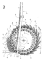
- Fig. 1 shows a side view of an inventive Device for dismantling a stack of 1 flat objects.
- the device comprises a support device 2, the one Has a plurality of rollers 3.
- the rollers are on one Wheel 12 attached via holding elements 13.
- the wheel serves as Conveyor element for the rollers 3.
- the holding element 13 held end (storage area) 3a of a roller is at Moving the wheel 12 along a closed orbit U moves, which is circular here, but also different can be shaped.
- the orbit U is in one plane, which is vertically oriented here.
- the rollers 3 are relative pivotable to the wheel 12 by the holding element 13 a base 13a fixed to the wheel and one Rotatably connected clamp 13b, which the Roller 3 in the storage area 3a holds.
- the axis of rotation D of the Pivotal movement is essentially radial or secantial direction, i.e. doesn't go straight through here the center M of the wheel 12.
- the rollers 3 are preferably mechanically by means of a link control pivoted.
- the control backdrop, not shown here acts with the holding element 13 or the roller 3 appropriate way together.
- the rollers form over a partial section A1 the orbit U is a pad 7 for the stack 1.
- the rollers in this section are parallel to each other, preferably horizontally or perpendicular to Orbital plane aligned.
- the stacking pad is present 7 curved according to the orbit U.
- the stack 1 lies on the roller carpet formed by the rollers 3 on and is laterally by vertical boundary elements 6 held in place. These preferably define a shaft, the dimensions of which correspond to the format of the processing objects can be adjusted.
- the stack 1 is dismantled from below by a separator 5 engages the front edge 4a of the object 4.
- the leading edge 4a is pulled down, for example by the separator 5 in the work area of the separator lowest object 4 sucks.
- In the resulting space drives a roller 3 and peels it from the separator bent object as it moves from Stack 1 off.
- the stack 1 is through several rollers 3 supported from below. It's not necessary, that an object is completely peeled off, before the separator 5 on another object accesses. Are present in the direction of movement of the rollers downstream several objects still with the stack connected while their upstream edges already bent away from the stack and through each other Rollers 3 are separated.
- rollers 3 When removing the stack, the rollers 3 run parallel to the front or back edge of the stack 1. The objects are therefore at all times across their entire Support and twist the width of at least one roller not at the handover to the belt conveyor 8.
- the rollers 3 are freely rotatable about their longitudinal axis and roll on the bottom of the stack or between the bottom lying objects. It can also be a means for rotating the rollers 3 in the area of the stack support 7 may be provided, for example on the conically shaped Attack the end of the rollers 3. This can cause friction further reduced between the rollers 3 and the objects become.
- Such static grater bars 20 that the Roll as they move along the orbit Setting friction into rotation are shown in FIGS. 2 and 3 shown.
- the belt conveyor 8 has a conveyor belt 9 which is parallel to the Plane of the orbit U is aligned.
- the back end 8a of the belt conveyor 8 is in the immediate vicinity spatial proximity to the movement path of the rollers below the Stacking support 7.
- the distance and the side suspension 10 of the conveyor belt 9 is selected so that the rollers 3 on rear Ehde 8a can pass.
- the drop height of one worn object i.e. the distance between that rear end 8a of the belt conveyor 8 and the rear end 7a of the stack support 7 is thus essentially through limited the diameter of a roller 3 down. she can advantageously be kept low, whereby the Objects reliably directly on the conveyor belt 9 can be filed.
- the rollers are at least where the Belt conveyor 8 in the supervision of the circulation level Orbit U crosses, pivots and thus give the way for the belt conveyor 8 free.
- the Orbit the rollers 3 are at an angle of less than 90 ° to the orbital plane. You can also in are essentially in the orbital plane.
- the belt conveyor 8 can therefore be in close proximity to the wheel 12 the area of the U orbit. He can also cross orbit twice, e.g. right and left from stack 1 to convey products under the Stack (not shown here).
- the rollers 3 are in the lower region A3 Orbit U pivoted so that it is in the plane of the Orbit.
- the support device 2 therefore has in this lower area A3 has a particularly small transverse expansion. In principle, however, it is sufficient that the Roll only in the area A2 in which the removal device 8 crosses, get out of the way.
- the Rollers can be shifted linearly or rotated as shown here be, with a swiveling movement by less than 90 ° may be sufficient.
- Fig. 2 shows a front view of an inventive Device with a support device 2 with a first and a second roller system 2a, 2b.
- the arrangement is mirror-symmetrical to a central plane M1.
- the representation 1 corresponds to a section along this Middle level M1.
- first Rollers 3 ' On a vertical first wheel 12a are first Rollers 3 'attached via holding elements 13 and are along an orbit U1 moves.
- a separator 5 engages between a first and one second roller 3 ', 3 "from below towards the stack 1, wherein the end faces of the rollers for reaching through the separating element 5 are spaced apart (distance W1). Through a trailing pair of rollers, the product is separated and falls on the belt conveyor 8. A scale formation occurs 14.
- the belt conveyor 8 is between the first and the second wheel 12a or 12b of the support device 2 arranged. According to the rollers 3 ', 3 "at the movement along their orbit U1 or U2 from their Position perpendicular to the orbital plane E1 or E2 in one orientation in the orbital plane E1 or E2 or an angle swiveled by less than 90 °.
- the width W2 between the first and second rollers 3 'or 3' 'in the area in which the removal device 8 is led out corresponds at least the width B of the belt conveyor.
- Such a stacking device is compact and slim.
- the device shown with two mirror-symmetrical Roller arrangements has the advantage of being quick Adaptation to different formats is possible by for example the distance between the circulation levels E1 and E2 or the wheels 12a, 12b are enlarged or reduced. The mechanical stability of the device is thereby easily maintained. Another advantage is that Separator 5 at any time from below onto the stack can access and no synchronization with the movement the rollers 3 ', 3 "is necessary.
- FIG. 3 shows another example of an inventive Device with a support device 2 with a Simple roller carpet.
- the structure of the support device 2 corresponds essentially to the structure of the left or right part of the support device according to FIG. 2.
- FIG. 1 corresponds to a side view of this device.
- Rollers 3 are on holding elements 13 on a wheel 12 attached and pivotable relative to this. At the top Part of the device, the rollers 3 form the stack support 7. In the lower part the rollers are swung out of the way, so that the removal device 8 is parallel to the wheel 12 or can run to the circulation plane E.
- a scaffold 15 In which the wheel 12 is mounted.
- The is also preferably supported Conveyor device 8 on the support structure 15.
- the separator 5 reaches through the spaces between two Roll 3 the bottom of the stack 1 to.
- the rollers are one essentially perpendicular to the orbit U or U1, U2 Pivoted axis. It is also possible that Realize swiveling around another axis. On Swiveling around a tangent to the orbit Axis is for example in the unpublished international patent application PCT / CH00 / 00530 and shown.
- the holder of the rollers on the support device or a funding body described in the context of present invention can also be used.
- other support elements can also be used be used, e.g. Strips, pens or the like.
Landscapes
- Engineering & Computer Science (AREA)
- Mechanical Engineering (AREA)
- Delivering By Means Of Belts And Rollers (AREA)
- Sheets, Magazines, And Separation Thereof (AREA)
- Laminated Bodies (AREA)
- Stacking Of Articles And Auxiliary Devices (AREA)
- Folding Of Thin Sheet-Like Materials, Special Discharging Devices, And Others (AREA)
- Control And Other Processes For Unpacking Of Materials (AREA)
- Supplying Of Containers To The Packaging Station (AREA)
- Tents Or Canopies (AREA)
Abstract
Description
- Fig. 1
- Eine Seitenansicht einer erfindungsgemässen Vorrichtung zum Stapelabbau;
- Fig. 2
- eine Frontansicht entgegen der Wegförderrichtung einer erfindungsgemässen Vorrichtung mit einer Stützvorrichtung mit einem zweiteiligen Walzenteppich;
- Fig. 3
- eine Frontansicht einer erfindungsgemässen Vorrichtung mit einer Stützvorrichtung mit einem einteiligen Walzenteppich.
Claims (13)
- Vorrichtung zum Abbau eines Stapels (1) flacher, biegsamer Gegenstände, insbesondere Druckereiprodukte, mit entlang einer geschlossenen Umlaufbahn (U,U1,U2) bewegten Auflageelementen (3,3',3''), die in einem ersten Teilabschnitt (A1) der Umlaufbahn (U,U1,U2) eine Stapelauflage(7) bilden, mit wenigstens einem Trennorgan (5), das einen Bereich (4a) des zuunterst im Stapel (1) liegenden Gegenstands (4) derart vom restlichen Stapel (1) abzuheben imstande ist, dass wenigstens ein in Umlaufrichtung nachlaufendes Auflageelement (3, 3', 3") zwischen den abgehobenen Gegenstand (4) und den restlichen Stapel (1) einfahren und den Gegenstand (4) bei seiner weiteren Bewegung vom restlichen Stapel (1) abtrennen kann, sowie mit einem unterhalb der Stapelauflage (7) angeordneten Bandförderer (8), auf dessen Förderband die Gegenstände nach dem Abtrennen zu liegen kommen, dadurch gekennzeichnet, dass die Auflageelemente (3, 3', 3'') derart verschwenkbar oder verschiebbar sind, dass ihre Lage relativ zur Umlaufbahn (U,U1,U2) veränderlich ist.
- Vorrichtung nach Anspruch 1, dadurch gekennzeichnet, dass die Auflageelemente (3, 3', 3'')parallel zur Vorder- bzw. Hinterkante des Stapels (1) orientiert sind.
- Vorrichtung nach Anspruch 1 oder 2, dadurch gekennzeichnet, dass die Auflageelemente um ihre Längsachse frei drehbare Walzen (3,3',3'') sind.
- Vorrichtung nach Anspruch 1, 2 oder 3, dadurch gekennzeichnet, dass die Auflageelemente (3,3',3'') derart verschwenkt oder verschoben werden, dass der Bandförderer (8) die Gegenstände in unmittelbarer räumlicher Nähe zur Umlaufbahn (U,U1,U2) aus dem durch die Umlaufbahn begrenzten Bereich hinaus zu fördern imstande ist, wobei die Umlaufbahn (U, U1, U2) vorzugsweise in einer Ebene (E,E1,E2) und der Bandförderer (8) im wesentlichen parallel dazu verläuft.
- Vorrichtung nach einem der vorangegangenen Ansprüche, dadurch gekennzeichnet, dass eine Anzahl erster Auflageelemente (3') entlang einer ersten Umlaufbahn (U1) und eine Anzahl zweiter Auflageelemente(3'') entlang einer zweiten Umlaufbahn (U2) bewegt wird, wobei die erste und die zweite Umlaufbahn (U1,U2) zumindest im Bereich der Stapelauflage (7) zueinander parallel sind.
- Vorrichtung nach Anspruch 5, dadurch gekennzeichnet, dass die ersten und zweiten Auflageelemente (3, 3', 3'') im Bereich der Stapelauflage (7) unter Bildung eines parallel zu den Umlaufbahnen (U1, U2) verlaufenden Spaltes voneinander beabstandet sind, wobei das Trennorgan (5) vorzugsweise im Bereich dieses Spaltes auf den Stapel (1) zugreift.
- Vorrichtung nach Anspruch 5 oder 6, dadurch gekennzeichnet, dass der Abstand des ersten und zweiten Auflageelements (3',3'') durch das Verschwenken oder Verschieben derart vergrössert wird, dass der Bandförderer (8) ohne mechanische Behinderung durch die Auflageelemente zwischen der ersten und der zweiten Umlaufbahn (U1,U2) aus dem durch die Umlaufbahnen (U1,U2 begrenzten Bereich geführt werden kann.
- Vorrichtung nach einem der Ansprüche 5 bis 7, dadurch gekennzeichnet, dass der Abstand der ersten und der zweiten Umlaufbahn (U1,U2) im Bereich der Stapelauflage (7) variabel ist zur Anpassung der Breite der Stapelauflage (7) an die Stapelbreite.
- Vorrichtung nach einem der vorangegangenen Ansprüche, dadurch gekennzeichnet, dass das Trennorgan (5) derart getaktet bewegt wird, dass es zwischen zwei in Umlaufrichtung aufeinanderfolgenden Auflageelementen (3,3',3'') auf den zuunterst liegenden Gegenstand (4) einwirkt.
- Vorrichtung nach einem der vorangegangenen Ansprüche, dadurch gekennzeichnet, dass die Auflageelemente (3,3',3'') im ersten Teilabschnitt der Umlaufbahn (U,U1,U2) horizontal und senkrecht zur Umlaufebene und in einem zweiten Teilabschnitt (A2, A3) der Umlaufbahn im wesentlichen in der Umlaufebene (E, E1, E2) bzw. mit einem geringen Winkel dazu ausgerichtet sind.
- Vorrichtung nach einem der vorangegangenen Ansprüche, dadurch gekennzeichnet, dass Auflageelemente (3,3',3'') um eine im wesentlichen tangential zur Umlaufbahn (U,U1,U2) verlaufende Achse in eine Ausrichtung im wesentlichen normal zur Umlaufbahn (U,U1,U2) und im wesentlichen in der Umlaufebene (E, E1, E2) geschwenkt werden oder um eine in der Umlaufebene (E, E1, E2) im wesentlichen normal zur Umlaufbahn (U,U1,U2) verlaufende Achse (D) in eine Ausrichtung im wesentlichen tangential zur Umlaufbahn (U,U1,U2) geschwenkt werden.
- Vorrichtung nach einem der vorangegangenen Ansprüche, dadurch gekennzeichnet, dass die Auflageelemente (3,3',3'') an einem entlang der Umlaufbahn (U,U1,U2) bewegten Förderorgan (12, 12a, 12b), insbesondere einer Kette oder einem Rad, befestigt sind.
- Stützvorrichtung zum Abstützen eines Stapels flacher, biegsamer Gegenstände, insbesondere Druckereiprodukte, zur Verwendung in einer Vorrichtung nach einem der Ansprüche 1 bis 12 mit entlang einer geschlossenen Umlaufbahn (U,U1,U2) bewegten Auflageelementen (3,3',3''), die in einem ersten Teilabschnitt (A1) der Umlaufbahn (U,U1,U2) eine Stapelauflage(7) bilden, wobei die Auflageelemente (3,3',3'') oder anderen derart verschwenkbar oder verschiebbar sind, dass ihre Lage relativ zur Umlaufbahn (U,U1,U2) veränderlich ist.
Applications Claiming Priority (2)
| Application Number | Priority Date | Filing Date | Title |
|---|---|---|---|
| CH7042001 | 2001-04-18 | ||
| CH7042001 | 2001-04-18 |
Publications (3)
| Publication Number | Publication Date |
|---|---|
| EP1254855A2 true EP1254855A2 (de) | 2002-11-06 |
| EP1254855A3 EP1254855A3 (de) | 2003-01-29 |
| EP1254855B1 EP1254855B1 (de) | 2006-01-25 |
Family
ID=4530255
Family Applications (1)
| Application Number | Title | Priority Date | Filing Date |
|---|---|---|---|
| EP02005716A Expired - Lifetime EP1254855B1 (de) | 2001-04-18 | 2002-03-13 | Vorrichtung zum Abbau eines Stapels flacher, biegsamer Gegenstände |
Country Status (5)
| Country | Link |
|---|---|
| US (1) | US6702276B2 (de) |
| EP (1) | EP1254855B1 (de) |
| AT (1) | ATE316507T1 (de) |
| DE (1) | DE50205681D1 (de) |
| DK (1) | DK1254855T3 (de) |
Cited By (3)
| Publication number | Priority date | Publication date | Assignee | Title |
|---|---|---|---|---|
| WO2007051324A1 (de) * | 2005-11-01 | 2007-05-10 | Ferag Ag | Verfahren und vorrichtung zum umlagern von flächigen erzeugnissen von einem erzeugnisstapel auf ein förderband |
| EP2128055A2 (de) | 2008-05-26 | 2009-12-02 | Ferag AG | Vorrichtung zum Abtrennen von einzelnen Flachen, biegbaren Gegenständen von der Unterseite eines Stapels solcher Gegenstände und zum Wegtransport der abgetrennten Gegenstände |
| CH706769A1 (de) * | 2012-07-27 | 2014-01-31 | Ferag Ag | Vorrichtung zum Abtrennen von einzelnen flachen, biegbaren Gegenständen von der Unterseite eines Stapels solcher Gegenstände. |
Families Citing this family (2)
| Publication number | Priority date | Publication date | Assignee | Title |
|---|---|---|---|---|
| CA2653884C (en) * | 2006-06-30 | 2016-02-02 | Ferag Ag | Device for separating individual flat objects from a stack and for transporting away the separated objects |
| EP2253566B1 (de) * | 2009-05-22 | 2013-07-31 | Müller Martini Holding AG | Vorrichtung zur Beschickung einer Verarbeitungsstrecke mit Druckprodukten |
Family Cites Families (8)
| Publication number | Priority date | Publication date | Assignee | Title |
|---|---|---|---|---|
| US1876606A (en) * | 1932-09-13 | bushnell | ||
| CH598106A5 (de) | 1976-07-29 | 1978-04-28 | Ferag Ag | |
| DE59007686D1 (de) * | 1989-09-13 | 1994-12-15 | Ferag Ag | Verfahren und Vorrichtung zum Weiterverarbeiten von gestapelten, vorzugsweise gefalteten Druckereierzeugnissen. |
| US5556254A (en) * | 1995-06-07 | 1996-09-17 | Standard Duplicating Machines Corporation | Paper set feeding |
| DE19549675B4 (de) * | 1995-07-07 | 2005-02-17 | Windmöller & Hölscher Kg | Verfahren zum Vereinzeln gestapelter flacher Schlauchstücke |
| IT1288191B1 (it) * | 1995-07-11 | 1998-09-11 | Windmoeller & Hoelscher | Dispositivo per singolarizzare oggetti piatti impilati. |
| NL1007943C2 (nl) * | 1997-12-31 | 1999-07-01 | Hadewe Bv | Inrichting en werkwijze voor het van een stapel separeren van vellen. |
| CA2385050C (en) * | 1999-11-02 | 2009-12-15 | Ferag Ag | Combination of suction stripper and mechanical jaws bottom de-stacking sheets to an imbricated feed line |
-
2002
- 2002-03-13 DE DE50205681T patent/DE50205681D1/de not_active Expired - Lifetime
- 2002-03-13 AT AT02005716T patent/ATE316507T1/de not_active IP Right Cessation
- 2002-03-13 DK DK02005716T patent/DK1254855T3/da active
- 2002-03-13 EP EP02005716A patent/EP1254855B1/de not_active Expired - Lifetime
- 2002-04-17 US US10/124,584 patent/US6702276B2/en not_active Expired - Lifetime
Cited By (7)
| Publication number | Priority date | Publication date | Assignee | Title |
|---|---|---|---|---|
| WO2007051324A1 (de) * | 2005-11-01 | 2007-05-10 | Ferag Ag | Verfahren und vorrichtung zum umlagern von flächigen erzeugnissen von einem erzeugnisstapel auf ein förderband |
| EP2128055A2 (de) | 2008-05-26 | 2009-12-02 | Ferag AG | Vorrichtung zum Abtrennen von einzelnen Flachen, biegbaren Gegenständen von der Unterseite eines Stapels solcher Gegenstände und zum Wegtransport der abgetrennten Gegenstände |
| US8066276B2 (en) | 2008-05-26 | 2011-11-29 | Ferag Ag | Device for separating individual flat, bendable objects from the underside of a stack of such objects and for transporting the separated objects away |
| EP2128055A3 (de) * | 2008-05-26 | 2012-01-04 | Ferag AG | Vorrichtung zum Abtrennen von einzelnen Flachen, biegbaren Gegenständen von der Unterseite eines Stapels solcher Gegenstände und zum Wegtransport der abgetrennten Gegenstände |
| AU2009202009B2 (en) * | 2008-05-26 | 2015-05-21 | Ferag Ag | Device for separating individual flat, bendable objects from the underside of a stack of such objects and for transporting the separated objects away |
| CH706769A1 (de) * | 2012-07-27 | 2014-01-31 | Ferag Ag | Vorrichtung zum Abtrennen von einzelnen flachen, biegbaren Gegenständen von der Unterseite eines Stapels solcher Gegenstände. |
| US9051142B2 (en) | 2012-07-27 | 2015-06-09 | Ferag Ag | Apparatus for separating individual flat, bendable objects from the underside of a stack of such objects |
Also Published As
| Publication number | Publication date |
|---|---|
| US6702276B2 (en) | 2004-03-09 |
| EP1254855B1 (de) | 2006-01-25 |
| US20020153653A1 (en) | 2002-10-24 |
| DK1254855T3 (da) | 2006-02-20 |
| ATE316507T1 (de) | 2006-02-15 |
| EP1254855A3 (de) | 2003-01-29 |
| DE50205681D1 (de) | 2006-04-13 |
Similar Documents
| Publication | Publication Date | Title |
|---|---|---|
| EP1944254B1 (de) | Vorrichtung zum Transport von Druckprodukten | |
| DE69503686T2 (de) | Verfahren und Vorrichtung zum Drehen von Produkten wie grafischen Produkten | |
| DE2643709A1 (de) | Sortiervorrichtung fuer ungeordnet verteiltes stueckgut | |
| DE2735163C2 (de) | Vorrichtung zum Stapeln von flachen Gegenständen, insbesondere Ziegel, in Hochkantstellung | |
| DE69831433T2 (de) | Förderer mit deformierbarem Förderband | |
| EP2531425A1 (de) | Verfahren und vorrichtung zum selektiven kippen von gegenständen | |
| DE4426085A1 (de) | Ausrichtvorrichtung für Holzstücke | |
| DE60102601T2 (de) | Verfahren und Vorrichtung zum Fördern von Gegenständen | |
| DE2849586A1 (de) | Foerdereinrichtung zum foerdern von gegenstaenden zu einer verpackungsmaschine | |
| EP1559663A1 (de) | Verfahren und Fördervorrichtung zur Förderung von mit einem Kragen versehenen Gegenständen | |
| DE9209615U1 (de) | Drehvorrichtung für Papierbogen in einer Förderbahn | |
| DE2437795A1 (de) | Vorrichtung zum entladen von dosen oder dgl. rohrfoermigen behaeltern | |
| EP4269288B1 (de) | Fördereinrichtung und verfahren zum fördern von tampon-applikatoren | |
| EP1254855A2 (de) | Vorrichtung zum Abbau eines Stapels flacher, biegsamer Gegenstände und Stützvorrichtung | |
| DE10317417B4 (de) | Vereinzelungs- und Fördervorrichtung | |
| DE9301072U1 (de) | Sammelvorrichtung für Blätter zur Bildung von Blattstapeln | |
| DE102004054490A1 (de) | Vorrichtung zum Ändern der Orientierung von Blattstapeln | |
| DE19519431C1 (de) | Vereinzelungs- und Aufgabevorrichtung für flächenartig ausgebildete Gegenstände | |
| DE4432124C2 (de) | Vorrichtung zum Vereinzeln von Zeitschriften-Remittenden von der Unterseite eines Stapels | |
| DE3937044A1 (de) | Vorrichtung zum aufbringen von deckblaettern auf blattstapel | |
| DE29601452U1 (de) | Stapelvorrichtung für kartenförmige Güter | |
| EP0806391A1 (de) | Vorrichtung zum Zubringen von Druckereierzeugnissen zu einer Weiterverarbeitungsstelle | |
| EP1218271B1 (de) | Vorrichtung zum drehen eines papierstapels | |
| DE19654857A1 (de) | Vorrichtung zum Trennen und seitlichem Auslenken durch Längsschnitt erzeugten Metallstreifen | |
| DE2109098A1 (de) | Verfahren und Vorrichtung zum Stapeln von Scheiben |
Legal Events
| Date | Code | Title | Description |
|---|---|---|---|
| PUAI | Public reference made under article 153(3) epc to a published international application that has entered the european phase |
Free format text: ORIGINAL CODE: 0009012 |
|
| AK | Designated contracting states |
Kind code of ref document: A2 Designated state(s): AT BE CH CY DE DK ES FI FR GB GR IE IT LI LU MC NL PT SE TR |
|
| AX | Request for extension of the european patent |
Free format text: AL;LT;LV;MK;RO;SI |
|
| PUAL | Search report despatched |
Free format text: ORIGINAL CODE: 0009013 |
|
| AK | Designated contracting states |
Designated state(s): AT BE CH CY DE DK ES FI FR GB GR IE IT LI LU MC NL PT SE TR |
|
| AX | Request for extension of the european patent |
Extension state: AL LT LV MK RO SI |
|
| 17P | Request for examination filed |
Effective date: 20030201 |
|
| AKX | Designation fees paid |
Designated state(s): AT BE CH CY DE DK ES FI FR GB GR IE IT LI LU MC NL PT SE TR |
|
| 17Q | First examination report despatched |
Effective date: 20040920 |
|
| GRAP | Despatch of communication of intention to grant a patent |
Free format text: ORIGINAL CODE: EPIDOSNIGR1 |
|
| GRAC | Information related to communication of intention to grant a patent modified |
Free format text: ORIGINAL CODE: EPIDOSCIGR1 |
|
| RTI1 | Title (correction) |
Free format text: DEVICE FOR DISASSAMBLING A PILE OF FLAT AND FLEXIBLE OBJECTS |
|
| GRAS | Grant fee paid |
Free format text: ORIGINAL CODE: EPIDOSNIGR3 |
|
| GRAA | (expected) grant |
Free format text: ORIGINAL CODE: 0009210 |
|
| AK | Designated contracting states |
Kind code of ref document: B1 Designated state(s): AT BE CH CY DE DK ES FI FR GB GR IE IT LI LU MC NL PT SE TR |
|
| PG25 | Lapsed in a contracting state [announced via postgrant information from national office to epo] |
Ref country code: IT Free format text: LAPSE BECAUSE OF FAILURE TO SUBMIT A TRANSLATION OF THE DESCRIPTION OR TO PAY THE FEE WITHIN THE PRESCRIBED TIME-LIMIT;WARNING: LAPSES OF ITALIAN PATENTS WITH EFFECTIVE DATE BEFORE 2007 MAY HAVE OCCURRED AT ANY TIME BEFORE 2007. THE CORRECT EFFECTIVE DATE MAY BE DIFFERENT FROM THE ONE RECORDED. Effective date: 20060125 Ref country code: NL Free format text: LAPSE BECAUSE OF FAILURE TO SUBMIT A TRANSLATION OF THE DESCRIPTION OR TO PAY THE FEE WITHIN THE PRESCRIBED TIME-LIMIT Effective date: 20060125 Ref country code: FI Free format text: LAPSE BECAUSE OF FAILURE TO SUBMIT A TRANSLATION OF THE DESCRIPTION OR TO PAY THE FEE WITHIN THE PRESCRIBED TIME-LIMIT Effective date: 20060125 Ref country code: IE Free format text: LAPSE BECAUSE OF FAILURE TO SUBMIT A TRANSLATION OF THE DESCRIPTION OR TO PAY THE FEE WITHIN THE PRESCRIBED TIME-LIMIT Effective date: 20060125 |
|
| REG | Reference to a national code |
Ref country code: GB Ref legal event code: FG4D Free format text: NOT ENGLISH |
|
| REG | Reference to a national code |
Ref country code: CH Ref legal event code: EP Ref country code: CH Ref legal event code: NV Representative=s name: PATENTANWAELTE SCHAAD, BALASS, MENZL & PARTNER AG |
|
| REG | Reference to a national code |
Ref country code: DK Ref legal event code: T3 |
|
| REG | Reference to a national code |
Ref country code: SE Ref legal event code: TRGR |
|
| REG | Reference to a national code |
Ref country code: IE Ref legal event code: FG4D Free format text: LANGUAGE OF EP DOCUMENT: GERMAN |
|
| PG25 | Lapsed in a contracting state [announced via postgrant information from national office to epo] |
Ref country code: AT Free format text: LAPSE BECAUSE OF NON-PAYMENT OF DUE FEES Effective date: 20060313 |
|
| PG25 | Lapsed in a contracting state [announced via postgrant information from national office to epo] |
Ref country code: BE Free format text: LAPSE BECAUSE OF NON-PAYMENT OF DUE FEES Effective date: 20060331 Ref country code: MC Free format text: LAPSE BECAUSE OF NON-PAYMENT OF DUE FEES Effective date: 20060331 Ref country code: LU Free format text: LAPSE BECAUSE OF NON-PAYMENT OF DUE FEES Effective date: 20060331 |
|
| GBT | Gb: translation of ep patent filed (gb section 77(6)(a)/1977) |
Effective date: 20060315 |
|
| REF | Corresponds to: |
Ref document number: 50205681 Country of ref document: DE Date of ref document: 20060413 Kind code of ref document: P |
|
| PG25 | Lapsed in a contracting state [announced via postgrant information from national office to epo] |
Ref country code: ES Free format text: LAPSE BECAUSE OF FAILURE TO SUBMIT A TRANSLATION OF THE DESCRIPTION OR TO PAY THE FEE WITHIN THE PRESCRIBED TIME-LIMIT Effective date: 20060506 |
|
| PG25 | Lapsed in a contracting state [announced via postgrant information from national office to epo] |
Ref country code: PT Free format text: LAPSE BECAUSE OF FAILURE TO SUBMIT A TRANSLATION OF THE DESCRIPTION OR TO PAY THE FEE WITHIN THE PRESCRIBED TIME-LIMIT Effective date: 20060626 |
|
| NLV1 | Nl: lapsed or annulled due to failure to fulfill the requirements of art. 29p and 29m of the patents act | ||
| REG | Reference to a national code |
Ref country code: IE Ref legal event code: FD4D |
|
| PLBE | No opposition filed within time limit |
Free format text: ORIGINAL CODE: 0009261 |
|
| STAA | Information on the status of an ep patent application or granted ep patent |
Free format text: STATUS: NO OPPOSITION FILED WITHIN TIME LIMIT |
|
| 26N | No opposition filed |
Effective date: 20061026 |
|
| BERE | Be: lapsed |
Owner name: FERAG AG Effective date: 20060331 |
|
| PG25 | Lapsed in a contracting state [announced via postgrant information from national office to epo] |
Ref country code: GR Free format text: LAPSE BECAUSE OF FAILURE TO SUBMIT A TRANSLATION OF THE DESCRIPTION OR TO PAY THE FEE WITHIN THE PRESCRIBED TIME-LIMIT Effective date: 20060426 Ref country code: FR Free format text: LAPSE BECAUSE OF FAILURE TO SUBMIT A TRANSLATION OF THE DESCRIPTION OR TO PAY THE FEE WITHIN THE PRESCRIBED TIME-LIMIT Effective date: 20070316 |
|
| PG25 | Lapsed in a contracting state [announced via postgrant information from national office to epo] |
Ref country code: TR Free format text: LAPSE BECAUSE OF FAILURE TO SUBMIT A TRANSLATION OF THE DESCRIPTION OR TO PAY THE FEE WITHIN THE PRESCRIBED TIME-LIMIT Effective date: 20060125 |
|
| PG25 | Lapsed in a contracting state [announced via postgrant information from national office to epo] |
Ref country code: FR Free format text: LAPSE BECAUSE OF FAILURE TO SUBMIT A TRANSLATION OF THE DESCRIPTION OR TO PAY THE FEE WITHIN THE PRESCRIBED TIME-LIMIT Effective date: 20060331 |
|
| PG25 | Lapsed in a contracting state [announced via postgrant information from national office to epo] |
Ref country code: CY Free format text: LAPSE BECAUSE OF FAILURE TO SUBMIT A TRANSLATION OF THE DESCRIPTION OR TO PAY THE FEE WITHIN THE PRESCRIBED TIME-LIMIT Effective date: 20060125 Ref country code: FR Free format text: LAPSE BECAUSE OF FAILURE TO SUBMIT A TRANSLATION OF THE DESCRIPTION OR TO PAY THE FEE WITHIN THE PRESCRIBED TIME-LIMIT Effective date: 20060125 |
|
| PGFP | Annual fee paid to national office [announced via postgrant information from national office to epo] |
Ref country code: GB Payment date: 20140319 Year of fee payment: 13 |
|
| GBPC | Gb: european patent ceased through non-payment of renewal fee |
Effective date: 20150313 |
|
| PG25 | Lapsed in a contracting state [announced via postgrant information from national office to epo] |
Ref country code: GB Free format text: LAPSE BECAUSE OF NON-PAYMENT OF DUE FEES Effective date: 20150313 |
|
| PGFP | Annual fee paid to national office [announced via postgrant information from national office to epo] |
Ref country code: DK Payment date: 20160321 Year of fee payment: 15 |
|
| PGFP | Annual fee paid to national office [announced via postgrant information from national office to epo] |
Ref country code: SE Payment date: 20170321 Year of fee payment: 16 |
|
| REG | Reference to a national code |
Ref country code: DK Ref legal event code: EBP Effective date: 20170331 |
|
| PG25 | Lapsed in a contracting state [announced via postgrant information from national office to epo] |
Ref country code: DK Free format text: LAPSE BECAUSE OF NON-PAYMENT OF DUE FEES Effective date: 20170331 |
|
| PGFP | Annual fee paid to national office [announced via postgrant information from national office to epo] |
Ref country code: DE Payment date: 20180322 Year of fee payment: 17 |
|
| PGFP | Annual fee paid to national office [announced via postgrant information from national office to epo] |
Ref country code: CH Payment date: 20180606 Year of fee payment: 17 |
|
| PG25 | Lapsed in a contracting state [announced via postgrant information from national office to epo] |
Ref country code: SE Free format text: LAPSE BECAUSE OF NON-PAYMENT OF DUE FEES Effective date: 20180314 |
|
| REG | Reference to a national code |
Ref country code: DE Ref legal event code: R119 Ref document number: 50205681 Country of ref document: DE |
|
| REG | Reference to a national code |
Ref country code: CH Ref legal event code: PL |
|
| PG25 | Lapsed in a contracting state [announced via postgrant information from national office to epo] |
Ref country code: DE Free format text: LAPSE BECAUSE OF NON-PAYMENT OF DUE FEES Effective date: 20191001 Ref country code: CH Free format text: LAPSE BECAUSE OF NON-PAYMENT OF DUE FEES Effective date: 20190331 Ref country code: LI Free format text: LAPSE BECAUSE OF NON-PAYMENT OF DUE FEES Effective date: 20190331 |