EP1260821A1 - Transformateur de détection pour dispositif de protection différentielle et dispositif de protection comportant un tel transformateur - Google Patents
Transformateur de détection pour dispositif de protection différentielle et dispositif de protection comportant un tel transformateur Download PDFInfo
- Publication number
- EP1260821A1 EP1260821A1 EP02354072A EP02354072A EP1260821A1 EP 1260821 A1 EP1260821 A1 EP 1260821A1 EP 02354072 A EP02354072 A EP 02354072A EP 02354072 A EP02354072 A EP 02354072A EP 1260821 A1 EP1260821 A1 EP 1260821A1
- Authority
- EP
- European Patent Office
- Prior art keywords
- circuit
- magnetic
- less
- transformer
- excitation
- Prior art date
- Legal status (The legal status is an assumption and is not a legal conclusion. Google has not performed a legal analysis and makes no representation as to the accuracy of the status listed.)
- Granted
Links
- 230000005284 excitation Effects 0.000 claims abstract description 58
- 238000001514 detection method Methods 0.000 claims abstract description 38
- 230000003068 static effect Effects 0.000 claims abstract description 13
- XEEYBQQBJWHFJM-UHFFFAOYSA-N Iron Chemical compound [Fe] XEEYBQQBJWHFJM-UHFFFAOYSA-N 0.000 claims abstract description 8
- 239000013078 crystal Substances 0.000 claims abstract description 6
- 229910052742 iron Inorganic materials 0.000 claims abstract description 4
- 230000006698 induction Effects 0.000 claims description 43
- 238000004804 winding Methods 0.000 claims description 29
- 239000000696 magnetic material Substances 0.000 claims description 16
- 239000000463 material Substances 0.000 claims description 15
- 230000005415 magnetization Effects 0.000 claims description 10
- 230000000737 periodic effect Effects 0.000 claims description 5
- 238000010438 heat treatment Methods 0.000 claims description 2
- 239000004020 conductor Substances 0.000 abstract description 3
- 238000010586 diagram Methods 0.000 description 6
- 238000005259 measurement Methods 0.000 description 6
- 230000010354 integration Effects 0.000 description 4
- 230000001419 dependent effect Effects 0.000 description 3
- 238000000034 method Methods 0.000 description 3
- 230000000052 comparative effect Effects 0.000 description 2
- 230000001681 protective effect Effects 0.000 description 2
- 229910045601 alloy Inorganic materials 0.000 description 1
- 239000000956 alloy Substances 0.000 description 1
- 238000012550 audit Methods 0.000 description 1
- 230000008859 change Effects 0.000 description 1
- 239000010941 cobalt Substances 0.000 description 1
- 229910017052 cobalt Inorganic materials 0.000 description 1
- GUTLYIVDDKVIGB-UHFFFAOYSA-N cobalt atom Chemical compound [Co] GUTLYIVDDKVIGB-UHFFFAOYSA-N 0.000 description 1
- 238000005265 energy consumption Methods 0.000 description 1
- 230000004907 flux Effects 0.000 description 1
- 238000013021 overheating Methods 0.000 description 1
- 230000008569 process Effects 0.000 description 1
- 238000004080 punching Methods 0.000 description 1
- 230000009467 reduction Effects 0.000 description 1
- 230000004044 response Effects 0.000 description 1
- 230000035945 sensitivity Effects 0.000 description 1
- 239000007779 soft material Substances 0.000 description 1
- 230000001960 triggered effect Effects 0.000 description 1
- 229910000859 α-Fe Inorganic materials 0.000 description 1
Images


Classifications
-
- G—PHYSICS
- G01—MEASURING; TESTING
- G01R—MEASURING ELECTRIC VARIABLES; MEASURING MAGNETIC VARIABLES
- G01R15/00—Details of measuring arrangements of the types provided for in groups G01R17/00 - G01R29/00, G01R33/00 - G01R33/26 or G01R35/00
- G01R15/14—Adaptations providing voltage or current isolation, e.g. for high-voltage or high-current networks
- G01R15/18—Adaptations providing voltage or current isolation, e.g. for high-voltage or high-current networks using inductive devices, e.g. transformers
- G01R15/183—Adaptations providing voltage or current isolation, e.g. for high-voltage or high-current networks using inductive devices, e.g. transformers using transformers with a magnetic core
- G01R15/185—Adaptations providing voltage or current isolation, e.g. for high-voltage or high-current networks using inductive devices, e.g. transformers using transformers with a magnetic core with compensation or feedback windings or interacting coils, e.g. 0-flux sensors
-
- G—PHYSICS
- G01—MEASURING; TESTING
- G01R—MEASURING ELECTRIC VARIABLES; MEASURING MAGNETIC VARIABLES
- G01R29/00—Arrangements for measuring or indicating electric quantities not covered by groups G01R19/00 - G01R27/00
- G01R29/20—Measuring number of turns; Measuring transformation ratio or coupling factor of windings
Definitions
- the invention also relates to a differential protection device comprising such a transformer.
- differential protection devices including a transformer toroid-shaped detection capable of detecting alternating fault currents. These devices operate either at their own current or with an auxiliary power supply voltage. These devices trigger the opening of contacts to cut the supply of electrical current to a portion of the electrical network to be protected.
- the protection devices include processing circuits for measure an offset of the magnetization of the measuring torus.
- the offset is measured using excitation circuits to inject an excitation signal to one or more windings of the torus.
- Providing the toroid excitation signal requires electrical power from electronic circuits and winding.
- Patent EP356344B1 describes a differential protection device sensitive to a alternating, continuous, or periodic fault current. This device has two secondary windings alternately excited by an excitation circuit. The signal from fault is measured using integration times depending on the field offset magnetic induced by differential fault current and circuit saturation magnetic.
- Patent US4276510 discloses an apparatus for detecting a differential fault current with a toroidal transformer.
- a processing circuit allows to return a return or compensation current to the toroid to compensate for the offset caused by a fault current.
- the current of compensation is directly proportional to the fault current, a measurement signal dependent on the compensation current is supplied for the treatment of the fault.
- the devices of the state of the art comprise toroids having characteristics magnetic with significant losses as soon as the frequency of the excitation signal increases. If the material of the torus is of ferrite type the excitation frequency can be high but the coercive field is high for a sufficient saturation induction at the differential current measurement.
- Known soft magnetic materials have fields weak coercives but have a bad frequency operation. In addition, these materials soft magnets have very rounded magnetization cycles and do not allow detecting a saturation of the magnetization.
- Other known soft materials have a rectangular hysteresis cycle but their coercive field is too high. Other materials with a high proportion of cobalt are not stable during temperature variations, cause too high frequency losses and imply an increase in the supply of the excitation circuits.
- excitation circuits are supplied with significant electrical energy. This situation leads to circuits bulky power supply not very compatible with modular protective devices small dimensions.
- a significant electrical energy for excitation causes significant overheating of the protective devices.
- Significant energy use also means that the measurement of very low fault currents is not very precise.
- the object of the invention is a transformer for detecting a differential fault in the form of toroid allowing a significant reduction in the electrical excitation energy and a improved sensitivity for low fault currents, and a device for differential protection comprising a supply circuit and such a transformer.
- a detection transformer according to the invention comprises a magnetic circuit produced in magnetic material based on iron having crystals of size less than 100nm and magnetic characteristics in static or low frequency such as a cycle of magnetization is substantially rectangular and a coercive field is less than 3 Amperes per meter.
- the static characteristics correspond in particular to current characteristics continuous or having slow variations.
- the rectangular cycle is such that the ratio between a zero field induction on a saturation induction is greater than 0.95.
- the coercive field is less than 1.5 amperes per meter in static or at low frequency.
- the magnetic circuit of the transformer has a coercive field ratio on zero field induction such that the coercive field is less than 3A / m for induction at null field greater than 1 Tesla.
- the variation of the induction of the magnetic circuit of the transformer, static or at a frequency lower than 400Hz, is higher than 2 Teslas for a magnetic field of less than 3 Amperes per meter (3 A / m).
- the variation of the induction of the magnetic circuit of the transformer, in static or at a frequency lower than 400Hz, is higher than 2,4 Teslas for a field magnetic less than 2.5 Amperes per meter (2.5 A / m).
- the magnetic circuit of the transformer has a magnetic field less than 20 Amperes per meter (20 A / m) at zero induction at a frequency of three kilohertz.
- the magnetic circuit is obtained by processing thermal under a magnetic field.
- the material of the magnetic circuit contains more than 50% of grains for fine crystals with a grain size less than 100nm.
- the material of the magnetic circuit is produced by strips of materials with a thickness of less than 30 micrometers ( ⁇ m).
- the transformer has a support to hold the material magnetic.
- the magnetic material is wound in strips on the support, the strips forming a magnetic circuit less than one millimeter thick
- the magnetic circuit consists of at least one washer of magnetic material.
- the excitation circuit includes means for injecting into the winding secondary a current of triangular shape, an excitation corresponding to an amplitude peak of said current and a number of turns of the winding being less than 3.5 ampere-turns.
- the supply circuit supplies the excitation circuit and the winding secondary power less than 1 Watt.
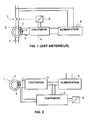
- the differential protection device shown in Figure 1 includes a transformer 1 for detecting differential fault current comprising a circuit magnetic 2 in the shape of a torus and a secondary winding 3 connected to a circuit 4 of treatment.
- the transformer 1 surrounds conductors 5 of a network or a portion of network to protect.
- Processing circuit 4 receives a measurement signal from transformer 1 and commands the opening of a trigger relay 6 to trigger the opening of electrical contacts 7 arranged in series with the conductors 5.
- a supply circuit 8 disposed between power lines and circuit 4 provides the energy needed for measurement and processing of a signal If representative of the differential fault current.
- an excitation circuit is used to excite a winding of the power transformer.
- an excitation circuit 9 is connected to the secondary winding 3 to provide an excitation signal Ie.
- Circuit 9 excitation is also connected to the supply circuit 8 to receive the necessary energy to the excitation of the winding 3. Depending on the type of magnetic circuit this energy can be high and make the protection device too bulky for type devices modular of small dimensions.
- the excitation circuit can supply energy very low excitation even at high frequencies much higher than a frequency nominal of the electrical network to be protected.
- a current transformer according to the invention allows the detection of alternating and direct currents of very high precision and very low values, for example a few milliamps.
- the circuit magnetic transformer has a rectangular cycle with a weak coercive field, of low frequency losses, and good temperature stability.
- the block diagram in Figure 3 represents a differential protection device comprising the supply circuit 8 supplying an excitation circuit 9 to supply a excitation signal Ie to a winding 3 of a detection transformer 1.
- the circuit magnetic 2 of the transformer having particular magnetic characteristics, the electrical energy supplied by the excitation circuit is low and the supply circuit can be reduced.
- the circuit 9 injects into the winding 3 a signal excitation in the form of a triangular current.
- the peak excitation of winding 3 is less than 3.5 Ampere turns at peak value, for protection against differential currents of 30mA. For example, a peak current less than 70 milliamps for a winding of 50 turns. For other protection values, characteristics of the magnetic circuit and excitation values may be different.
- the power supplied for the excitation can then be less than one Watt.
- a saturation detection module 10 detects and processes signal peaks representative of the overshooting of the saturation of the magnetic circuit.
- the module 10 determines time intervals between peaks and provides, for example, a rectangular signal whose duty cycle is dependent on the instants of appearance of the peaks or overshoots of saturation elbows of the magnetic circuit in a first sense then in a second opposite direction.
- the signal supplied by the module 10 is applied to a entry of an integration module 11.
- a module of filter receives an integration signal and provides a filtered signal to a comparison module 13. The filtered signal is then compared to a reference threshold. If the said threshold is exceeded on module 13 controls the trigger relay 6.
- FIGS. 4A to 4D illustrate signals from a differential protection device, comprising a transformer according to an embodiment of the invention.
- Figure 4A represents a curve showing the appearance of a differential fault current Id at a instant t1.
- FIG. 4B represents a curve 15 showing a magnetic field H produced in the magnetic circuit by the excitation current of the winding le and by the current differential fault.
- Limits 16 and 17 show the protrusion of an elbow of saturation of the magnetic circuit.
- the frequency of the triangular signals is preferably much higher than the frequency of a network to be protected, for example a frequency excitation from 300Hz to a few kHz.
- a curve 18 represents peaks representative of exceeding the saturation induction. Such peaks can be detected and processed by a module 10.
- FIG. 4D shows rectangular signals triggered by peaks 18. For proper operation at these frequencies, the magnetization is substantially rectangular to present a change of state magnetic abrupt, and the magnetic field with zero induction is advantageously very low.
- the magnetic circuit is made for example of nanocrystalline or amorphous magnetic material having static characteristics such that the magnetization cycle is substantially rectangular with a coercive field less than 3A / m.
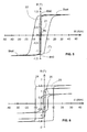
- Figure 5 shows magnetization cycles of a current sensing transformer differential according to one embodiment of the invention.
- Cycle 21 static or low frequency is such that the coercive field Hc allowing the induction to be reduced to 0 Tesla is less than 3 amps per meter (A / m), preferably less than 1.5 A / m.
- Induction at zero field Bh0 and the induction Bsat at saturation of the magnetic circuit are preferably greater than a tesla.
- the rectangular cycle is advantageously with pronounced elbows.
- the rectangular characteristics of the cycle may preferably be such that the ratio of a residual induction or zero field induction on a saturation induction Bsat is greater than 95% for a frequency of 50 Hz.
- the zero induction field is less than 11 A / m and the zero field induction is greater than 1.2 Tesla.
- the gain corresponding to the variation of the magnetic field on the variation in induction is greater than 200%.
- This gain is determined in particular according to the method (CCFR) "Constant Current Flux Reset” standardized in the United States from America under ASTM number A598.
- Figure 6 shows comparative cycles in static or quasi-static between a cycle 23 of a detection transformer according to an embodiment of the invention and of the cycles 24 and 25 for magnetizing toroids measuring the state of the art.
- Cycle 23 has a rectangular shape with a weak coercive field less than 3 A / m and an induction at null field greater than 1 tesla to reduce the excitation energy of the magnetic circuit.
- the cycle 24 has a rectangular cycle but a high coercive field of the order of 10 A / m. In this case a large excitation energy is required to measure a current of differential fault.
- the coercive field is slightly reduced but the shape rounding of the cycle does not allow the principle of excitation to be correctly used for measure a fault current.
- Cycle 23 corresponds to a magnetic material for the measurement of alternating currents at own current and at low frequency. Such a cycle 25 is not not easily usable for excitation devices.
- FIG. 7 shows a curve 26 illustrating the variation of induction of a transformer of detection for a differential protection device according to an embodiment of the invention, defined at 300 Hz according to the CCFR method.
- part 27 of the curve has an induction variation greater than 2 teslas for a field less than 3 A / m.
- the variation induction is advantageously greater than 2.5 teslas.
- a magnetic circuit of a transformer according to an embodiment of the invention has very high frequency response.
- the circuit magnetic of the transformer has a magnetic field of less than 20 Amperes per meter (20 A / m) with zero induction.
- comparative curves illustrate the differences between prior art magnetic circuits and a magnetic circuit according to a mode of realization of the invention.
- Curves 28 and 29 show variations in induction magnetic as a function of a magnetic field respectively at 50 Hz and 400 Hz of a material for a transformer having a cycle according to curve 24 of FIG. 6.
- the high variation in induction indicates a substantially rectangular cycle but for very high field values.
- Such a magnetic material has a coercive field or a very high zero induction field which implies a very high energy consumption excitation.
- Curves 30 and 31 show variations in magnetic induction of a material for a transformer having a cycle according to curve 25 of FIG. 6 respectively at 50Hz and 400 Hz.
- Curves 32 and 33 show variations in magnetic induction as a function of a magnetic field at 50 Hz and 400 Hz respectively of a magnetic circuit of transformer according to an embodiment of the invention.
- Such a transformer accumulates characteristics of a rectangular cycle and a weak coercive or zero induction field.
- a material of the magnetic circuit according to an embodiment of the invention can be of nanocrystalline or amorphous type.
- the material can also be an alloy soft magnetic iron-based, the structure of which consists of more than 50% grains fine crystals with a grain size less than 100nm.
- the magnetic circuit of detection transformer is preferably obtained by heat treatment of a few hundreds of degrees Celsius, under the magnetic field of a torus formed from a ribbon wound.
- the magnetic circuit is produced by a strip of magnetic material having a thickness of less than 30 ⁇ m.
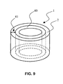
- FIG. 9 shows a current detection transformer comprising a support 40 to hold the magnetic material.
- a support 40 to hold the magnetic material.
- magnetic material is rolled up in strips on the support 40, the roll of strips forming a magnetic circuit 2 thickness 41 less than a millimeter (mm).
- the thickness of the circuit magnetic wound is 0.5 millimeter.
- the support 40 is preferably made of non-material magnetic. It gives the magnetic circuit good mechanical strength even if the amount of magnetic material is reduced.
- the magnetic circuit can also advantageously be produced by one or more washers of magnetic material as defined above. These washers can in particular be carried out by punching or by cutting.
- the device described above is an exemplary embodiment. Other device diagrams may be suitable for implementing the invention.
Landscapes
- Physics & Mathematics (AREA)
- General Physics & Mathematics (AREA)
- Engineering & Computer Science (AREA)
- Power Engineering (AREA)
- Protection Of Transformers (AREA)
- Emergency Protection Circuit Devices (AREA)
- Measuring Instrument Details And Bridges, And Automatic Balancing Devices (AREA)
- Investigating Or Analyzing Materials By The Use Of Magnetic Means (AREA)
- Transmission And Conversion Of Sensor Element Output (AREA)
- Supply Devices, Intensifiers, Converters, And Telemotors (AREA)
- Bidet-Like Cleaning Device And Other Flush Toilet Accessories (AREA)
- Regulation Of General Use Transformers (AREA)
Abstract
Description
- un circuit d'excitation connecté à au moins un enroulement secondaire dudit transformateur de détection pour appliquer des signaux d'excitation,
- un circuit de traitement connecté à l'enroulement secondaire, et
- un circuit d'alimentation connecté au circuit d'excitation et au circuit de traitement.
- un transformateur de détection de courant de défaut différentiel en forme de tore comportant au moins un enroulement secondaire,
- un circuit d'excitation connecté audit au moins un enroulement secondaire dudit transformateur de détection pour appliquer des signaux d'excitation,
- un circuit de traitement connecté à l'enroulement secondaire, et
- un circuit d'alimentation connecté au circuit d'excitation et au circuit de traitement, le transformateur de détection de courant est un transformateur tel que défini ci-dessus.
- la figure 1 représente un schéma d'un dispositif de protection différentielle de l'art antérieur;
- la figure 2 représente un schéma bloc d'un dispositif de protection pouvant comporter un transformateur de détection selon un mode de réalisation de l'invention ;
- la figure 3 représente un schéma bloc détaillé d'un dispositif de protection pouvant comporter un transformateur de détection selon un mode de réalisation de l'invention ;
- les figures 4A à 4D illustrent des signaux d'un dispositif de protection pouvant comporter un transformateur de détection selon un mode de réalisation de l'invention ;
- le figure 5 représente des cycles de magnétisation d'un transformateur de détection de courant de défaut différentiel selon un mode de réalisation de l'invention ;
- la figure 6 représente des cycles de magnétisation d'un transformateur de détection de courant de défaut différentiel selon un mode de réalisation de l'invention et de transformateurs de l'art antérieur ;
- la figure 7 représente une courbe normalisée de l'induction en fonction du champ magnétique d'un transformateur de détection selon un mode de réalisation de l'invention ;
- la figure 8 représente des courbes normalisées de l'induction en fonction du champ magnétique d'un transformateur de détection de courant de défaut différentiel selon un mode de réalisation de l'invention et de transformateurs de l'art antérieur ; et
- la figure 9 représente un circuit magnétique d'un transformateur selon un mode de réalisation de l'invention comportant un support.
Claims (16)
- Transformateur de détection de courant de défaut différentiel en forme de tore pour dispositif de protection différentielle sensible à un courant de défaut différentiel alternatif, continu ou périodique, ledit dispositif de protection comportant:un circuit d'excitation (9) connecté à au moins un enroulement secondaire (3) dudit transformateur de détection pour appliquer des signaux d'excitation (Ie),un circuit de traitement (4) connecté à l'enroulement secondaire, etun circuit d'alimentation (8) connecté au circuit d'excitation et au circuit de traitement, transformateur de détection caractérisé en ce qu'il comporte un circuit magnétique réalisé en matériau magnétique à base de fer ayant des cristaux de grosseur inférieure à 100nm et des caractéristiques magnétiques en statique ou en basse fréquence telles que un cycle (21, 23) de magnétisation est sensiblement rectangulaire et un champ coercitif (Hc) est inférieur à 3 Ampères par mètre.
- Transformateur de détection de courant selon la revendication 1 caractérisé en ce que le cycle (21, 23) rectangulaire est tel que le rapport entre une induction à champ nul (Bh0) sur une induction de saturation (Bsat) est supérieur à 0,95.
- Transformateur de détection de courant selon l'une des revendications 1 ou 2 caractérisé en ce que le champ coercitif (Hc) est inférieur à 1,5 Ampères par mètre en statique ou en basse fréquence.
- Transformateur de détection de courant selon l'une quelconque des revendications 1 à 3 caractérisé en ce que le circuit magnétique du transformateur a un rapport champ coercitif sur induction à champ nul tel que le champ coercitif est inférieur (Hc) à 3A/m pour une induction à champ nul (Bh0) supérieure à 1 Tesla.
- Transformateur de détection de courant selon l'une quelconque des revendications 1 à 4 caractérisé en ce que la variation de l'induction du circuit magnétique du transformateur, en statique ou à une fréquence inférieure à 400Hz, est supérieure à 2 Teslas pour un champ magnétique inférieur à 3 Ampères par mètre (3 A/m).
- Transformateur de détection de courant selon la revendication 5 caractérisé en ce que la variation de l'induction du circuit magnétique du transformateur, en statique ou à une fréquence inférieure à 400Hz, est supérieure à 2,4 Teslas pour un champ magnétique inférieur à 2,5 Ampères par mètre (2,5 A/m).
- Transformateur de détection de courant selon l'une quelconque des revendications 1 à 6 caractérisé en ce que le circuit magnétique du transformateur a un champ magnétique inférieur à 20 Ampères par mètre (20 A/m) à induction nulle à une fréquence de trois kilohertz (kHz).
- Transformateur de détection de courant selon l'une quelconque des revendications 1 à 7 caractérisé en ce que le circuit magnétique est obtenu par un traitement thermique sous un champ magnétique.
- Transformateur de détection de courant selon l'une quelconque des revendications 1 à 8 caractérisé en ce que le matériau du circuit magnétique comporte plus de 50% de grains à fins cristaux ayant une grosseur de grains inférieure à 100nm.
- Transformateur de détection de courant selon l'une quelconque des revendications 1 à 9 caractérisé en ce que le matériau du circuit magnétique est réalisé par des bandes de matériaux ayant une épaisseur inférieure à 30 micromètres (µm).
- Transformateur de détection de courant selon l'une quelconque des revendications 1 à 10 caractérisé en ce qu'il comporte un support (40) pour maintenir le matériau magnétique.
- Transformateur de détection de courant selon la revendication 11 caractérisé en ce que le matériau magnétique est enroulé en bandes sur le support (40), les bandes formant un circuit magnétique (2) d'épaisseur (41) inférieure à un millimètre.
- Transformateur de détection de courant selon l'une quelconque des revendications 1 à 10 caractérisé en ce que le circuit magnétique est constitué par au moins une rondelle de matériau magnétique.
- Dispositif de protection différentielle sensible à un courant de défaut différentiel alternatif, continu ou périodique, comportant:caractérisé en ce que le transformateur de détection de courant est un transformateur selon l'une quelconque des revendications 1 à 11.un transformateur (1) de détection de courant de défaut différentiel en forme de tore comportant au moins un enroulement (3) secondaire,un circuit d'excitation (9) connecté audit au moins un enroulement secondaire dudit transformateur de détection pour appliquer des signaux d'excitation,un circuit (4) de traitement connecté à l'enroulement secondaire, etun circuit (8) d'alimentation connecté au circuit d'excitation et au circuit de traitement,
- Dispositif selon la revendication 14 caractérisé en ce que le circuit (9) d'excitation comporte des moyens pour injecter dans l'enroulement (3) secondaire un courant (Ie, 15) de forme triangulaire, une excitation correspondant à une amplitude de crête dudit courant (Ie, 15) et à un nombre de spires de l'enroulement (3) étant inférieure à 3,5 ampère-tours.
- Dispositif selon l'une des revendications 14 ou 15 caractérisé en ce que le circuit d'alimentation fournit au circuit d'excitation et à l'enroulement secondaire une puissance inférieure à 1 Watt.
Applications Claiming Priority (2)
| Application Number | Priority Date | Filing Date | Title |
|---|---|---|---|
| FR0106674A FR2824951B1 (fr) | 2001-05-21 | 2001-05-21 | Transformateur de detection pour dispositif de protection differentielle et dispositif de protection comportant un tel transformateur |
| FR0106674 | 2001-05-21 |
Publications (2)
| Publication Number | Publication Date |
|---|---|
| EP1260821A1 true EP1260821A1 (fr) | 2002-11-27 |
| EP1260821B1 EP1260821B1 (fr) | 2005-11-30 |
Family
ID=8863499
Family Applications (1)
| Application Number | Title | Priority Date | Filing Date |
|---|---|---|---|
| EP02354072A Expired - Lifetime EP1260821B1 (fr) | 2001-05-21 | 2002-04-29 | Transformateur de détection pour dispositif de protection différentielle et dispositif de protection comportant un tel transformateur |
Country Status (7)
| Country | Link |
|---|---|
| EP (1) | EP1260821B1 (fr) |
| CN (1) | CN1241216C (fr) |
| AT (1) | ATE311607T1 (fr) |
| DE (1) | DE60207632T2 (fr) |
| ES (1) | ES2252413T3 (fr) |
| FR (1) | FR2824951B1 (fr) |
| ZA (1) | ZA200203953B (fr) |
Cited By (1)
| Publication number | Priority date | Publication date | Assignee | Title |
|---|---|---|---|---|
| CN102937682A (zh) * | 2012-11-29 | 2013-02-20 | 东莞市拓诚实业有限公司 | 一种漏电保护器检测设备及检测方法 |
Families Citing this family (9)
| Publication number | Priority date | Publication date | Assignee | Title |
|---|---|---|---|---|
| FR2862423B1 (fr) * | 2003-11-18 | 2005-12-30 | Schneider Electric Ind Sas | Dispositif et procede de protection differentielle et appareil electrique comportant un tel dispositif |
| IT1392716B1 (it) * | 2009-01-13 | 2012-03-16 | Seneca S R L | Metodo di misura di una corrente elettrica |
| CN102881437A (zh) * | 2011-07-12 | 2013-01-16 | 三信国际电器上海有限公司 | 一种用于检测剩余电流的电流互感器和剩余电流保护装置 |
| DE102013009587A1 (de) * | 2012-06-14 | 2013-12-19 | Robert Bosch Gmbh | Gerät und Verfahren zur Feststellung der Sättigung eines Magnetkerns eines Transformators |
| FR3050081B1 (fr) * | 2016-04-12 | 2018-03-23 | Schneider Electric Industries Sas | Dispositif de detection d'un courant de defaut |
| CN113809716B (zh) * | 2021-09-25 | 2023-09-15 | 浙江巨磁智能技术有限公司 | 一种纯硬件化实现的b型漏电保护方法 |
| DE102022129457B4 (de) * | 2022-11-08 | 2024-05-29 | Bender Gmbh & Co. Kg | Elektrische Schaltungsanordnung und Verfahren zur galvanisch getrennten, allstromsensitiven Differenzstrom-Messung |
| FR3147376B1 (fr) * | 2023-03-29 | 2025-02-28 | Chauvin Arnoux | Procédé de mesure et Ohmmètre de boucle mono-tore à compensation de flux de fuite DC |
| FR3147377B1 (fr) * | 2023-03-29 | 2025-02-28 | Chauvin Arnoux | Procédé de mesure et Ohmmètre de boucle mono-tore à compensation de flux de fuite AC |
Citations (2)
| Publication number | Priority date | Publication date | Assignee | Title |
|---|---|---|---|---|
| JPH01235213A (ja) * | 1988-03-15 | 1989-09-20 | Hitachi Metals Ltd | 磁気センサー及び電流センサー並びにこれを用いた装置 |
| EP0651258A2 (fr) * | 1993-11-02 | 1995-05-03 | Sumitomo Special Metal Co., Ltd. | Capteur de courant continu |
Family Cites Families (5)
| Publication number | Priority date | Publication date | Assignee | Title |
|---|---|---|---|---|
| US4529931A (en) * | 1983-04-07 | 1985-07-16 | Ford Motor Company | Single-coil current measuring circuit |
| US4881989A (en) * | 1986-12-15 | 1989-11-21 | Hitachi Metals, Ltd. | Fe-base soft magnetic alloy and method of producing same |
| JPH03218475A (ja) * | 1989-11-06 | 1991-09-26 | Nkk Corp | 電流計測方法及びその装置 |
| FR2733374B1 (fr) * | 1995-04-18 | 1997-06-06 | Schneider Electric Sa | Dispositif de protection differentielle sensible aux courants pulses |
| FR2774822B1 (fr) * | 1998-02-11 | 2000-03-17 | Schneider Electric Ind Sa | Dispositif de protection differentielle |
-
2001
- 2001-05-21 FR FR0106674A patent/FR2824951B1/fr not_active Expired - Fee Related
-
2002
- 2002-04-29 AT AT02354072T patent/ATE311607T1/de not_active IP Right Cessation
- 2002-04-29 DE DE60207632T patent/DE60207632T2/de not_active Expired - Lifetime
- 2002-04-29 ES ES02354072T patent/ES2252413T3/es not_active Expired - Lifetime
- 2002-04-29 EP EP02354072A patent/EP1260821B1/fr not_active Expired - Lifetime
- 2002-05-15 CN CN02119801.2A patent/CN1241216C/zh not_active Expired - Fee Related
- 2002-05-17 ZA ZA200203953A patent/ZA200203953B/xx unknown
Patent Citations (2)
| Publication number | Priority date | Publication date | Assignee | Title |
|---|---|---|---|---|
| JPH01235213A (ja) * | 1988-03-15 | 1989-09-20 | Hitachi Metals Ltd | 磁気センサー及び電流センサー並びにこれを用いた装置 |
| EP0651258A2 (fr) * | 1993-11-02 | 1995-05-03 | Sumitomo Special Metal Co., Ltd. | Capteur de courant continu |
Non-Patent Citations (1)
| Title |
|---|
| PATENT ABSTRACTS OF JAPAN vol. 013, no. 564 (E - 860) 14 December 1989 (1989-12-14) * |
Cited By (1)
| Publication number | Priority date | Publication date | Assignee | Title |
|---|---|---|---|---|
| CN102937682A (zh) * | 2012-11-29 | 2013-02-20 | 东莞市拓诚实业有限公司 | 一种漏电保护器检测设备及检测方法 |
Also Published As
| Publication number | Publication date |
|---|---|
| EP1260821B1 (fr) | 2005-11-30 |
| DE60207632T2 (de) | 2006-07-06 |
| DE60207632D1 (de) | 2006-01-05 |
| ZA200203953B (en) | 2002-11-21 |
| ATE311607T1 (de) | 2005-12-15 |
| FR2824951A1 (fr) | 2002-11-22 |
| CN1241216C (zh) | 2006-02-08 |
| CN1387213A (zh) | 2002-12-25 |
| ES2252413T3 (es) | 2006-05-16 |
| FR2824951B1 (fr) | 2003-07-25 |
Similar Documents
| Publication | Publication Date | Title |
|---|---|---|
| EP1805772B1 (fr) | Tore nanocristallin pour capteur de courant, compteurs d'energie a simple et a double etage et sondes de courant les incorporant | |
| EP0704867B1 (fr) | Dispositif de déclenchement comportant au moins un transformateur de courant | |
| EP0391812B1 (fr) | Système de controle d'isolement d'un réseau à courant continu | |
| EP1260821B1 (fr) | Transformateur de détection pour dispositif de protection différentielle et dispositif de protection comportant un tel transformateur | |
| EP3232526B1 (fr) | Dispositif de détection d'un courant de défaut | |
| FR2703467A1 (fr) | Capteur de courant à effet Hall à flux nul destiné en particulier aux véhicules automobiles et scooters électriques. | |
| FR3060757A1 (fr) | Capteur de courant a vanne de flux | |
| EP3561523A1 (fr) | Transformateur de courant testable et appareil electrique comportant des moyens de test d'un tel transformateur de courant | |
| US6653850B2 (en) | Surface passivation method and arrangement for measuring the lifetime of minority carriers in semiconductors | |
| EP1533880B1 (fr) | Dispositif et procédé de protection différentielle et appareil électrique comportant un tel dispositif | |
| EP0841670A1 (fr) | Transformateur de courant, déclencheur et disjoncteur comportant un tel transformateur | |
| EP0443342A1 (fr) | Procédé de contrôle du transfert d'énergie dans un convertisseur statique; convertisseur statique d'énergie pour sa mise en oeuvre et alimentation électrique utilisant un tel convertisseur | |
| EP1217707A1 (fr) | Dispositif de détermination du courant primaire d'un transformateur de courant comportant des moyens de correction de saturation | |
| Kunst et al. | The influence of deposition temperature and annealing temperature on the optoelectronic properties of hydrogenated amorphous silicon films | |
| FR3147040A1 (fr) | Circuit de protection à courant résiduel pour la détection d'un courant continu | |
| FR2694408A1 (fr) | Dispositif détecteur de défauts sur un réseau de distribution d'énergie électrique aérien. | |
| EP0821830B1 (fr) | Declencheur par courant de defaut sensible aux courants pulses | |
| EP0783110B1 (fr) | Capteur de courant à large gamme de fonctionnement | |
| FR2595478A1 (fr) | Element de commutation de lumiere magneto-optique | |
| Mangaiyarkarasi et al. | Controlled shift in emission wavelength from patterned porous silicon using focused ion beam irradiation | |
| JP2000002738A (ja) | 直流漏電検出装置 | |
| EP0813283B1 (fr) | Dispositif de protection différentielle immunisé contre les déclenchements intempestifs | |
| Gulyaev et al. | Efficiency of the terahertz spin-injection emitter | |
| JP2005127940A (ja) | 超伝導厚膜の臨界電流密度及び電流・電圧特性の測定方法、及び装置 | |
| EP0522907A1 (fr) | Contrôle d'un vitrage chauffant |
Legal Events
| Date | Code | Title | Description |
|---|---|---|---|
| PUAI | Public reference made under article 153(3) epc to a published international application that has entered the european phase |
Free format text: ORIGINAL CODE: 0009012 |
|
| AK | Designated contracting states |
Kind code of ref document: A1 Designated state(s): AT BE CH CY DE DK ES FI FR GB GR IE IT LI LU MC NL PT SE TR |
|
| AX | Request for extension of the european patent |
Free format text: AL;LT;LV;MK;RO;SI |
|
| 17P | Request for examination filed |
Effective date: 20021207 |
|
| 17Q | First examination report despatched |
Effective date: 20030425 |
|
| AKX | Designation fees paid |
Designated state(s): AT BE CH CY DE DK ES FI FR GB GR IE IT LI LU MC NL PT SE TR |
|
| GRAP | Despatch of communication of intention to grant a patent |
Free format text: ORIGINAL CODE: EPIDOSNIGR1 |
|
| GRAS | Grant fee paid |
Free format text: ORIGINAL CODE: EPIDOSNIGR3 |
|
| GRAA | (expected) grant |
Free format text: ORIGINAL CODE: 0009210 |
|
| AK | Designated contracting states |
Kind code of ref document: B1 Designated state(s): AT BE CH CY DE DK ES FI FR GB GR IE IT LI LU MC NL PT SE TR |
|
| PG25 | Lapsed in a contracting state [announced via postgrant information from national office to epo] |
Ref country code: FI Free format text: LAPSE BECAUSE OF FAILURE TO SUBMIT A TRANSLATION OF THE DESCRIPTION OR TO PAY THE FEE WITHIN THE PRESCRIBED TIME-LIMIT Effective date: 20051130 Ref country code: AT Free format text: LAPSE BECAUSE OF FAILURE TO SUBMIT A TRANSLATION OF THE DESCRIPTION OR TO PAY THE FEE WITHIN THE PRESCRIBED TIME-LIMIT Effective date: 20051130 Ref country code: IE Free format text: LAPSE BECAUSE OF FAILURE TO SUBMIT A TRANSLATION OF THE DESCRIPTION OR TO PAY THE FEE WITHIN THE PRESCRIBED TIME-LIMIT Effective date: 20051130 |
|
| REG | Reference to a national code |
Ref country code: GB Ref legal event code: FG4D Free format text: NOT ENGLISH Ref country code: CH Ref legal event code: EP |
|
| REG | Reference to a national code |
Ref country code: IE Ref legal event code: FG4D Free format text: LANGUAGE OF EP DOCUMENT: FRENCH |
|
| REF | Corresponds to: |
Ref document number: 60207632 Country of ref document: DE Date of ref document: 20060105 Kind code of ref document: P |
|
| GBT | Gb: translation of ep patent filed (gb section 77(6)(a)/1977) |
Effective date: 20060118 |
|
| PG25 | Lapsed in a contracting state [announced via postgrant information from national office to epo] |
Ref country code: DK Free format text: LAPSE BECAUSE OF FAILURE TO SUBMIT A TRANSLATION OF THE DESCRIPTION OR TO PAY THE FEE WITHIN THE PRESCRIBED TIME-LIMIT Effective date: 20060228 Ref country code: GR Free format text: LAPSE BECAUSE OF FAILURE TO SUBMIT A TRANSLATION OF THE DESCRIPTION OR TO PAY THE FEE WITHIN THE PRESCRIBED TIME-LIMIT Effective date: 20060228 Ref country code: SE Free format text: LAPSE BECAUSE OF FAILURE TO SUBMIT A TRANSLATION OF THE DESCRIPTION OR TO PAY THE FEE WITHIN THE PRESCRIBED TIME-LIMIT Effective date: 20060228 |
|
| PG25 | Lapsed in a contracting state [announced via postgrant information from national office to epo] |
Ref country code: BE Free format text: LAPSE BECAUSE OF NON-PAYMENT OF DUE FEES Effective date: 20060430 Ref country code: MC Free format text: LAPSE BECAUSE OF NON-PAYMENT OF DUE FEES Effective date: 20060430 Ref country code: CH Free format text: LAPSE BECAUSE OF NON-PAYMENT OF DUE FEES Effective date: 20060430 Ref country code: LI Free format text: LAPSE BECAUSE OF NON-PAYMENT OF DUE FEES Effective date: 20060430 |
|
| PG25 | Lapsed in a contracting state [announced via postgrant information from national office to epo] |
Ref country code: PT Free format text: LAPSE BECAUSE OF FAILURE TO SUBMIT A TRANSLATION OF THE DESCRIPTION OR TO PAY THE FEE WITHIN THE PRESCRIBED TIME-LIMIT Effective date: 20060502 |
|
| REG | Reference to a national code |
Ref country code: ES Ref legal event code: FG2A Ref document number: 2252413 Country of ref document: ES Kind code of ref document: T3 |
|
| REG | Reference to a national code |
Ref country code: IE Ref legal event code: FD4D |
|
| PLBE | No opposition filed within time limit |
Free format text: ORIGINAL CODE: 0009261 |
|
| STAA | Information on the status of an ep patent application or granted ep patent |
Free format text: STATUS: NO OPPOSITION FILED WITHIN TIME LIMIT |
|
| 26N | No opposition filed |
Effective date: 20060831 |
|
| REG | Reference to a national code |
Ref country code: CH Ref legal event code: PL |
|
| BERE | Be: lapsed |
Owner name: SCHNEIDER ELECTRIC INDUSTRIES SAS Effective date: 20060430 |
|
| PG25 | Lapsed in a contracting state [announced via postgrant information from national office to epo] |
Ref country code: LU Free format text: LAPSE BECAUSE OF NON-PAYMENT OF DUE FEES Effective date: 20060429 Ref country code: TR Free format text: LAPSE BECAUSE OF FAILURE TO SUBMIT A TRANSLATION OF THE DESCRIPTION OR TO PAY THE FEE WITHIN THE PRESCRIBED TIME-LIMIT Effective date: 20051130 |
|
| PG25 | Lapsed in a contracting state [announced via postgrant information from national office to epo] |
Ref country code: CY Free format text: LAPSE BECAUSE OF FAILURE TO SUBMIT A TRANSLATION OF THE DESCRIPTION OR TO PAY THE FEE WITHIN THE PRESCRIBED TIME-LIMIT Effective date: 20051130 |
|
| PGFP | Annual fee paid to national office [announced via postgrant information from national office to epo] |
Ref country code: ES Payment date: 20140311 Year of fee payment: 13 |
|
| PGFP | Annual fee paid to national office [announced via postgrant information from national office to epo] |
Ref country code: GB Payment date: 20140423 Year of fee payment: 13 |
|
| PGFP | Annual fee paid to national office [announced via postgrant information from national office to epo] |
Ref country code: IT Payment date: 20140414 Year of fee payment: 13 Ref country code: NL Payment date: 20140410 Year of fee payment: 13 Ref country code: DE Payment date: 20140408 Year of fee payment: 13 Ref country code: FR Payment date: 20140410 Year of fee payment: 13 |
|
| REG | Reference to a national code |
Ref country code: DE Ref legal event code: R119 Ref document number: 60207632 Country of ref document: DE |
|
| GBPC | Gb: european patent ceased through non-payment of renewal fee |
Effective date: 20150429 |
|
| REG | Reference to a national code |
Ref country code: NL Ref legal event code: MM Effective date: 20150501 |
|
| PG25 | Lapsed in a contracting state [announced via postgrant information from national office to epo] |
Ref country code: IT Free format text: LAPSE BECAUSE OF NON-PAYMENT OF DUE FEES Effective date: 20150429 Ref country code: GB Free format text: LAPSE BECAUSE OF NON-PAYMENT OF DUE FEES Effective date: 20150429 Ref country code: DE Free format text: LAPSE BECAUSE OF NON-PAYMENT OF DUE FEES Effective date: 20151103 |
|
| REG | Reference to a national code |
Ref country code: FR Ref legal event code: ST Effective date: 20151231 |
|
| PG25 | Lapsed in a contracting state [announced via postgrant information from national office to epo] |
Ref country code: FR Free format text: LAPSE BECAUSE OF NON-PAYMENT OF DUE FEES Effective date: 20150430 |
|
| PG25 | Lapsed in a contracting state [announced via postgrant information from national office to epo] |
Ref country code: NL Free format text: LAPSE BECAUSE OF NON-PAYMENT OF DUE FEES Effective date: 20150501 |
|
| REG | Reference to a national code |
Ref country code: ES Ref legal event code: FD2A Effective date: 20160526 |
|
| PG25 | Lapsed in a contracting state [announced via postgrant information from national office to epo] |
Ref country code: ES Free format text: LAPSE BECAUSE OF NON-PAYMENT OF DUE FEES Effective date: 20150430 |