EP1261007A1 - Sicherheitsauslöser für entfernbaren Schutzschalter - Google Patents
Sicherheitsauslöser für entfernbaren Schutzschalter Download PDFInfo
- Publication number
- EP1261007A1 EP1261007A1 EP02011243A EP02011243A EP1261007A1 EP 1261007 A1 EP1261007 A1 EP 1261007A1 EP 02011243 A EP02011243 A EP 02011243A EP 02011243 A EP02011243 A EP 02011243A EP 1261007 A1 EP1261007 A1 EP 1261007A1
- Authority
- EP
- European Patent Office
- Prior art keywords
- bar
- actuation
- circuit breaker
- contact
- cavity
- Prior art date
- Legal status (The legal status is an assumption and is not a legal conclusion. Google has not performed a legal analysis and makes no representation as to the accuracy of the status listed.)
- Granted
Links
- 238000009434 installation Methods 0.000 claims description 22
- 230000009471 action Effects 0.000 claims description 4
- 230000000284 resting effect Effects 0.000 claims description 4
- 230000008901 benefit Effects 0.000 description 3
- 239000004020 conductor Substances 0.000 description 2
- 238000004519 manufacturing process Methods 0.000 description 2
- 238000000034 method Methods 0.000 description 2
- 230000008569 process Effects 0.000 description 2
- 239000000463 material Substances 0.000 description 1
- 230000007246 mechanism Effects 0.000 description 1
- 230000004048 modification Effects 0.000 description 1
- 238000012986 modification Methods 0.000 description 1
Images


Classifications
-
- H—ELECTRICITY
- H01—ELECTRIC ELEMENTS
- H01H—ELECTRIC SWITCHES; RELAYS; SELECTORS; EMERGENCY PROTECTIVE DEVICES
- H01H71/00—Details of the protective switches or relays covered by groups H01H73/00 - H01H83/00
- H01H71/10—Operating or release mechanisms
- H01H71/12—Automatic release mechanisms with or without manual release
- H01H71/126—Automatic release mechanisms with or without manual release actuated by dismounting of circuit breaker or removal of part of circuit breaker
-
- H—ELECTRICITY
- H01—ELECTRIC ELEMENTS
- H01H—ELECTRIC SWITCHES; RELAYS; SELECTORS; EMERGENCY PROTECTIVE DEVICES
- H01H11/00—Apparatus or processes specially adapted for the manufacture of electric switches
- H01H11/0006—Apparatus or processes specially adapted for the manufacture of electric switches for converting electric switches
Definitions
- the present invention relates to a safety release device for removable circuit breakers.
- Enclosed circuit breakers and their accessories can be installed both in a fixed manner and in a removable manner.
- the unit In fixed installation, the unit is fastened to a support and is connected to the conductors by means of the appropriately provided terminals, in a per se known manner, and in this installation no provisions are made for frequent and rapid disassembly of the unit.
- a removable installation is generally achieved by installing receptacles on the connections of the circuit breaker.
- the receptacles provide the electrical connection with fixed bases installed in the electrical panels.
- circuit breakers are usually provided with appropriate mechanical systems adapted to open the contacts when the operator removes the unit while the contacts are closed.
- the safety systems known in the art are either constituted by accessories, to be applied to the unit when it is installed in a removable manner, or are constituted by mechanisms included within the unit but that can be activated by opening the unit.
- the aim of the present invention is to provide a safety release device for removable circuit breakers that is more functional than the devices of the cited prior art.
- An object of the invention is to provide a safety release device for removable circuit breakers that can be switched easily and rapidly depending on whether the unit is installed in a fixed or removable manner.
- a further object of the invention is to provide a safety release device for removable circuit breakers that is constructively simple and economic from the point of view of production.
- a further object is to provide a safety release device for removable circuit breakers that is reliable.
- the safety release device is particularly useful in a circuit breaker, generally designated by the reference numeral 1, which can be installed both in a fixed manner and in a removable manner.
- the circuit breaker 1 is fixed, for example by means of standard guides, in a rather removable manner to a support and is connected to the conductors by means of the appropriately provided terminals, in a per se known manner.
- receptacles are provided on the connections of the circuit breaker.
- the receptacles provide electrical connection to fixed bases installed in the electrical panels.
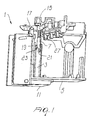
- the safety release device comprises a cylindrical body 3 associated with a body 5 of the circuit breaker and adapted to receive an actuation bar 7, which can slide within the cylindrical body 3.
- the actuation bar 7 has an actuation end 9 protruding out of the circuit breaker body 5 through an opening that connects the inside of the cylindrical body to the outside of the circuit breaker body, at the side 11 that faces the supporting surface, not shown in the figures, to which the circuit breaker body is applied.
- the actuation bar 7 has an actuation end provided with a connecting means, a hook 15 in the specific case, which is operatively connected to a lever 17 acting on the moving contact, not shown, of the circuit breaker so as to define at least two positions: a closed-contact position, shown in Figure 1, and an open-contact position, shown in Figure 2.
- the actuation bar 7 can slide within the cylindrical body 3 in contrast with an elastic means, which in the specific case is constituted by a helical spring 27 which is coaxial to the bar and has an end in contact with a fixed member of the circuit breaker body and another end in contact with a step of the actuation bar formed, in the specific case, by a recessed region of the bar.
- an elastic means which in the specific case is constituted by a helical spring 27 which is coaxial to the bar and has an end in contact with a fixed member of the circuit breaker body and another end in contact with a step of the actuation bar formed, in the specific case, by a recessed region of the bar.
- the actuation bar 7 has a tooth 19 that can selectively engage a longitudinal slot 21 or an edge 23, through the rotation of the bar 7 about its own axis.
- the longitudinal slot 21 and the edge 23 are formed in the cylindrical body 3.
- the bar 7 will be turned until the tooth 19 is located at the slot 21, by acting on the actuation end 9 of the bar 7, for example by means of a tool such as a screwdriver.
- the bar can slide freely outward, pushed by the spring 27, and acts on the lever 17 by means of the hook 15, thereby opening the contact.
- the safety device may be switched from the fixed-installation condition to the removable one, and vice versa, in a very simple and rapid manner: it is in fact sufficient to act on the head of the bar with a screwdriver, or other suitable tool, in order to turn the bar into the intended position.
- FIGS 4 to 9 illustrate a circuit breaker, generally designated by the reference numeral 101, which can be installed both in a fixed manner and in a removable manner and is provided with a safety device according to a further aspect of the invention.
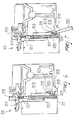
- the safety release device comprises an actuation bar 107 which can slide inside an elongated cavity 103 provided in the body 105 of the circuit breaker.
- the actuation bar 107 has an actuation end 109 which is accessible from the outside of the circuit breaker body 105 through an opening 129 that connects the cavity 103 to the outside of the circuit breaker body, at the side 111 that faces the supporting surface 155, to which the circuit breaker body is applied.
- the actuation bar 107 has an actuation end provided with a connecting means, a hook 115 in the specific case, which is operatively connected to a lever 117 acting on the moving contact, not shown, of the circuit breaker so as to define at least two positions: a closed-contact position, shown in Figures 4, 6, 7, and 9, and an open-contact position, shown in Figure 8.
- the actuation bar 107 can slide within the cavity 103 in contrast with an elastic means, which in the specific case is constituted by a helical spring 127 which is coaxial to the bar and has an end in contact with a fixed member of the circuit breaker body and another end in contact with a step of the actuation bar formed, in the specific case, by a recessed region of the bar.
- an elastic means which in the specific case is constituted by a helical spring 127 which is coaxial to the bar and has an end in contact with a fixed member of the circuit breaker body and another end in contact with a step of the actuation bar formed, in the specific case, by a recessed region of the bar.
- the actuation bar 107 has a tooth 119, provided at the tip of a blade 120, that can selectively engage an edge 123 provided on the wall of the cavity 103.
- the bar 107 should be extracted partially from the cavity by acting with the tip 130 of a screw driver, or any other suitable tool, on the elastic blade 120 in order to disengage the tooth 119 from the edge 123, as visible in Figure 7.
- the bar 107 can slide freely outwards, pushed by the spring 127, and acts on the lever 117 by means of the hook 115, thereby opening the contact.
- the safety device may be switched from the removable condition back to the fixed-installation condition, in a very simple and rapid manner, by simply pushing the head 109 of the bar 107 inside the cavity 103, possibly with the aid of the tip 130 of a tool such as a screwdriver, until the tooth 119 engages the edge 123, thereby locking the bar 107 into the fixed installation condition.
- the bar 207 can slide inside an elongated cavity 203 provided in the body 205 of the circuit breaker.
- the actuation bar 207 has an actuation end 209 which is accessible from the outside of the circuit breaker body 205 through an opening 229 that connects the cavity 203 to the outside of the circuit breaker body, at the side 211 that faces the supporting surface 255, to which the circuit breaker body is applied.
- the actuation bar 207 has an actuation end provided with a connecting means, a hook 215 in the specific case, which is operatively connected to a lever 217 acting on the moving contact, not shown, of the circuit breaker so as to define a closed-contact position and an open-contact position, as described above.
- the actuation bar 207 can slide within the cavity 203 in contrast with an elastic means, which in the specific case is constituted by a helical spring 227 which is coaxial to the bar and has an end in contact with a fixed member of the circuit breaker body and another end in contact with a step of the actuation bar formed, in the specific case, by a recessed region of the bar.
- an elastic means which in the specific case is constituted by a helical spring 227 which is coaxial to the bar and has an end in contact with a fixed member of the circuit breaker body and another end in contact with a step of the actuation bar formed, in the specific case, by a recessed region of the bar.
- the actuation bar 207 has a tooth 219, provided at a median portion of a blade 220, that can selectively engage an edge 223 provided on the wall of the cavity 203.
- the bar 207 When the bar 207 has the tooth 219 engaged with the edge 223, the bar 207 is prevented from sliding outwards, despite the action of the contrast spring 227, which biases the bar 207 outwards. In such condition, the hook 215 keeps the lever 217 in the closed-contact position and the circuit breaker is therefore in a fixed-installation condition.
- the bar 207 should be extracted partially from the cavity by acting with the tip 130 of a screw driver, or any other suitable tool, on the elastic blade 220 in order to disengage the tooth 219 from the edge 223, as visible in Figure 10.
- the bar 207 can slide freely outwards, pushed by the spring 227, and acts on the lever 217 by means of the hook 215, thereby opening the contact.
- the safety device may be switched from the removable condition back to the fixed-installation condition, in a very simple and rapid manner, by simply pushing the head 209 of the bar 207 inside the cavity 203, possibly with the aid of the tip 130 of a tool such as a screwdriver, until the tooth 219 engages the edge 223, thereby locking the bar 207 into the fixed installation condition.
- the invention achieves the intended aim and objects, providing a safety device that can be switched easily and rapidly depending on whether the unit has to be installed in a fixed or removable manner.
- the device according to the invention is extremely simple from the constructive point of view, fully to the advantage of low manufacturing costs and operating reliability.
- Another functional advantage of the device is the fact that it is not necessary to open the unit in order to activate or deactivate the safety function.
- the materials used, as well as the dimensions, may of course be any according to requirements and to the state of the art.
Landscapes
- Breakers (AREA)
- Switch Cases, Indication, And Locking (AREA)
- Push-Button Switches (AREA)
- Driving Mechanisms And Operating Circuits Of Arc-Extinguishing High-Tension Switches (AREA)
- Fuses (AREA)
Applications Claiming Priority (2)
| Application Number | Priority Date | Filing Date | Title |
|---|---|---|---|
| ITMI20011069 | 2001-05-22 | ||
| IT2001MI001069A ITMI20011069A1 (it) | 2001-05-22 | 2001-05-22 | Dispositivo di sgancio di sicurezza, per interuttori rimovibili |
Publications (2)
| Publication Number | Publication Date |
|---|---|
| EP1261007A1 true EP1261007A1 (de) | 2002-11-27 |
| EP1261007B1 EP1261007B1 (de) | 2007-11-28 |
Family
ID=11447719
Family Applications (1)
| Application Number | Title | Priority Date | Filing Date |
|---|---|---|---|
| EP02011243A Expired - Lifetime EP1261007B1 (de) | 2001-05-22 | 2002-05-22 | Sicherheitsauslöser für entfernbaren Schutzschalter |
Country Status (4)
| Country | Link |
|---|---|
| EP (1) | EP1261007B1 (de) |
| AT (1) | ATE379843T1 (de) |
| DE (1) | DE60223750T2 (de) |
| IT (1) | ITMI20011069A1 (de) |
Cited By (2)
| Publication number | Priority date | Publication date | Assignee | Title |
|---|---|---|---|---|
| EP2775503A1 (de) * | 2013-03-06 | 2014-09-10 | Siemens Aktiengesellschaft | Autofahrtstößel eines Schutzschalters und Schutzschalter |
| CN104701105A (zh) * | 2015-03-05 | 2015-06-10 | 上海德布森电气有限公司 | 一种用于插入式断路器的安全脱扣辅助装置 |
Citations (2)
| Publication number | Priority date | Publication date | Assignee | Title |
|---|---|---|---|---|
| FR1183823A (fr) * | 1957-10-03 | 1959-07-15 | Merlin Gerin | Dispositif de sécurité pour disjoncteur sous boîtier |
| WO2001027959A1 (fr) * | 1999-10-07 | 2001-04-19 | Mitsubishi Denki Kabushiki Kaisha | Disjoncteur enfichable |
-
2001
- 2001-05-22 IT IT2001MI001069A patent/ITMI20011069A1/it unknown
-
2002
- 2002-05-22 AT AT02011243T patent/ATE379843T1/de not_active IP Right Cessation
- 2002-05-22 DE DE60223750T patent/DE60223750T2/de not_active Expired - Lifetime
- 2002-05-22 EP EP02011243A patent/EP1261007B1/de not_active Expired - Lifetime
Patent Citations (3)
| Publication number | Priority date | Publication date | Assignee | Title |
|---|---|---|---|---|
| FR1183823A (fr) * | 1957-10-03 | 1959-07-15 | Merlin Gerin | Dispositif de sécurité pour disjoncteur sous boîtier |
| WO2001027959A1 (fr) * | 1999-10-07 | 2001-04-19 | Mitsubishi Denki Kabushiki Kaisha | Disjoncteur enfichable |
| EP1148530A1 (de) * | 1999-10-07 | 2001-10-24 | Mitsubishi Denki Kabushiki Kaisha | Steckbarer leistungsschalter |
Cited By (5)
| Publication number | Priority date | Publication date | Assignee | Title |
|---|---|---|---|---|
| EP2775503A1 (de) * | 2013-03-06 | 2014-09-10 | Siemens Aktiengesellschaft | Autofahrtstößel eines Schutzschalters und Schutzschalter |
| CN104037028A (zh) * | 2013-03-06 | 2014-09-10 | 西门子公司 | 断路器的自动跳闸柱塞以及断路器 |
| US9230749B2 (en) | 2013-03-06 | 2016-01-05 | Siemens Aktiengesellschaft | Autotrip plunger within a removable circuit breaker and circuit breaker with autotrip plunger |
| CN104037028B (zh) * | 2013-03-06 | 2018-06-08 | 西门子公司 | 断路器的自动跳闸柱塞以及断路器 |
| CN104701105A (zh) * | 2015-03-05 | 2015-06-10 | 上海德布森电气有限公司 | 一种用于插入式断路器的安全脱扣辅助装置 |
Also Published As
| Publication number | Publication date |
|---|---|
| DE60223750D1 (de) | 2008-01-10 |
| ATE379843T1 (de) | 2007-12-15 |
| DE60223750T2 (de) | 2008-11-20 |
| ITMI20011069A0 (it) | 2001-05-22 |
| ITMI20011069A1 (it) | 2002-11-22 |
| EP1261007B1 (de) | 2007-11-28 |
Similar Documents
| Publication | Publication Date | Title |
|---|---|---|
| EP3703095B1 (de) | Befestigungs- und entriegelungsvorrichtung für einen steckbaren schutzschalter | |
| US20160020053A1 (en) | Retractable connector for a single vertical main bus stack panel board motor starter | |
| EP2933812B1 (de) | Schieberbaugruppenstruktur einer schaltvorrichtung | |
| LT5123B (lt) | Žemos įtampos komutavimo įrenginys, turintis elektros prietaiso užrakinimo įtaisą | |
| EP0790675A2 (de) | Unterbrechungsvorrichtung | |
| US6490149B2 (en) | Drawing apparatus for a drawer type electrical machinery | |
| EP2774160B1 (de) | Hilfskontaktblock | |
| US10680397B2 (en) | Electric connector and illuminating device comprising the electric connector | |
| EP3343710B1 (de) | Positionsanzeiger für einen leistungsschalter | |
| EP3882938B1 (de) | Handbetätigungsmechanismus-griff für einen schutzschalter | |
| EP1261007B1 (de) | Sicherheitsauslöser für entfernbaren Schutzschalter | |
| US6207909B1 (en) | Latching handle mechanism for securing a module | |
| US6472621B2 (en) | Start-motor assembly | |
| JPH02501100A (ja) | 接続装置 | |
| US4308437A (en) | Handle operating mechanism for an electric circuit breaker | |
| ITMI20072263A1 (it) | "dispositivo di illuminazione interna per mobili dotato di fissaggio rapido" | |
| EP0872867B1 (de) | Elektrischer Einheit mit Betätigungseinrichtung für einen Schutzschalter | |
| JP3623364B2 (ja) | 引出形遮断器の接続プラグの鎖錠機構 | |
| SE1350134A1 (sv) | Outlet | |
| US4207449A (en) | Safety shield for terminal | |
| US20190035568A1 (en) | Circuit breaker accessory cover interlock and forced safety tripping apparatus, systems, and methods | |
| KR20180110465A (ko) | 원터치형 콘센트 | |
| JP6878106B2 (ja) | 回路遮断器 | |
| EP1261087B1 (de) | Vorrichtung zum Befestigen eines Leistungsschalters auf einer Tragschiene | |
| EP0935323B1 (de) | Adapter mit einem geschützten Kontakt, zum Verbinden von elektrischen Vorrichtungen mit Sammelschienen |
Legal Events
| Date | Code | Title | Description |
|---|---|---|---|
| PUAI | Public reference made under article 153(3) epc to a published international application that has entered the european phase |
Free format text: ORIGINAL CODE: 0009012 |
|
| AK | Designated contracting states |
Kind code of ref document: A1 Designated state(s): AT BE CH CY DE DK ES FI FR GB GR IE IT LI LU MC NL PT SE TR |
|
| AX | Request for extension of the european patent |
Free format text: AL;LT;LV;MK;RO;SI |
|
| 17P | Request for examination filed |
Effective date: 20030402 |
|
| AKX | Designation fees paid |
Designated state(s): AT BE CH CY DE DK ES FI FR GB GR IE IT LI LU MC NL PT SE TR |
|
| GRAP | Despatch of communication of intention to grant a patent |
Free format text: ORIGINAL CODE: EPIDOSNIGR1 |
|
| GRAS | Grant fee paid |
Free format text: ORIGINAL CODE: EPIDOSNIGR3 |
|
| GRAA | (expected) grant |
Free format text: ORIGINAL CODE: 0009210 |
|
| AK | Designated contracting states |
Kind code of ref document: B1 Designated state(s): AT BE CH CY DE DK ES FI FR GB GR IE IT LI LU MC NL PT SE TR |
|
| REG | Reference to a national code |
Ref country code: IE Ref legal event code: FG4D |
|
| REG | Reference to a national code |
Ref country code: CH Ref legal event code: EP |
|
| REF | Corresponds to: |
Ref document number: 60223750 Country of ref document: DE Date of ref document: 20080110 Kind code of ref document: P |
|
| PG25 | Lapsed in a contracting state [announced via postgrant information from national office to epo] |
Ref country code: SE Free format text: LAPSE BECAUSE OF FAILURE TO SUBMIT A TRANSLATION OF THE DESCRIPTION OR TO PAY THE FEE WITHIN THE PRESCRIBED TIME-LIMIT Effective date: 20080228 Ref country code: NL Free format text: LAPSE BECAUSE OF FAILURE TO SUBMIT A TRANSLATION OF THE DESCRIPTION OR TO PAY THE FEE WITHIN THE PRESCRIBED TIME-LIMIT Effective date: 20071128 Ref country code: LI Free format text: LAPSE BECAUSE OF FAILURE TO SUBMIT A TRANSLATION OF THE DESCRIPTION OR TO PAY THE FEE WITHIN THE PRESCRIBED TIME-LIMIT Effective date: 20071128 Ref country code: ES Free format text: LAPSE BECAUSE OF FAILURE TO SUBMIT A TRANSLATION OF THE DESCRIPTION OR TO PAY THE FEE WITHIN THE PRESCRIBED TIME-LIMIT Effective date: 20080311 Ref country code: CH Free format text: LAPSE BECAUSE OF FAILURE TO SUBMIT A TRANSLATION OF THE DESCRIPTION OR TO PAY THE FEE WITHIN THE PRESCRIBED TIME-LIMIT Effective date: 20071128 |
|
| NLV1 | Nl: lapsed or annulled due to failure to fulfill the requirements of art. 29p and 29m of the patents act | ||
| PG25 | Lapsed in a contracting state [announced via postgrant information from national office to epo] |
Ref country code: FI Free format text: LAPSE BECAUSE OF FAILURE TO SUBMIT A TRANSLATION OF THE DESCRIPTION OR TO PAY THE FEE WITHIN THE PRESCRIBED TIME-LIMIT Effective date: 20071128 |
|
| REG | Reference to a national code |
Ref country code: CH Ref legal event code: PL |
|
| PG25 | Lapsed in a contracting state [announced via postgrant information from national office to epo] |
Ref country code: AT Free format text: LAPSE BECAUSE OF FAILURE TO SUBMIT A TRANSLATION OF THE DESCRIPTION OR TO PAY THE FEE WITHIN THE PRESCRIBED TIME-LIMIT Effective date: 20071128 |
|
| ET | Fr: translation filed | ||
| PG25 | Lapsed in a contracting state [announced via postgrant information from national office to epo] |
Ref country code: DK Free format text: LAPSE BECAUSE OF FAILURE TO SUBMIT A TRANSLATION OF THE DESCRIPTION OR TO PAY THE FEE WITHIN THE PRESCRIBED TIME-LIMIT Effective date: 20071128 |
|
| PG25 | Lapsed in a contracting state [announced via postgrant information from national office to epo] |
Ref country code: BE Free format text: LAPSE BECAUSE OF FAILURE TO SUBMIT A TRANSLATION OF THE DESCRIPTION OR TO PAY THE FEE WITHIN THE PRESCRIBED TIME-LIMIT Effective date: 20071128 |
|
| PG25 | Lapsed in a contracting state [announced via postgrant information from national office to epo] |
Ref country code: PT Free format text: LAPSE BECAUSE OF FAILURE TO SUBMIT A TRANSLATION OF THE DESCRIPTION OR TO PAY THE FEE WITHIN THE PRESCRIBED TIME-LIMIT Effective date: 20080428 |
|
| PLBE | No opposition filed within time limit |
Free format text: ORIGINAL CODE: 0009261 |
|
| STAA | Information on the status of an ep patent application or granted ep patent |
Free format text: STATUS: NO OPPOSITION FILED WITHIN TIME LIMIT |
|
| 26N | No opposition filed |
Effective date: 20080829 |
|
| PG25 | Lapsed in a contracting state [announced via postgrant information from national office to epo] |
Ref country code: MC Free format text: LAPSE BECAUSE OF NON-PAYMENT OF DUE FEES Effective date: 20080531 |
|
| GBPC | Gb: european patent ceased through non-payment of renewal fee |
Effective date: 20080522 |
|
| PG25 | Lapsed in a contracting state [announced via postgrant information from national office to epo] |
Ref country code: GR Free format text: LAPSE BECAUSE OF FAILURE TO SUBMIT A TRANSLATION OF THE DESCRIPTION OR TO PAY THE FEE WITHIN THE PRESCRIBED TIME-LIMIT Effective date: 20080229 |
|
| PG25 | Lapsed in a contracting state [announced via postgrant information from national office to epo] |
Ref country code: IE Free format text: LAPSE BECAUSE OF NON-PAYMENT OF DUE FEES Effective date: 20080522 |
|
| PG25 | Lapsed in a contracting state [announced via postgrant information from national office to epo] |
Ref country code: GB Free format text: LAPSE BECAUSE OF NON-PAYMENT OF DUE FEES Effective date: 20080522 |
|
| PG25 | Lapsed in a contracting state [announced via postgrant information from national office to epo] |
Ref country code: CY Free format text: LAPSE BECAUSE OF FAILURE TO SUBMIT A TRANSLATION OF THE DESCRIPTION OR TO PAY THE FEE WITHIN THE PRESCRIBED TIME-LIMIT Effective date: 20071128 |
|
| PG25 | Lapsed in a contracting state [announced via postgrant information from national office to epo] |
Ref country code: LU Free format text: LAPSE BECAUSE OF NON-PAYMENT OF DUE FEES Effective date: 20080522 |
|
| PG25 | Lapsed in a contracting state [announced via postgrant information from national office to epo] |
Ref country code: TR Free format text: LAPSE BECAUSE OF FAILURE TO SUBMIT A TRANSLATION OF THE DESCRIPTION OR TO PAY THE FEE WITHIN THE PRESCRIBED TIME-LIMIT Effective date: 20071128 |
|
| REG | Reference to a national code |
Ref country code: FR Ref legal event code: PLFP Year of fee payment: 15 |
|
| REG | Reference to a national code |
Ref country code: FR Ref legal event code: PLFP Year of fee payment: 16 |
|
| REG | Reference to a national code |
Ref country code: DE Ref legal event code: R082 Ref document number: 60223750 Country of ref document: DE Representative=s name: BRINKMANN & PARTNER PATENTANWAELTE PARTNERSCHA, DE Ref country code: DE Ref legal event code: R082 Ref document number: 60223750 Country of ref document: DE Representative=s name: RAUSCH WANISCHECK-BERGMANN BRINKMANN PARTNERSC, DE |
|
| REG | Reference to a national code |
Ref country code: FR Ref legal event code: PLFP Year of fee payment: 17 |
|
| PGFP | Annual fee paid to national office [announced via postgrant information from national office to epo] |
Ref country code: FR Payment date: 20210525 Year of fee payment: 20 Ref country code: DE Payment date: 20210527 Year of fee payment: 20 Ref country code: IT Payment date: 20210524 Year of fee payment: 20 |
|
| REG | Reference to a national code |
Ref country code: DE Ref legal event code: R071 Ref document number: 60223750 Country of ref document: DE |