EP1261823B1 - Ventil - Google Patents
Ventil Download PDFInfo
- Publication number
- EP1261823B1 EP1261823B1 EP01924080A EP01924080A EP1261823B1 EP 1261823 B1 EP1261823 B1 EP 1261823B1 EP 01924080 A EP01924080 A EP 01924080A EP 01924080 A EP01924080 A EP 01924080A EP 1261823 B1 EP1261823 B1 EP 1261823B1
- Authority
- EP
- European Patent Office
- Prior art keywords
- valve
- flap
- axis
- cam
- control
- Prior art date
- Legal status (The legal status is an assumption and is not a legal conclusion. Google has not performed a legal analysis and makes no representation as to the accuracy of the status listed.)
- Expired - Lifetime
Links
- 238000005259 measurement Methods 0.000 claims abstract description 38
- 230000006641 stabilisation Effects 0.000 claims abstract description 7
- 238000011105 stabilization Methods 0.000 claims abstract description 7
- 238000004891 communication Methods 0.000 claims description 23
- 230000001133 acceleration Effects 0.000 claims description 11
- 238000012545 processing Methods 0.000 claims description 5
- 238000009434 installation Methods 0.000 claims description 3
- 230000000087 stabilizing effect Effects 0.000 claims description 3
- 230000002457 bidirectional effect Effects 0.000 claims description 2
- 238000000034 method Methods 0.000 claims 1
- 238000007789 sealing Methods 0.000 description 6
- 239000003990 capacitor Substances 0.000 description 4
- 238000010586 diagram Methods 0.000 description 4
- 230000005540 biological transmission Effects 0.000 description 3
- 238000012360 testing method Methods 0.000 description 3
- 238000011156 evaluation Methods 0.000 description 2
- 235000014676 Phragmites communis Nutrition 0.000 description 1
- 238000012937 correction Methods 0.000 description 1
- 230000003247 decreasing effect Effects 0.000 description 1
- 238000005265 energy consumption Methods 0.000 description 1
- 239000003822 epoxy resin Substances 0.000 description 1
- 238000009413 insulation Methods 0.000 description 1
- 238000002955 isolation Methods 0.000 description 1
- 238000004519 manufacturing process Methods 0.000 description 1
- 229920000647 polyepoxide Polymers 0.000 description 1
- 238000012546 transfer Methods 0.000 description 1
Images


Classifications
-
- F—MECHANICAL ENGINEERING; LIGHTING; HEATING; WEAPONS; BLASTING
- F16—ENGINEERING ELEMENTS AND UNITS; GENERAL MEASURES FOR PRODUCING AND MAINTAINING EFFECTIVE FUNCTIONING OF MACHINES OR INSTALLATIONS; THERMAL INSULATION IN GENERAL
- F16K—VALVES; TAPS; COCKS; ACTUATING-FLOATS; DEVICES FOR VENTING OR AERATING
- F16K31/00—Actuating devices; Operating means; Releasing devices
- F16K31/02—Actuating devices; Operating means; Releasing devices electric; magnetic
- F16K31/04—Actuating devices; Operating means; Releasing devices electric; magnetic using a motor
-
- F—MECHANICAL ENGINEERING; LIGHTING; HEATING; WEAPONS; BLASTING
- F16—ENGINEERING ELEMENTS AND UNITS; GENERAL MEASURES FOR PRODUCING AND MAINTAINING EFFECTIVE FUNCTIONING OF MACHINES OR INSTALLATIONS; THERMAL INSULATION IN GENERAL
- F16K—VALVES; TAPS; COCKS; ACTUATING-FLOATS; DEVICES FOR VENTING OR AERATING
- F16K1/00—Lift valves or globe valves, i.e. cut-off apparatus with closure members having at least a component of their opening and closing motion perpendicular to the closing faces
- F16K1/12—Lift valves or globe valves, i.e. cut-off apparatus with closure members having at least a component of their opening and closing motion perpendicular to the closing faces with streamlined valve member around which the fluid flows when the valve is opened
-
- F—MECHANICAL ENGINEERING; LIGHTING; HEATING; WEAPONS; BLASTING
- F16—ENGINEERING ELEMENTS AND UNITS; GENERAL MEASURES FOR PRODUCING AND MAINTAINING EFFECTIVE FUNCTIONING OF MACHINES OR INSTALLATIONS; THERMAL INSULATION IN GENERAL
- F16K—VALVES; TAPS; COCKS; ACTUATING-FLOATS; DEVICES FOR VENTING OR AERATING
- F16K27/00—Construction of housing; Use of materials therefor
- F16K27/02—Construction of housing; Use of materials therefor of lift valves
- F16K27/0281—Housings in two parts which can be orientated in different positions
-
- F—MECHANICAL ENGINEERING; LIGHTING; HEATING; WEAPONS; BLASTING
- F16—ENGINEERING ELEMENTS AND UNITS; GENERAL MEASURES FOR PRODUCING AND MAINTAINING EFFECTIVE FUNCTIONING OF MACHINES OR INSTALLATIONS; THERMAL INSULATION IN GENERAL
- F16K—VALVES; TAPS; COCKS; ACTUATING-FLOATS; DEVICES FOR VENTING OR AERATING
- F16K27/00—Construction of housing; Use of materials therefor
- F16K27/02—Construction of housing; Use of materials therefor of lift valves
- F16K27/029—Electromagnetically actuated valves
-
- F—MECHANICAL ENGINEERING; LIGHTING; HEATING; WEAPONS; BLASTING
- F16—ENGINEERING ELEMENTS AND UNITS; GENERAL MEASURES FOR PRODUCING AND MAINTAINING EFFECTIVE FUNCTIONING OF MACHINES OR INSTALLATIONS; THERMAL INSULATION IN GENERAL
- F16K—VALVES; TAPS; COCKS; ACTUATING-FLOATS; DEVICES FOR VENTING OR AERATING
- F16K31/00—Actuating devices; Operating means; Releasing devices
- F16K31/44—Mechanical actuating means
- F16K31/52—Mechanical actuating means with crank, eccentric, or cam
- F16K31/524—Mechanical actuating means with crank, eccentric, or cam with a cam
- F16K31/52408—Mechanical actuating means with crank, eccentric, or cam with a cam comprising a lift valve
- F16K31/52433—Mechanical actuating means with crank, eccentric, or cam with a cam comprising a lift valve with a streamlined or helically shaped valve member, e.g. for reducing flow losses or guiding the fluid flow
Definitions
- the present invention is related to the electrically operated gas valves that control the gas flow.
- the present invention concerns an intelligent valve comprising a valve body and flanges with movable heads having a certain number of perforations for the mounting of pipes comprising flanges having screw holes, which are placed on both ends of the valve body, wherein during an installation of the valve the flanges with movable heads are fitted, by turning, into the flanges on the pipes laid in advance, so that the screw holes match with the perforations of the flanges and are fixable by using bolts and nuts, and that the position of the valve is adjustable in conformity with its environment, without any need to cut and reweld the flanges of the pipes.
- FR 972209 A discloses such kind of valve, wherein the flanges of the pipes are rotatable.
- FR 1 569 121 A discloses a threepart valve and flanges with movable heads, which are fixable by using bolts and nuts, wherein the flanges comprise a certain number of perforations for the mounting of the valve.
- the electrical valves that control the gas flow are produced in two types, namely the solenoid valves and the motor valves.
- a high electrical energy is required for the operation of the electrical valves.
- High powers are required for the operation of the valves, for instance 45-50 W for the operation of the motor valves and 80-90 W for the solenoids.
- the valves continue consuming energy when they are at the open position and are automatically closed when the power is cut-off.
- Both types of the valves are not suitable to operate on a battery for a long time, hence they need to be connected to the city network.
- Such valves are of a cumbersome, expensive, heavy type that consumes a lot of energy, with large surfaces to be isolated against gas leakages.
- the valves with big diameters have flanges and are connected to the flanged pipes.
- valves cut off the gas flowing to the burner when the electrical power supply is interrupted or when a fire alarm is transmitted and an uninterrupted city mains is required in order to keep the valve open. Furthermore as these valves do not contain any pressure-, heat- and the like, sensors, they cannot be utilized as volume correctors together with the meters.
- the object of the present invention is to provide the operation of the electrical valves used in order to control the gas flow, with less energy consumption.
- Another object of the present invention is to provide the operation of the electrical valves with a battery for a long time without being connected to the city mains.
- Yet another object of the present invention is to provide the volume correction of the gas passing through the valve by measuring its pressure and heat.
- Another object of the present invention is to provide the production of an electrical valve, the gas isolation surface of which is minimized.
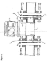
- the electrically operated gas valve consists of the valve body (1), the valve flap (2) with a movable head, located in the said valve body (1) and placed on a sliding axis (8), a flap spring (3) and a flap stabilization spring (4), a cam (5) that serves to open and close the flap (2) by pushing the said axis (8), a cam shaft (6) rotating the cam (5), a worm gear (15) and its counter gear (16), the electric motor (13) which drives the gears (14), a microswitch cam (17) that reports the position of the flap (2), and the control unit (22) wherein the local assessment and control unit (24) providing the opening/closing of the valve and the valve control and measurement unit (30) are contained, as well as the pressure sensor (35) measuring the gas pressure in the valve, the heat sensor (34), the acceleration sensor (36) measuring the vibration and the flanges (9) with movable heads that provide easy connection to the flange pipes (Fig.1).
- Flanges (9) with movable heads that are rotatable around the axis of the valve body (1) and that have a certain number of perforations for the mounting of the pipes, are placed on both ends of the valve body (1).
- these flanges (9) are fitted, by turning, into the stationary flanges on the pipes laid in advance, so that the screw holes match with each other, and are fixed by using bolts and nuts. Sealing is provided by gaskets (9a).
- the position of the valve may be adjusted in conformity with its environment, without any need to cut and reweld the stationary flanges of the pipes (Fig.4).
- the valve body (1) comprises the filter sieve (7), axis (8), valve flap (2), flap sealing gasket (43), flap stabilization spring (4), flap spring (3), cam (5), cam shaft (6), cam shaft passage gasket (44) and the pressure sensor (35) and the heat sensor (34) placed optionally in the valve body (1).
- the filter sieve (7) is placed on the gas inlet port (10) and the gas outlet port (11) of the valve body (1).
- the valve flap (2) is placed inside the valve body (1), vertically to its axis, between the gas inlet and outlet ports (10,11) of the valve.
- the flap (2) is dome-shaped and has a central cavity wide enough for receiving an end portion of the axis (8).
- the flap (2) is fixed onto the axis (8) by mounting an end portion of the axis (8) which is placed in parallel to the axis of the valve body and which moves on this axis.
- the fluttering of the flap (2) is prevented by placing a flap stabilization spring (4) which retains the valve flap (2) in the closed position, between the filter sieve (7) disposed at the valve gas inlet port (10) and the lower surface of the valve flap (2).
- a flap stabilization spring (4) which retains the valve flap (2) in the closed position, between the filter sieve (7) disposed at the valve gas inlet port (10) and the lower surface of the valve flap (2).
- the flap spring (3) is placed between the upper side of the flap (2) and the rabbet formed at the other end of the axis (8), in parallel to the sliding axis (8) in order to enable the valve flap (2) to be in equilibrium, in the closed position.
- the opening and closing of the valve is provided by rotating the cam (5), which opens or closes the valve by working against the flap stabilizing spring (4).
- a cam (5) which is rotated by the cam shaft (6) and the rotational axis of which is on the axis (8) is placed.
- This cam (5) has such a structure that, the outer surfaces of its long and short leg are sloped outwards whereas the inner surfaces are straight and the short leg intersects with the long leg perpendicularly and the sides being straight in a L-shaped structure.
- the rotational axis of the cam (5) is located at the top point of the long leg, and on the axis (8).
- This cam (5) to which the rotational movement obtained by the electrical motor (13) is transmitted by means of the cam shaft (6) which is rotated by the gears (14), moves the axis (8) and thus provides the opening/closing of the valve flap (2).
- the flap stabilizing spring (4) and the flap spring (3) keeps the flap stationary in a closed position, the gas pressure applies force on the flap (2) in the closing direction and thereby helps to provide a full closing ( Figure 2).
- the motor control unit (47) provides the to-and fro-rotation of the motor (13) by means of the valve control and measurement unit microprocessor (31) and the braking of the motor (13) in order to stop the cam (5) exactly at the desired position at the end of the motor driving operation.
- the required information about the position of the cam (5) used for the closing / opening operation is provided by the microswitch cam (17) and the microswitch (18).
- Motor control unit (47) is located in the drive unit (12).
- the drive unit (12) containing more than one gear (14), worm gear (15), batteries (20), electrical motor (13), microswitch cam (17) and microswitch (18) is placed over the valve body (1).
- the electrical motor (13) running with a low voltage and current, drives the worm gear (15) by means of the gears (14), which in turn turns the counter gear (16) (wormgear gear system).
- the gears (14) activate the cam (5) which is connected to the cam shaft (6), by rotating the cam shaft (6).
- the flap (2) comes to the maximum open position.
- This position of the cam (5) is transmitted to the motor control unit (47) by means of the microswitch cam (17) and the microswitch (18) which are located on the counter gear (16) in an almost contact position with each other.
- the motor control unit (47) applies electronic braking to the electrical motor in order to stop the cam (5) at the top point.
- a much less rotation of the motor (13) and dropping the cam (5) down from the top point would be sufficient.
- the flap stabilization spring (4) closes the valve rapidly. An extra power is not consumed by the valve in order to maintain its position (Fig.5).
- the control unit (22), comprising the indicator unit (29), cable communication interface (38), (wireless) radio communication interface (39), valve control and measurement unit (30), and local assessment and control unit (24), is connected to the valve by a connection adaptor (21).
- connection adaptor (21) can be fastened to the valve by turning at 90° angles and the control unit (22) can be installed on the valve (vertical, perpendicular and at both directions) a position that is most suitable to the valve, by means of the said connection adaptor (21).
- the communication of the valve with the external control units is provided by the cable communication interface (38) and the (wireless) radio communication interface (39).
- the cable communication interface (38) is provided by a USART that provides connection to normal PCs or to POS stations at RS 232 or RS 485 standards; whereas the (wireless) radio communication interface (39) is an interface that provides the meter readings as AMR (Auto maticol Meter Reading) and the remote bidirectional control of the valves through the wireless.
- the valve control and measurement unit (30) comprises a motor control unit (47), a valve control and measurement unit microprocessor (31), a valve control and measurement unit Eeprom (32), a gas pulse detector (33), heat sensor (34), pressure sensor (35), acceleration sensor (36), battery cover and meter junction control connections an amplificator (37) (Fig.7).
- the analog signals from the heat sensor (34), pressure sensor (35) and acceleration sensor (36) are amplified by the amplificator (37) and are converted to digital signals by the ADC (analog to digital converter) and transferred to the valve control and measurement unit micro processor (31), wherein such data as close/open commands related to the valve, and such measurement readings as the gas pulse, heat, pressure, acceleration, and battery energy level are received the required calculations are made and these informations are sent to the local assessment and control unit microprocessor (25) by means of the serial channel control bus (23).
- This serial channel control bus (23) contains and carries the I 2 C bus signals serving for the communication between the valve control and measurement unit (30) and the local assessment and control unit (24), as well as the signals required for the distribution of the power provided by the power unit (19) and the control signals of all units.
- the valve can be used as a volume corrector valve and as industrial control valves connected to computer systems in the industrial area, when pressure and heat sensors (35, 34) are attached to it.
- the valve can also be used as a volume corrector.
- the connections may be with or without cable or as a multi-drop bus connection.
- the valve may be used for the purpose of cutting off the gas in case of fire or earthquake, the valve is able to cut off the gas flow upon a warning from the acceleration sensor (36) situated on itself.
- the valve can be closed by a warning from the central control, by mounting a wireless communication interface (39) on it.
- Sensitive seismic sensors located at different points sense the seismic waves and transfer to the center via radio.
- An evaluation is made at the center by determining when an earthquake warning comes after a particular number of the said sensors and if it is decided as the result of this evaluation, that an earthquake is occurring, transmits this information from its own transmitting antenna.
- the valve receives this transmission through the radio placed on it self, it cuts off the gas flow. The time interval to pass between the transmission of the warning by the sensors and the gas flow cut off, is below one second.
- the battery cover and meter junction control connections (45) consist of the reed switch used in order that the interventions to be made to the valve could be sensed by the valve control and measurement unit microprocessor (31) and of the battery (20) and device cover contacts determining the position of the battery cover.
- the pulses coming in a frequency that is proportional to the amount of the gas passing through the meter are detected by a gas pulse detector (33).
- the gas pulse inlet filter circuit (41) consisting of a coil and capacitor circuit elements, provided in the said gas pulse detector (33) protects the gas pulse from interferences.
- the gas pulse passing through the filter reaches the valve control and measurement unit microprocessor (31) after its logic level is checked by an inverter.
- the pulse cable connection control inlet filter circuit (42) consisting of a coil and capacitor circuit elements, protects the connection control between the meter pulser and the valve electronics.
- the connection control data passing through the pulse cable connection control inlet filter circuit (42) reaches the valve control and measurement unit microprocessor (31) after its logic level is checked by an inverter.
- the valve control and measurement unit EE prom (32) is used to retain such data as the position, heat, pressure and acceleration values of the valve in the memory, in case there is an energy interruption due to any reason.
- the electric motor (13) is turned in two directions by a bridge circuit formed by the CR1, CR2, CR4, CR5 diodes and Q1, Q2, Q3 ve Q4 transistors.
- the power supply to the electric motor (13) is cut by making the outputs A and B from the valve control and measurement unit microprocessor (31), logic "0" signal, and the K2 relay coil is energized by applying the logic "1" signal to the end C; in order to stop the electrical motor (13). This trips the K1 relay contact and applies braking by short-circuiting the electrical motor (13).
- the local assessment and control unit (24) consists of the local assessment and control unit microprocessor (25), local assessment and control unit EE prom (26), the indicator unit (29), a sound warning unit (28) and infra red communication unit (27); ( Figure 8).
- the local assessment and control unit microprocessor (25) is a central microprocessor which receives the information calculated and assessed by the valve control and measurement unit microprocessor (31) by means of the serial channel control bus (23) and which provides the required operations in line with the received data and displays the said data on the LCD display screen at the indicator unit (29).
- the sound warning unit (28) which is used to give sound warning signals and consists of a buzzer, a transistor and resistances.
- the infrared communication unit (27) which is used to provide infrared communication with the external devices and consists of a transmitter and a receiver.
- the power unit (19), used by the data processing and crediting channel interface (40), the radio communication interface (39), valve control and measurement unit (30), local assessment and control unit (24) interfaces, is fed by the internal battery (20).
- the system energy is provided by a low level DC source that can be connected to the external low level DC source input ends.
- the diode and a resistance located at the inlet of the low level DC source enable these two sources to feed the system without flowing into one another.
- Two resistors and one condensator located at the internal battery (20) entry enables the level detector to generate warning when the battery (20) is dismounted.
- the potential value at the end of the condensator is lowered to a level suitable for use in the logic circuits and this value is kept constant.
- Three condensators connected to the potential regulator serve as filters. Diode, resistance and capacitor circuit members are used that another level detector in the power unit (1) creates a logic "0" value at the reset level. Two resistors connected to the said level detector provide the application of the reset signal to the bus.
- the electrical load contained in the battery (20) is defined by measuring the battery potential and impedance. This is done by passing current with two different values through the battery and by measuring the voltage of the battery at these current values by means of the valve control and measurement unit microprocessor (31) ADC; and finally its impedance is calculated, in order to decide whether the battery could be used or not.
- the battery test unit (48) is connected to the valve control and measurement unit microprocessor (31) by four wires. These are, the first and second current control ends connecting the potentials at which different currents wile pass to the battery, and the first and second battery level ends connecting the battery voltage to the value control and measurement unit microprocessor (31) ADC.
- the power unit is provided with Ul potential detector, in order to see whether the internal battery is connected or not. If the internal battery is connected, a logic "0" signal is sent to the serial channel control bus, not a logic "1" signal.
- the R17 resistance provides a zero value for the potential detector inlet, when there is no battery; whereas R18 is the pull-up resistance of the potential detector collector outlet.
- a CR6 zener diode provides the insulation so that the C 11 capacitor value is not effected.
- U2 potential regulator serves to prevent the circuit from being effected from a potential loss that may occur in the internal battery. Power shifting is prevented by using the CR7 and CR8 circuit members. By using the reset circuit, the internal battery is enabled to give a start up signal when connected to the circuit. Additionally, the two different battery potential values obtained from ADC are measured in the battery test unit (48) in order to assess the impedance of the battery to decide whether to replace it or not (Fig.9).
- the valve may be used with the devices that have to be operated by battery (20) for a long time. Its open/close position is changed by consuming very little energy and does not need extra energy to maintain its position.
- a non-inventive valve can also perform proportional opening/closing.
- the shape of the cam (5) placed on the axis (8) is changed and made elliptical (Fig. 3).
- the position information of the cam (5) used for proportional opening/closing is obtained by the rotation of the feed-back potentiometer used instead of the microswitch (18), by a gear (14) used for the microswitch cam (17) and pro cessing the potential value being read by the potentiometer by ADC and assessing it by the value control and measurement unit microprocessor (31).
- the flap position control connection (46) consists of an inverter, a valve position control microswitch (18) showing whether the valve is completely open or closed, which is connected to the valve control and measurement module microprocessor and of an amplificator (37) to the ADC end of which the valve control and measurement unit microprocessor (31) of the potentiometer is connected.
- a negative or positive mean bridge current is provided by giving the signals at the ends A and B, at disymmetrical periods in the course of the time.
Landscapes
- Engineering & Computer Science (AREA)
- General Engineering & Computer Science (AREA)
- Mechanical Engineering (AREA)
- Physics & Mathematics (AREA)
- Fluid Mechanics (AREA)
- Electromagnetism (AREA)
- Indication Of The Valve Opening Or Closing Status (AREA)
- Mechanically-Actuated Valves (AREA)
- Temperature-Responsive Valves (AREA)
- Magnetically Actuated Valves (AREA)
- Electrically Driven Valve-Operating Means (AREA)
- Valve Device For Special Equipments (AREA)
- Saccharide Compounds (AREA)
Claims (15)
- Intelligentes Ventil, das einen Ventilkörper (1) und Flansche (9) mit beweglichen Köpfen, die um eine Achse des Ventilkörpers (1) drehbar sind und eine bestimmte Anzahl von Perforationen für die Anbringung von Rohren mit stationären Flanschen mit Schraub-Löchern besitzen, die an beiden Enden des Ventilkörpers (1) angeordnet sind, umfasst, wobei während der Installation des Ventils die Flansche (9) durch Drehen in die stationären Flansche an den im Voraus verlegten Rohren eingesetzt werden, so dass die Schraub-Löcher mit den Perforationen der Flansche (9) übereinstimmen und unter Verwendung von Schrauben und Muttern befestigt werden können, und dass die Position des Ventils in Übereinstimmung mit seiner Umgebung einstellbar ist, ohne dass die stationären Flansche der Rohre abgeschnitten und erneut verschweißt werden müssen, wobei in dem Ventilkörper (1) senkrecht zu dessen Achse eine Ventilklappe (2) zwischen einem Gaseinlassanschluss (10) und einem Gasauslassanschluss (11) des Ventils angeordnet ist, wobei die Ventilklappe (2) haubenförmig ist und einen mittleren Hohlraum besitzt, der weit genug ist, um einen Endabschnitt einer Welle (8) aufzunehmen, wobei die Ventilklappe (2) an der Welle (8) durch Anbringen eines Endabschnitts der Welle (8), der parallel zu der Achse des Ventilkörpers (1) angeordnet ist und sich längs dieser Achse des Ventilkörpers (1) bewegt, befestigt ist, wobei eine Klappenfeder (3) an einer unteren Oberfläche der Ventilklappe (2) angeordnet ist, um die Ventilklappe (2) in der geschlossenen Stellung im Gleichgewicht zu halten, wobei ein Schwenken der Ventilklappe (2) durch Anordnen einer Klappenstabilisierungsfeder (4) auf einer oberen Oberfläche der Ventilklappe (2) verhindert wird, wobei auf der Welle (8) ein Nocken (5) angeordnet ist, der durch eine Nockenwelle (6) gedreht wird, wobei der Nocken (5) eine L-förmige Struktur hat, die einen langen Schenkel und einen kurzen Schenkel, der den langen Schenkel bei Betrachtung in Richtung der Drehachse der Nockenwelle (6) senkrecht schneidet, umfasst, wobei in derselben Ansicht Außenkantenflächen (5a) der L-förmigen Struktur nach außen geneigt sind, während Innenkantenflächen (5b) der L-förmigen Struktur geradlinig sind und die Drehachse der Nockenwelle (6) eine Drehachse der Welle (8) senkrecht schneidet, wobei der Nocken (5), an den die durch einen Elektromotor (13) erhaltene Drehbewegung mittels der Nockenwelle (6) übertragen wird, die durch ein Getriebe (14) gedreht wird, die Welle (8) parallel zu der Achse des Ventilkörpers (1) bewegt und somit das Öffnen/Schließen der Ventilklappe (2), mit der die Welle (8) verbunden ist, hervorruft.
- Intelligentes Ventil nach Anspruch 1,
dadurch gekennzeichnet, dass
die Klappenfeder (3), die die Ventilklappe (2) in der geschlossenen Stellung im Gleichgewicht hält, zwischen einem Filtersieb (7), das am Gaseinlassanschluss (10) angeordnet ist, und der unteren Oberfläche der Ventilklappe (2) angeordnet ist. - Intelligentes Ventil nach Anspruch 1 oder 2,
dadurch gekennzeichnet, dass
die Klappenstabilisierungfeder (4) konzentrisch zu der Welle (8) zwischen der oberen Oberfläche der Ventilklappe (2) und einer am anderen Ende der Welle (8) ausgebildeten Fuge angeordnet ist, um ein Schwenken der Ventilklappe (2) zu verhindern. - Intelligentes Ventil nach einem der Ansprüche 1 bis 3,
gekennzeichnet durch
eine Antriebseinheit (12), die aus dem Elektromotor (13), der mit einer niedrigen Spannung und einem niedrigen Strom läuft; dem Getriebe (14); einem Schneckenradvorgelege (15); einem Vorgelegerad (16); einem Mikroschalternocken (17) und einem Mikroschalter (18), die sich an dem Vorgelegerad (16) in einer Position befinden, in der sie fast in Kontakt sind, besteht; wobei der Mikroschalternocken (17) Daten bezüglich der Position des Nockens (5), der zum Öffnen/Schließen der Ventilklappe (2) verwendet wird, an eine Motorsteuereinheit (47) überträgt und außerdem den Mikroschalter (18) öffnen und schließen kann; wobei die Antriebseinheit (12) jene ist, die eine Vorwärts- und Rückwärtsdrehung des Elektromotors (13) mittels einer Ventilsteuerung und eines Messeinheit-Mikroprozessors (31) schafft und den Elektromotor (13) bremst, um den Nocken (5) exakt an einer gewünschten Position am Ende des Motorantriebsbetriebs anzuhalten. - Intelligentes Ventil nach einem der Ansprüche 1 bis 4,
gekennzeichnet durch
einen Drucksensor (35), der den Druck des in das Ventil eintretenden Gases misst, und einen Wärmesensor (34), der dessen Wärme misst, die in einem Abschnitt des Ventilkörpers (1) zwischen dem Filtersieb (9), das in den Gaseinlassanschluss (10) eingesetzt ist, und der Ventilklappe (10) angeordnet sind, so dass das Ventil als eine Gasvolumen-Korrektureinrichtung verwendet werden kann. - Intelligentes Ventil nach einem der Ansprüche 1 bis 5,
gekennzeichnet durch
eine Kabelkommunikation-Schnittstelle, die durch einen USART bereitgestellt wird, der eine Verbindung mit normalen PCs oder mit POS-Stationen mit RS 232- oder RS 485-Standards schafft. - Intelligentes Ventil nach einem der Ansprüche 1 bis 6,
gekennzeichnet durch
eine (drahtlose) Funkkommunikationsschnittstelle (39), die eine Schnittstelle ist, die Messgerätablesungen als AMR (automatische Messgerätablesung, Automatical Meter Reading) und die bidirektionale Fernsteuerung des Ventils schafft. - Intelligentes Ventil nach einem der Ansprüche 4 bis 7,
gekennzeichnet durch
den Ventilsteuerungs- und Messeinheit-Mikroprozessor (31), der die Befehle für den Ventilöffnungs-/Ventilschließbetrieb liefert, der Berechnungen unter Verwendung von Messdaten als Gasimpulsdaten, die von einem Gasimpulsdetektor erhalten werden, als Wärmedaten, die von dem Wärmesensor (34) erhalten werden, als Druckdaten, die von dem Drucksensor (35) erhalten werden, und als Beschleunigungsdaten, die von einem Beschleunigungssensor (36) erhalten werden, für Batterieenergiepegel-Daten einer internen Batterie (20) ausführt und diese Daten an einen lokalen Bemessungs- und Steuereinheit-Mikroprozessor (25) mittels eines Steuerbusses (23) mit seriellem Kanal überträgt. - Intelligentes Ventil nach einem der Ansprüche 1 bis 7,
gekennzeichnet durch
einen Ventilsteuerungs- und Messeinheit-EEPROM (32), der verwendet wird, um Daten wie etwa die Positions-, Wärme-, Druck- und Beschleunigungswert-Daten des Ventils in einem Speicher zu halten, falls aus irgendeinem Grund eine Unterbrechung der Energiezufuhr auftritt. - Intelligentes Ventil nach Anspruch 8 oder Anspruch 9,
gekennzeichnet durch
den lokalen Bemessungs- und Steuereinheit-Mikroprozessor (25), der in einer lokalen Bemessungs- und Steuereinheit (24) zusammen mit einem lokalen Bemessungs- und Steuereinheit-EEPROM (26), einer Anzeigeeinheit (29), einer akustischen Warneinheit (28) und einer Infrarotkommunikationseinheit (27) enthalten ist; der die durch den Ventilsteuerungs- und Messeinheit-Mikroprozessor (31) berechneten und bemessenen Informationen mittels des Steuerbusses (23) mit seriellem Kanal empfängt und der die erforderlichen Operationen zusammen mit den empfangenen Daten bereitstellt und diese Daten auf einem LCD-Anzeigeschirm in der Anzeigeeinheit (29) anzeigt. - Intelligentes Ventil nach Anspruch 10,
dadurch gekennzeichnet, dass
der lokalen Bemessungs- und Steuereinheit-EEPROM (26) alle Informationen in seinem Speicher hält, wenn die Energiezufuhr aus irgendeinem Grund unterbrochen wird. - Intelligentes Ventil nach einem der Ansprüche 4 bis 11,
dadurch gekennzeichnet, dass
der Ventilsteuerungs- und Messeinheit-Prozessor (31) die Positionsinformationen des Nockens (5), die durch die Drehung eines Rückkopplungspotentiometers durch das Getriebe (14) erhalten werden, verarbeitet und bewertet, wobei der verarbeitete Potentialwert durch das Potentiometer mittels ADC gelesen wird. - Intelligentes Ventil nach einem der Ansprüche 10 bis 12,
dadurch gekennzeichnet, dass
die Infrarotkommunikationseinheit (27), die dazu verwendet wird, eine Infrarotkommunikation mit externen Vorrichtungen zu schaffen, aus einem Sender und einem Empfänger besteht. - Intelligentes Ventil nach einem der Ansprüche 8 bis 13,
dadurch gekennzeichnet, dass
die interne Batterie (20) Leistung bereitstellt, die von einer Datenverarbeitungs- und Kreditierungskanal-Schnittstelle (40), der Funkkommunikationsschnittstelle (39), einer Ventilsteuerungs- und Messeinheit-Schnittstelle und einer lokalen Bemessungs- und Steuereinheit-Schnittstelle genutzt wird. - Intelligentes Ventil nach Anspruch 14,
gekennzeichnet durch
eine Leistungseinheit (19), die aus einer Gleichspannungsquelle mit niedrigem Pegel besteht, die an die Eingangsenden einer externen Gleichspannungsquelle mit niedrigem Pegel anschließbar ist und die Leistung bereitstellt, die von der Datenverarbeitungs- und Kreditierungskanal-Schnittstelle (40), der Funkkommunikationsschnittstelle (39), der Ventilsteuerungs- und Messeinheit-Schnittstelle und der lokalen Bemessungs- und Steuereinheit-Schnittstelle genutzt wird.
Applications Claiming Priority (3)
| Application Number | Priority Date | Filing Date | Title |
|---|---|---|---|
| TR200000631 | 2000-03-06 | ||
| TR200000631 | 2000-03-06 | ||
| PCT/TR2001/000011 WO2001066984A2 (en) | 2000-03-06 | 2001-03-02 | Valve |
Publications (2)
| Publication Number | Publication Date |
|---|---|
| EP1261823A2 EP1261823A2 (de) | 2002-12-04 |
| EP1261823B1 true EP1261823B1 (de) | 2006-06-14 |
Family
ID=21622389
Family Applications (1)
| Application Number | Title | Priority Date | Filing Date |
|---|---|---|---|
| EP01924080A Expired - Lifetime EP1261823B1 (de) | 2000-03-06 | 2001-03-02 | Ventil |
Country Status (6)
| Country | Link |
|---|---|
| EP (1) | EP1261823B1 (de) |
| AT (1) | ATE330155T1 (de) |
| AU (1) | AU5074001A (de) |
| DE (1) | DE60120649T2 (de) |
| ES (1) | ES2266191T3 (de) |
| WO (1) | WO2001066984A2 (de) |
Cited By (1)
| Publication number | Priority date | Publication date | Assignee | Title |
|---|---|---|---|---|
| WO2021003993A1 (zh) * | 2019-07-05 | 2021-01-14 | 广东金力变速科技股份有限公司 | 一种阀掣动装置 |
Families Citing this family (9)
| Publication number | Priority date | Publication date | Assignee | Title |
|---|---|---|---|---|
| EP1948966A1 (de) | 2005-11-14 | 2008-07-30 | Borgwarner, Inc. | Betätigungsmechanismus mit integriertem antriebsmechanismus |
| JP2009534007A (ja) | 2006-04-07 | 2009-09-17 | ボーグワーナー・インコーポレーテッド | 一体化された駆動機構付きアクチュエータ |
| EP2267342A1 (de) * | 2009-03-09 | 2010-12-29 | TA-Regulator | Druckunabhängiges Regelventil |
| RU2467232C1 (ru) * | 2011-11-09 | 2012-11-20 | Общество с ограниченной ответственностью фирма "Саратовгазприборавтоматика" | Клапан запорный электроприводной |
| CN105917970A (zh) * | 2016-06-30 | 2016-09-07 | 成都微田园都市农业科技有限公司 | 一种智能家居蘑菇柜 |
| AU2017346943A1 (en) | 2016-10-21 | 2018-07-05 | Silicon Controls Pty Ltd | An electronic device |
| CN108036097B (zh) * | 2018-01-16 | 2023-08-04 | 江苏华东正大空调设备有限公司 | 一种远控全自动阀门的控制方法 |
| IT201900003723A1 (it) * | 2019-03-14 | 2020-09-14 | Kerberos S R L | Dispositivo per domotica |
| CN116146725B (zh) * | 2022-11-16 | 2025-11-14 | 江苏上龙供水设备有限公司 | 一种高性能双通道蝶阀 |
Family Cites Families (5)
| Publication number | Priority date | Publication date | Assignee | Title |
|---|---|---|---|---|
| US1758419A (en) * | 1929-05-15 | 1930-05-13 | Aw Wheaton Brass Works | Valve |
| FR972209A (fr) * | 1948-09-23 | 1951-01-26 | Robinet | |
| FR1569121A (de) * | 1968-04-19 | 1969-05-30 | ||
| US4343336A (en) * | 1978-01-24 | 1982-08-10 | Trygg Lars Erik | Liquid dispensing device |
| IT1199046B (it) * | 1982-07-29 | 1988-12-21 | Edi System Srl | Valvola direzionale a spillo a due vie,ad azionamento elettromagnetico,normalmente chiusa |
-
2001
- 2001-03-02 WO PCT/TR2001/000011 patent/WO2001066984A2/en not_active Ceased
- 2001-03-02 AU AU50740/01A patent/AU5074001A/en not_active Abandoned
- 2001-03-02 EP EP01924080A patent/EP1261823B1/de not_active Expired - Lifetime
- 2001-03-02 AT AT01924080T patent/ATE330155T1/de not_active IP Right Cessation
- 2001-03-02 DE DE60120649T patent/DE60120649T2/de not_active Expired - Lifetime
- 2001-03-02 ES ES01924080T patent/ES2266191T3/es not_active Expired - Lifetime
Cited By (1)
| Publication number | Priority date | Publication date | Assignee | Title |
|---|---|---|---|---|
| WO2021003993A1 (zh) * | 2019-07-05 | 2021-01-14 | 广东金力变速科技股份有限公司 | 一种阀掣动装置 |
Also Published As
| Publication number | Publication date |
|---|---|
| ATE330155T1 (de) | 2006-07-15 |
| DE60120649D1 (de) | 2006-07-27 |
| AU5074001A (en) | 2001-09-17 |
| WO2001066984A2 (en) | 2001-09-13 |
| WO2001066984A3 (en) | 2001-12-13 |
| ES2266191T3 (es) | 2007-03-01 |
| EP1261823A2 (de) | 2002-12-04 |
| DE60120649T2 (de) | 2007-05-31 |
Similar Documents
| Publication | Publication Date | Title |
|---|---|---|
| US5139044A (en) | Fluid control system | |
| EP1261823B1 (de) | Ventil | |
| US5228469A (en) | Fluid control system | |
| US6229448B1 (en) | Intrinsically safe fluid tank overfill protection system | |
| US20060124171A1 (en) | Secure wireless leak detection system | |
| JP2003519857A (ja) | 施設からデータを取り込むシステムおよび方法 | |
| CN206504834U (zh) | 一种液体泄漏定位检测装置 | |
| US7221282B1 (en) | Wireless wastewater system monitoring apparatus and method of use | |
| EP1913296A2 (de) | Vorrichtung zur ventilverbindung und -steuerung | |
| AU2018229439B2 (en) | Liquid gas level measuring system | |
| CA2079028A1 (en) | Automatic shutoff valve | |
| US6328053B1 (en) | Automatic actuator system | |
| CN210035087U (zh) | 一种管道测压装置 | |
| CN212273235U (zh) | 一种智能流体泄漏保护装置 | |
| EP4042044B1 (de) | Verfahren zum bestimmen einer position eines sperrelementes in einem ventil, ein sensorsystem und verwendung eines sensorsystems | |
| WO2012176008A1 (en) | Liquid flow rate meter with safety shut-off valve | |
| US20250224261A1 (en) | Compact water meter | |
| KR101126146B1 (ko) | 수처리설비 원방 감시제어 시스템의 감압밸브 구동장치 | |
| JP7792638B2 (ja) | 水道メータユニット制御システム | |
| CN213364804U (zh) | 给水泵转速与反转测量装置 | |
| CN111689083A (zh) | 液体储罐液位、压力、温度三位一体集成监测装置 | |
| CN111486268A (zh) | 一种智能流体泄漏保护装置及其控制方法 | |
| JP2000213742A (ja) | ガス保安装置 | |
| KR20200009513A (ko) | 가스 누설 차단기 | |
| CN120027271A (zh) | 阀位变送器 |
Legal Events
| Date | Code | Title | Description |
|---|---|---|---|
| PUAI | Public reference made under article 153(3) epc to a published international application that has entered the european phase |
Free format text: ORIGINAL CODE: 0009012 |
|
| 17P | Request for examination filed |
Effective date: 20020919 |
|
| AK | Designated contracting states |
Kind code of ref document: A2 Designated state(s): AT BE CH CY DE DK ES FI FR GB GR IE IT LI LU MC NL PT SE TR |
|
| AX | Request for extension of the european patent |
Free format text: AL PAYMENT 20020919;LT PAYMENT 20020919;LV PAYMENT 20020919;MK PAYMENT 20020919;RO PAYMENT 20020919;SI PAYMENT 20020919 |
|
| 17Q | First examination report despatched |
Effective date: 20050406 |
|
| GRAP | Despatch of communication of intention to grant a patent |
Free format text: ORIGINAL CODE: EPIDOSNIGR1 |
|
| GRAS | Grant fee paid |
Free format text: ORIGINAL CODE: EPIDOSNIGR3 |
|
| GRAA | (expected) grant |
Free format text: ORIGINAL CODE: 0009210 |
|
| AK | Designated contracting states |
Kind code of ref document: B1 Designated state(s): AT BE CH CY DE DK ES FI FR GB GR IE IT LI LU MC NL PT SE TR |
|
| AX | Request for extension of the european patent |
Extension state: AL LT LV MK RO SI |
|
| PG25 | Lapsed in a contracting state [announced via postgrant information from national office to epo] |
Ref country code: IT Free format text: LAPSE BECAUSE OF FAILURE TO SUBMIT A TRANSLATION OF THE DESCRIPTION OR TO PAY THE FEE WITHIN THE PRESCRIBED TIME-LIMIT;WARNING: LAPSES OF ITALIAN PATENTS WITH EFFECTIVE DATE BEFORE 2007 MAY HAVE OCCURRED AT ANY TIME BEFORE 2007. THE CORRECT EFFECTIVE DATE MAY BE DIFFERENT FROM THE ONE RECORDED. Effective date: 20060614 Ref country code: NL Free format text: LAPSE BECAUSE OF FAILURE TO SUBMIT A TRANSLATION OF THE DESCRIPTION OR TO PAY THE FEE WITHIN THE PRESCRIBED TIME-LIMIT Effective date: 20060614 Ref country code: FI Free format text: LAPSE BECAUSE OF FAILURE TO SUBMIT A TRANSLATION OF THE DESCRIPTION OR TO PAY THE FEE WITHIN THE PRESCRIBED TIME-LIMIT Effective date: 20060614 Ref country code: AT Free format text: LAPSE BECAUSE OF FAILURE TO SUBMIT A TRANSLATION OF THE DESCRIPTION OR TO PAY THE FEE WITHIN THE PRESCRIBED TIME-LIMIT Effective date: 20060614 Ref country code: CH Free format text: LAPSE BECAUSE OF FAILURE TO SUBMIT A TRANSLATION OF THE DESCRIPTION OR TO PAY THE FEE WITHIN THE PRESCRIBED TIME-LIMIT Effective date: 20060614 Ref country code: LI Free format text: LAPSE BECAUSE OF FAILURE TO SUBMIT A TRANSLATION OF THE DESCRIPTION OR TO PAY THE FEE WITHIN THE PRESCRIBED TIME-LIMIT Effective date: 20060614 Ref country code: BE Free format text: LAPSE BECAUSE OF FAILURE TO SUBMIT A TRANSLATION OF THE DESCRIPTION OR TO PAY THE FEE WITHIN THE PRESCRIBED TIME-LIMIT Effective date: 20060614 |
|
| REG | Reference to a national code |
Ref country code: GB Ref legal event code: FG4D |
|
| REG | Reference to a national code |
Ref country code: CH Ref legal event code: EP |
|
| REG | Reference to a national code |
Ref country code: IE Ref legal event code: FG4D |
|
| REF | Corresponds to: |
Ref document number: 60120649 Country of ref document: DE Date of ref document: 20060727 Kind code of ref document: P |
|
| PG25 | Lapsed in a contracting state [announced via postgrant information from national office to epo] |
Ref country code: DK Free format text: LAPSE BECAUSE OF FAILURE TO SUBMIT A TRANSLATION OF THE DESCRIPTION OR TO PAY THE FEE WITHIN THE PRESCRIBED TIME-LIMIT Effective date: 20060914 Ref country code: SE Free format text: LAPSE BECAUSE OF FAILURE TO SUBMIT A TRANSLATION OF THE DESCRIPTION OR TO PAY THE FEE WITHIN THE PRESCRIBED TIME-LIMIT Effective date: 20060914 |
|
| PG25 | Lapsed in a contracting state [announced via postgrant information from national office to epo] |
Ref country code: PT Free format text: LAPSE BECAUSE OF FAILURE TO SUBMIT A TRANSLATION OF THE DESCRIPTION OR TO PAY THE FEE WITHIN THE PRESCRIBED TIME-LIMIT Effective date: 20061114 |
|
| LTIE | Lt: invalidation of european patent or patent extension |
Effective date: 20060614 |
|
| NLV1 | Nl: lapsed or annulled due to failure to fulfill the requirements of art. 29p and 29m of the patents act | ||
| REG | Reference to a national code |
Ref country code: CH Ref legal event code: PL |
|
| ET | Fr: translation filed | ||
| REG | Reference to a national code |
Ref country code: ES Ref legal event code: FG2A Ref document number: 2266191 Country of ref document: ES Kind code of ref document: T3 |
|
| PLBE | No opposition filed within time limit |
Free format text: ORIGINAL CODE: 0009261 |
|
| STAA | Information on the status of an ep patent application or granted ep patent |
Free format text: STATUS: NO OPPOSITION FILED WITHIN TIME LIMIT |
|
| 26N | No opposition filed |
Effective date: 20070315 |
|
| GBPC | Gb: european patent ceased through non-payment of renewal fee |
Effective date: 20070302 |
|
| PG25 | Lapsed in a contracting state [announced via postgrant information from national office to epo] |
Ref country code: IE Free format text: LAPSE BECAUSE OF NON-PAYMENT OF DUE FEES Effective date: 20070302 Ref country code: MC Free format text: LAPSE BECAUSE OF NON-PAYMENT OF DUE FEES Effective date: 20070331 |
|
| PG25 | Lapsed in a contracting state [announced via postgrant information from national office to epo] |
Ref country code: GB Free format text: LAPSE BECAUSE OF NON-PAYMENT OF DUE FEES Effective date: 20070302 Ref country code: GR Free format text: LAPSE BECAUSE OF FAILURE TO SUBMIT A TRANSLATION OF THE DESCRIPTION OR TO PAY THE FEE WITHIN THE PRESCRIBED TIME-LIMIT Effective date: 20060915 |
|
| PGFP | Annual fee paid to national office [announced via postgrant information from national office to epo] |
Ref country code: ES Payment date: 20090325 Year of fee payment: 9 |
|
| PG25 | Lapsed in a contracting state [announced via postgrant information from national office to epo] |
Ref country code: CY Free format text: LAPSE BECAUSE OF FAILURE TO SUBMIT A TRANSLATION OF THE DESCRIPTION OR TO PAY THE FEE WITHIN THE PRESCRIBED TIME-LIMIT Effective date: 20060614 Ref country code: LU Free format text: LAPSE BECAUSE OF NON-PAYMENT OF DUE FEES Effective date: 20070302 |
|
| PGFP | Annual fee paid to national office [announced via postgrant information from national office to epo] |
Ref country code: FR Payment date: 20090318 Year of fee payment: 9 |
|
| REG | Reference to a national code |
Ref country code: FR Ref legal event code: ST Effective date: 20101130 |
|
| PG25 | Lapsed in a contracting state [announced via postgrant information from national office to epo] |
Ref country code: FR Free format text: LAPSE BECAUSE OF NON-PAYMENT OF DUE FEES Effective date: 20100331 |
|
| REG | Reference to a national code |
Ref country code: ES Ref legal event code: FD2A Effective date: 20110415 |
|
| PG25 | Lapsed in a contracting state [announced via postgrant information from national office to epo] |
Ref country code: ES Free format text: LAPSE BECAUSE OF NON-PAYMENT OF DUE FEES Effective date: 20110404 |
|
| PG25 | Lapsed in a contracting state [announced via postgrant information from national office to epo] |
Ref country code: ES Free format text: LAPSE BECAUSE OF NON-PAYMENT OF DUE FEES Effective date: 20100303 |
|
| PGFP | Annual fee paid to national office [announced via postgrant information from national office to epo] |
Ref country code: TR Payment date: 20120302 Year of fee payment: 12 |
|
| PGFP | Annual fee paid to national office [announced via postgrant information from national office to epo] |
Ref country code: DE Payment date: 20120529 Year of fee payment: 12 |
|
| REG | Reference to a national code |
Ref country code: DE Ref legal event code: R119 Ref document number: 60120649 Country of ref document: DE Effective date: 20131001 |
|
| PG25 | Lapsed in a contracting state [announced via postgrant information from national office to epo] |
Ref country code: DE Free format text: LAPSE BECAUSE OF NON-PAYMENT OF DUE FEES Effective date: 20131001 |
|
| PG25 | Lapsed in a contracting state [announced via postgrant information from national office to epo] |
Ref country code: TR Free format text: LAPSE BECAUSE OF NON-PAYMENT OF DUE FEES Effective date: 20140302 |