EP1262597B1 - Method and system for heating of rail and railelement for use therewith - Google Patents
Method and system for heating of rail and railelement for use therewith Download PDFInfo
- Publication number
- EP1262597B1 EP1262597B1 EP02077191A EP02077191A EP1262597B1 EP 1262597 B1 EP1262597 B1 EP 1262597B1 EP 02077191 A EP02077191 A EP 02077191A EP 02077191 A EP02077191 A EP 02077191A EP 1262597 B1 EP1262597 B1 EP 1262597B1
- Authority
- EP
- European Patent Office
- Prior art keywords
- liquid
- heat
- rail element
- rail
- channel
- Prior art date
- Legal status (The legal status is an assumption and is not a legal conclusion. Google has not performed a legal analysis and makes no representation as to the accuracy of the status listed.)
- Expired - Lifetime
Links
- 238000000034 method Methods 0.000 title claims abstract description 27
- 238000010438 heat treatment Methods 0.000 title claims abstract description 19
- 239000007788 liquid Substances 0.000 claims abstract description 50
- 238000001816 cooling Methods 0.000 claims abstract description 5
- 238000009413 insulation Methods 0.000 claims description 6
- 238000003466 welding Methods 0.000 claims description 3
- 239000003673 groundwater Substances 0.000 claims 1
- XLYOFNOQVPJJNP-UHFFFAOYSA-N water Substances O XLYOFNOQVPJJNP-UHFFFAOYSA-N 0.000 description 4
- 241000269350 Anura Species 0.000 description 2
- 239000003795 chemical substances by application Substances 0.000 description 2
- 230000005494 condensation Effects 0.000 description 2
- 238000009833 condensation Methods 0.000 description 2
- 238000001704 evaporation Methods 0.000 description 2
- 230000008020 evaporation Effects 0.000 description 2
- 238000009434 installation Methods 0.000 description 2
- 239000002184 metal Substances 0.000 description 2
- 229910052751 metal Inorganic materials 0.000 description 2
- RYGMFSIKBFXOCR-UHFFFAOYSA-N Copper Chemical compound [Cu] RYGMFSIKBFXOCR-UHFFFAOYSA-N 0.000 description 1
- 229910045601 alloy Inorganic materials 0.000 description 1
- 239000000956 alloy Substances 0.000 description 1
- 239000004020 conductor Substances 0.000 description 1
- 239000002826 coolant Substances 0.000 description 1
- 229910052802 copper Inorganic materials 0.000 description 1
- 239000010949 copper Substances 0.000 description 1
- 230000007257 malfunction Effects 0.000 description 1
- 238000004519 manufacturing process Methods 0.000 description 1
- 239000000463 material Substances 0.000 description 1
- 150000002739 metals Chemical class 0.000 description 1
- 238000012986 modification Methods 0.000 description 1
- 230000004048 modification Effects 0.000 description 1
- 239000010935 stainless steel Substances 0.000 description 1
- 229910001220 stainless steel Inorganic materials 0.000 description 1
Images


Classifications
-
- E—FIXED CONSTRUCTIONS
- E01—CONSTRUCTION OF ROADS, RAILWAYS, OR BRIDGES
- E01B—PERMANENT WAY; PERMANENT-WAY TOOLS; MACHINES FOR MAKING RAILWAYS OF ALL KINDS
- E01B7/00—Switches; Crossings
- E01B7/24—Heating of switches
-
- F—MECHANICAL ENGINEERING; LIGHTING; HEATING; WEAPONS; BLASTING
- F24—HEATING; RANGES; VENTILATING
- F24T—GEOTHERMAL COLLECTORS; GEOTHERMAL SYSTEMS
- F24T10/00—Geothermal collectors
- F24T10/10—Geothermal collectors with circulation of working fluids through underground channels, the working fluids not coming into direct contact with the ground
-
- Y—GENERAL TAGGING OF NEW TECHNOLOGICAL DEVELOPMENTS; GENERAL TAGGING OF CROSS-SECTIONAL TECHNOLOGIES SPANNING OVER SEVERAL SECTIONS OF THE IPC; TECHNICAL SUBJECTS COVERED BY FORMER USPC CROSS-REFERENCE ART COLLECTIONS [XRACs] AND DIGESTS
- Y02—TECHNOLOGIES OR APPLICATIONS FOR MITIGATION OR ADAPTATION AGAINST CLIMATE CHANGE
- Y02E—REDUCTION OF GREENHOUSE GAS [GHG] EMISSIONS, RELATED TO ENERGY GENERATION, TRANSMISSION OR DISTRIBUTION
- Y02E10/00—Energy generation through renewable energy sources
- Y02E10/10—Geothermal energy
Definitions
- a burner pipe is mounted on a side wall of a rail, wherein the burner pipe is provided with gas radiators or so-called burner holders by which the rail is heated.
- liquid is heated for instance by means of a gas burner installation, and transported to one or more switch points against which a round pipe is clamped which must provide the heat transfer from the liquid in the pipe to the rail.
- an electrical heating element is mounted against a side wall of the web of the rail, which heating element transfers the electrically generated heat to the rail.
- Patent abstracts of Japan Vol. 004, no. 013 & JP 54/149104 teach a method and device for heating a rail element, wherein heat guiding means arrange for the transfer of heat between liquid in a ground supporting the rail element and said rail element.
- the present invention provides a method for heating and/or cooling a rail element, according to claim 10, wherein heating liquid is carried along a channel guiding the liquid during transfer of the heat to or from the rail element, which channel is provided at least partly against at least an upright part of the rail element so as to cause that heat transfer takes place between the liquid and cause that heat transfer takes place between the liquid and the rail element, characterized in that the relatively high temperature or low temperature of the liquid is obtained by extracting heat respectively cold from the ground by arranging pipes for the liquid in the ground.
- the heat to be extracted from the ground can also be carried to the rails via a heat exchanger.
- the temperature of the liquid can moreover be raised (or lowered) if necessary by means of a heat pump.
- the present invention further provides a method for transferring heat from a liquid to a rail element, wherein the heat-exchanging surface between the liquid and the rail element is optimized by guiding the liquid through a channel having one or more walls in heat-conducting contact with the rail element.
- a channel can likewise be of round, oval or other form, such as one or more flexible hoses adjacent to each other.
- the present invention further provides a system for transferring terrestrial heat to a rail element, in accordance with claim 1.
- the rails or other rail elements can also be cooled during the summer with cold liquid from the ground, whereby disruption and noise can be reduced, for instance by condensation on the rail.
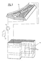
- a switch point 10 as shown schematically in fig. 1 provisions have to be made for heating thereof, so that operation of the switch point remains possible in winter conditions.
- a first rail 12 according to the preferred embodiment of the present invention, space 14 is created using a plate 13 where an upright part 15 extends between a base 16 and a head of the rail 17.
- This space 14 can be used for through-flow of a liquid which is heated for instance to a temperature of +5°C to about 60°C, which is for instance considerably lower than the presently usual temperature of about 80°C, owing to the large exchange surface of the liquid and the rail.
- an elongate channel 18 is fixed to the upright part in heat-conducting manner, for instance using paste 19 or by means of welding or the like, in order to obtain good heat transfer between the liquid in channel 20 and the rail.
- a channel 21 is created by a tubular part 22 of U-shaped cross-section, whereby the channel has a wall in common with a base 23 of a rail 24.
- an elongate channel 26 with a relatively long wall 27 is fixed in the embodiment of fig. 2D to a base 29 of rail 30 using heat-conducting paste or welds.
- heat-conducting paste can be used which preferably remains elastic during the period of use, which can be many years.
- An advantage compared to a number of types of paste which become hard is that, when applied in rails, hardened paste will start to crack due to vibrations, and cracks are heat-insulating. A mass which remains homogenous will continue to conduct heat well.
- the channels shown in any of the fig. 2A-2D are connected to a conduit system 32, a considerable part of which extends over a determined depth in the ground, for instance via loops 33, in order to guide liquid of for instance 5 or 10°C along the switch point 35, also in winter conditions, using pump 36 and reservoir 37.
- a further developed system 41 according to the present invention comprises, in addition to supply source 42 and return source 43 and diverse valves and three-way valves not designated with reference numerals, a heat exchanger 44 to one side of which are connected the primary circuit with supply source 42 and return source 43 of the monosource and a pump 45, and to the other side of which are connected a secondary circuit with pump 47 and the conduits to the rails of a switch point 48. Also included in this circuit is a heat pump 49 which, depending on the dimensioning and/or conditions such as outside temperature, can bring about an increase in the temperature of the water in the channels along rail elements 48 and other movable rail elements such as switch blades and/or crossing frogs.
- a part 71 which is relatively easy to manufacture is provided with two internal channels 72 and 73 for the liquid.
- the channels 81 and 82 are formed by welding close-fitting elements to a rail so that the liquid is in direct contact with the rail.
- a relatively large channel is provided owing to a plate 92 which is welded to the top and bottom side of the rail. Owing to the form of plate 101 the efficiency thereof per quantity of liquid is increased.
- the channel 111 according to fig. 11 can also be fixed to a rail in simple manner.
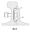
- Channels 102 and 103 of fig. 12 can be manufactured in relatively simple manner.
- pipes or hoses 103, 104 can be readily fixed to rail using a fitting piece 105.
- a special fitting piece 106 is also arranged on the base of the rail to accommodate channels 107, 108.
- the channels 112, 113, 114, 115 are in any case of approximately round shape. Pipes are also arranged on the base of the switch blade of the switch point, which enhances heating thereof, particularly in the case that the switch blade in question does not make contact with the rest of the main pipe of the switch point due to the position of the switch point.
- the pipes are manufactured from a good conducting material at the position of the rails.
- This material is preferably a metal, wherein copper for instance has very good conducting properties and stainless steel for instance has excellent durability. Other metals or alloys can also be applied.
- the embodiment according to fig. 15 comprises a ground loop with heat pump and heat exchanger.
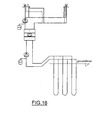
- the embodiment according to fig. 16 is relatively simple in that it comprises a ground loop with heat pump having a relatively small number of components such as connectors and the like.
- the embodiment according to fig. 16 can be applied in a ground loop with heat exchanger and cooling agent, whereby higher temperatures differences can be achieved through evaporation and condensation thereof.
- this cold agent will begin to boil at relatively low temperature through pressure reduction on the primary side of the heat pump, whereby the pump will extract evaporation heat from the ground.
- the temperature of the liquid to the rail element will be increased.
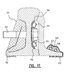
- a further embodiment ( fig. 17 ) is provided with insulation means 131 which are fixed to the rail element by means of spring means 132.
- An alternative method of fixing the insulation means 131 to the rail element is the use of bolt 133.
- This bolt 133 is used in the first instance to fix channels 134 and 135.
- thermal paste 136 For heat conduction of these channels 134 and 135 use is made of thermal paste 136, whereby the heat of the liquid is conducted well to the rail element.
- This embodiment is further provided with liquid channels 137 and 138 which are fixed to the switch blade of the point by means of clamping spring 139.
- a heat-conducting paste 140 is likewise applied here.
- the embodiments are very practicable and can be installed in existing rail and switch point systems.
Landscapes
- Engineering & Computer Science (AREA)
- Mechanical Engineering (AREA)
- Architecture (AREA)
- Civil Engineering (AREA)
- Structural Engineering (AREA)
- Life Sciences & Earth Sciences (AREA)
- Sustainable Development (AREA)
- Sustainable Energy (AREA)
- Chemical & Material Sciences (AREA)
- Combustion & Propulsion (AREA)
- General Engineering & Computer Science (AREA)
- Machines For Laying And Maintaining Railways (AREA)
- Heat Treatment Of Articles (AREA)
- Railway Tracks (AREA)
- Road Paving Structures (AREA)
Abstract
Description
- It is known that heating of switch points has the function of enabling the points to switch without problem during wintery conditions, i.e. the sticking together of components as a result of being frozen is prevented; similar problems can occur as a result of snow and/or drift snow.
- In a known so-called gas burner pipe installation a burner pipe is mounted on a side wall of a rail, wherein the burner pipe is provided with gas radiators or so-called burner holders by which the rail is heated.
- In the central pipe system liquid is heated for instance by means of a gas burner installation, and transported to one or more switch points against which a round pipe is clamped which must provide the heat transfer from the liquid in the pipe to the rail.
- In the electrical heating system an electrical heating element is mounted against a side wall of the web of the rail, which heating element transfers the electrically generated heat to the rail.
- Known from the publication of
European application EP 0 247 693 A2 is a heating method for heating railway points by applying a warm liquid which is carried along the rail element, wherein heat transfer takes place between the liquid and the rail element. - Patent abstracts of Japan Vol. 004, no. 013 &
JP 54/149104 - In order to improve such a method the present invention provides a method for heating and/or cooling a rail element, according to
claim 10, wherein heating liquid is carried along a channel guiding the liquid during transfer of the heat to or from the rail element, which channel is provided at least partly against at least an upright part of the rail element so as to cause that heat transfer takes place between the liquid and cause that heat transfer takes place between the liquid and the rail element, characterized in that the relatively high temperature or low temperature of the liquid is obtained by extracting heat respectively cold from the ground by arranging pipes for the liquid in the ground. - The heat to be extracted from the ground can also be carried to the rails via a heat exchanger. The temperature of the liquid can moreover be raised (or lowered) if necessary by means of a heat pump.
- Since use is preferably made of liquid of a relatively low temperature, for instance lower than 80 DEG C - this being a common temperature in known systems - the present invention further provides a method for transferring heat from a liquid to a rail element, wherein the heat-exchanging surface between the liquid and the rail element is optimized by guiding the liquid through a channel having one or more walls in heat-conducting contact with the rail element. In addition to having a rectangular cross-sectional form, such a channel can likewise be of round, oval or other form, such as one or more flexible hoses adjacent to each other.
- Owing to this method according to the present invention a considerable improvement in heat transfer is obtained, whereby the temperature of the liquid can remain low. This method can of course also be advantageous in known systems without terrestrial heat, and the power to be added by conventional energy sources can be limited.
- The present invention further provides a system for transferring terrestrial heat to a rail element, in accordance with claim 1. Using such a system the rails or other rail elements can also be cooled during the summer with cold liquid from the ground, whereby disruption and noise can be reduced, for instance by condensation on the rail.
- The present invention will be elucidated on the basis of the following description of a preferred embodiment thereof, with reference to the annexed figures, in which:
-
Fig. 1 shows a top view in perspective of a rail element according to a first preferred embodiment of the present invention; -
Fig. 2A-2D respectively show views, partly in cross-section and partly in perspective, of possible variants of detail II offig. 1 ; -
Fig. 3 shows a schematic view, partly in perspective and partly in cross-section, of a first preferred embodiment of a method and system according to the present invention; -
Fig. 4 shows a schematic view, partly in perspective and partly in cross-section, of a second preferred embodiment of the method and system according to the present invention; -
Fig. 5-14 show views in cross-section of further variants of a rail element for use in a system and method according to the present invention; and -
Fig. 15-16 show schematic views of further embodiments of the system and method according to the present invention; -
Fig. 17 is a cross-section of a further variant of a rail element for use in an embodiment of a system and method according to the present invention. - In a
switch point 10 as shown schematically infig. 1 provisions have to be made for heating thereof, so that operation of the switch point remains possible in winter conditions. In afirst rail 12 according to the preferred embodiment of the present invention,space 14 is created using aplate 13 where anupright part 15 extends between abase 16 and a head of therail 17. - This
space 14 can be used for through-flow of a liquid which is heated for instance to a temperature of +5°C to about 60°C, which is for instance considerably lower than the presently usual temperature of about 80°C, owing to the large exchange surface of the liquid and the rail. - In the
rail 11 according tofig. 2B anelongate channel 18 is fixed to the upright part in heat-conducting manner, forinstance using paste 19 or by means of welding or the like, in order to obtain good heat transfer between the liquid inchannel 20 and the rail. - In the embodiment according to
fig. 2C achannel 21 is created by atubular part 22 of U-shaped cross-section, whereby the channel has a wall in common with abase 23 of arail 24. - In similar manner to the embodiment according to
fig. 2B , anelongate channel 26 with a relativelylong wall 27 is fixed in the embodiment offig. 2D to abase 29 ofrail 30 using heat-conducting paste or welds. - It can be advantageous for heat-conducting paste to be used which preferably remains elastic during the period of use, which can be many years. An advantage compared to a number of types of paste which become hard is that, when applied in rails, hardened paste will start to crack due to vibrations, and cracks are heat-insulating. A mass which remains homogenous will continue to conduct heat well.
- In an embodiment of the method and the system according to the present invention (
fig. 3 ), the channels shown in any of thefig. 2A-2D are connected to aconduit system 32, a considerable part of which extends over a determined depth in the ground, for instance vialoops 33, in order to guide liquid of forinstance 5 or 10°C along theswitch point 35, also in winter conditions, usingpump 36 andreservoir 37. - It is further conceivable in summer conditions to heat the water using the hot rails and store it in the ground in anticipation of possible later wintery conditions, in order to then be able to heat the rails even better with the heated water. In this manner the rail elements are also cooled during the summer, whereby malfunctions resulting from expansion are prevented.
- A further developed
system 41 according to the present invention, a so-called mini-doublet, comprises, in addition tosupply source 42 andreturn source 43 and diverse valves and three-way valves not designated with reference numerals, aheat exchanger 44 to one side of which are connected the primary circuit withsupply source 42 andreturn source 43 of the monosource and apump 45, and to the other side of which are connected a secondary circuit withpump 47 and the conduits to the rails of aswitch point 48. Also included in this circuit is aheat pump 49 which, depending on the dimensioning and/or conditions such as outside temperature, can bring about an increase in the temperature of the water in the channels alongrail elements 48 and other movable rail elements such as switch blades and/or crossing frogs. - In contrast to existing systems a much more advanced control can be applied, particularly in the preferred embodiment according to
fig. 4 , than the now usual ON/OFF control for gas burners and the like. - In the preferred embodiment according to
fig. 5 two pipes orhoses - In the embodiment of
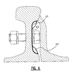
fig. 6 twochannels piece 63. - In the embodiment according to
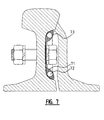
fig. 7 apart 71 which is relatively easy to manufacture is provided with twointernal channels - In the embodiment of
fig. 8 thechannels - In the embodiment according to
fig. 9 a relatively large channel is provided owing to aplate 92 which is welded to the top and bottom side of the rail. Owing to the form ofplate 101 the efficiency thereof per quantity of liquid is increased. Thechannel 111 according tofig. 11 can also be fixed to a rail in simple manner.Channels fig. 12 can be manufactured in relatively simple manner. - In the embodiment according to
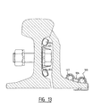
fig. 13 pipes orhoses fitting piece 105. Aspecial fitting piece 106 is also arranged on the base of the rail to accommodatechannels - In the embodiment according to
fig. 14 thechannels - In the above described embodiments it is recommended that the pipes are manufactured from a good conducting material at the position of the rails. This material is preferably a metal, wherein copper for instance has very good conducting properties and stainless steel for instance has excellent durability. Other metals or alloys can also be applied.
- The embodiment according to
fig. 15 comprises a ground loop with heat pump and heat exchanger. - The embodiment according to
fig. 16 is relatively simple in that it comprises a ground loop with heat pump having a relatively small number of components such as connectors and the like. - The embodiment according to
fig. 16 can be applied in a ground loop with heat exchanger and cooling agent, whereby higher temperatures differences can be achieved through evaporation and condensation thereof. - In the embodiment in which heat is extracted from the ground using one or more closed ground loops filled with a cold agent, this cold agent will begin to boil at relatively low temperature through pressure reduction on the primary side of the heat pump, whereby the pump will extract evaporation heat from the ground. On the secondary side of the heat pump the temperature of the liquid to the rail element will be increased.
- At the time of filing of the present invention work is still being done on the further development of the heating of movable rail elements such as crossing frogs and switch blades of switch points. It should however be apparent that the above described preferred embodiments can also be applied to such components of a rail system.
- Application of improved heat pumps which enable heating of water to 80 to 85° improves the temperature transfer even further.
- In order to prevent heat losses from rail elements, a further embodiment (
fig. 17 ) is provided with insulation means 131 which are fixed to the rail element by means of spring means 132. An alternative method of fixing the insulation means 131 to the rail element is the use ofbolt 133. Thisbolt 133 is used in the first instance to fixchannels channels thermal paste 136, whereby the heat of the liquid is conducted well to the rail element. This embodiment is further provided withliquid channels spring 139. A heat-conductingpaste 140 is likewise applied here. - There is the further possibility (not shown) of heat insulation being arranged over the liquid-carrying pipes of all embodiments. This has the advantage that heat is supplied in very specific manner to the rails and that heat losses are prevented, even while the heat is still located in the supply to the rails.
- The embodiments are very practicable and can be installed in existing rail and switch point systems.
- The present invention is not limited to the above described preferred embodiments thereof; the rights sought are defined by the following claims, within the scope of which many modifications can be envisaged.
Claims (20)
- System for heating or cooling a rail (11, 12, 24, 30) element, comprising said rail element and liquid guiding means that comprise a channel (14, 20, 21, 27) having one or more walls in heat-conductive contact with the rail element for the transfer of heat between the liquid and the rail element (11, 12, 24, 30), characterized in that, said channel (14, 20, 21, 27) connects to a conduit system (32), a part of which extends over a predetermined depth in the ground, whereby the channel and said conduit system (32) guide said liquid, so as to cause that heat respectively cold is extracted from the ground supporting said rail element.
- System according to claim 1, characterized in that, the channel (14, 20) is fixed to an upright part of the rail element.
- System according to claim 2, characterized in that the channel (21, 27) is fixed to a base (23, 29) of the rail element (24, 30).
- System according to any one of claims 1-3, characterized in that, the rail element (11, 12, 24, 30) forms one of the walls of the channel.
- System according to one the previous claims, characterized in that, a pump (36) is provided for the transfer of the liquid through the conduit system (32).
- System according to any one of claims 1-5, characterized in that it comprises a heat pump (49) in order to bring about an increase in the temperature of the liquid in the channels in addition to the heat absorbed from the ground.
- System according to any one of claim 1-6, characterized in that the channels are embodied as pipes or hoses (52, 53) with a form adapted to the rail element.
- System according to any one of claims 1-7, characterized in that the channels are fixed to the upright part of the rail element by use of paste (19) or welding to promote good heat transfer between the liquid in the channel (20) and the rail element.
- System according to any one of claims 1-8, characterized in that the web of the rail element and/or the channels and/or the conduit system is provided with insulation means.
- Method for heating and/or cooling a rail (11, 12, 24, 30) element, wherein heating liquid is carried along a channel (14, 20, 21, 27) guiding the liquid during transfer of the heat to or from the rail element, which channel is provided at least partly against at least an upright part (14, 20) of the rail element so as to cause that heat transfer takes place between the liquid and the rail element, characterized in that the relatively high temperature or low temperature of the liquid is obtained by extracting heat respectively cold from the ground by arranging pipes (33) for the liquid in the ground.
- Method as claimed in claim 10, wherein groundwater is pumped up to obtain the liquid of relatively high temperature.
- Method as claimed in claim 10 or 11, wherein the heat extracted from the ground is transferred to the liquid via a heat exchanger (44).
- Method as claimed in any of the claims 10-12, wherein use is made of a heat pump (49) to increase (or decrease) the temperature of the liquid.
- Method according to any one of claims 10-13, wherein the heat-exchanging surface between the liquid and the rail element is optimized by guiding the liquid through a channel (14, 20, 21, 27) having one or more walls in heat-conducting contact with the rail (11, 12, 24, 30) element.
- Method as claimed in claim 14, wherein at least one wall of the channel is formed by the rail element itself.
- Method as claimed in claim 14, wherein a pipe of substantially elongate cross-section is fixed along at least one long side thereof in heat-conducting manner to the rail element.
- Method as claimed in one or more of the foregoing claims 10-16, wherein insulation means are applied to prevent loss of heat energy from the rail element.
- Method as claimed in claim 17, wherein the insulation means are arranged substantially along the web of the rail element.
- Method as claimed in one or more of the claims 10-18, wherein for cooling purposes relatively cool liquid is extracted from the ground, to which cool liquid heat is supplied from hot rails.
- Method as claimed in claim 19, wherein this heated ground liquid is fed back again to the ground to be pumped up again later for reuse of the heat.
Applications Claiming Priority (2)
| Application Number | Priority Date | Filing Date | Title |
|---|---|---|---|
| NL1018204 | 2001-06-01 | ||
| NL1018204A NL1018204C2 (en) | 2001-06-01 | 2001-06-01 | Method and system for heating and / or cooling rails and rail element to be used thereby. |
Publications (3)
| Publication Number | Publication Date |
|---|---|
| EP1262597A2 EP1262597A2 (en) | 2002-12-04 |
| EP1262597A3 EP1262597A3 (en) | 2003-05-07 |
| EP1262597B1 true EP1262597B1 (en) | 2009-07-29 |
Family
ID=19773485
Family Applications (1)
| Application Number | Title | Priority Date | Filing Date |
|---|---|---|---|
| EP02077191A Expired - Lifetime EP1262597B1 (en) | 2001-06-01 | 2002-05-31 | Method and system for heating of rail and railelement for use therewith |
Country Status (5)
| Country | Link |
|---|---|
| EP (1) | EP1262597B1 (en) |
| AT (1) | ATE437996T1 (en) |
| DE (1) | DE60233091D1 (en) |
| DK (1) | DK1262597T3 (en) |
| NL (1) | NL1018204C2 (en) |
Cited By (6)
| Publication number | Priority date | Publication date | Assignee | Title |
|---|---|---|---|---|
| EP2366829A1 (en) | 2010-03-17 | 2011-09-21 | VolkerRail Nederland BV | Heating / cooling element for a railway switch |
| DE102013016232A1 (en) | 2013-10-01 | 2015-04-02 | Ean Elektroschaltanlagen Gmbh | Temperature control unit for track elements and system for controlling the temperature of track elements |
| RU2547666C1 (en) * | 2013-12-09 | 2015-04-10 | Дмитрий Викторович Герцик | Local heating device for railway tracks |
| RU2618577C1 (en) * | 2016-03-21 | 2017-05-04 | Федеральное государственное бюджетное образовательное учреждение высшего профессионального образования "Петербургский государственный университет путей сообщения Императора Александра I" | Heating system of railway turnouts in metallurgical production |
| WO2023285508A1 (en) | 2021-07-14 | 2023-01-19 | Bane Nor Sf | System for heating and/or cooling of a railway track |
| RU2846399C1 (en) * | 2024-05-03 | 2025-09-04 | Сергей Александрович Костенко | Road pavement thermal stabilization method |
Families Citing this family (10)
| Publication number | Priority date | Publication date | Assignee | Title |
|---|---|---|---|---|
| DE3025832A1 (en) | 1980-07-08 | 1982-02-04 | Dunham-Bush, Inc., 06110 West Hartford, Conn. | Air source heat pump system for heating buildings - has refrigerant charged bulb within air flow passing over outdoor coil for sensing ambient temp. |
| DK1529880T3 (en) | 2003-11-10 | 2016-12-05 | Wolfgang Feldmann | Heating arrangement for a railway switch |
| EP1645688A3 (en) * | 2004-10-06 | 2006-11-02 | Eugen Scharrenbroich | Heating device for a railway point |
| EP1813886A1 (en) * | 2006-01-26 | 2007-08-01 | Arcadis Consult GmbH | Method and apparatus for using thermal energy |
| DE102006012903B3 (en) * | 2006-03-17 | 2007-07-26 | Feldmann, Wolfgang, Dipl.-Ing. | Probe to gather heat from the ground, e.g. for heating road surfaces, has a number of tubes filled with a two-phase material to evaporate through ground heat to be carried out and condensed for heat delivery |
| ES2384602T3 (en) | 2008-03-07 | 2012-07-09 | Triple S Gmbh | Needle change heating system |
| EP2440706A1 (en) * | 2009-06-11 | 2012-04-18 | Balfour Beatty PLC | Arrangement for heating railroad switches |
| DE102009025107A1 (en) | 2009-06-11 | 2010-12-16 | Hermos Systems Gmbh | Method for controlling a point heating |
| EA029004B1 (en) | 2011-09-13 | 2018-01-31 | Трипл С-Гмбх | Switch heating system |
| NL2015359B1 (en) | 2014-08-28 | 2017-07-21 | Volkerrail Nederland Bv | Interchangeable frame chair with improved thermal contact. |
Family Cites Families (6)
| Publication number | Priority date | Publication date | Assignee | Title |
|---|---|---|---|---|
| FR1422242A (en) * | 1964-11-09 | 1965-12-24 | Comp Generale Electricite | Improvement in surface heating installations using electrical conductors |
| DE1277290B (en) * | 1966-05-06 | 1968-09-12 | Viktor Thiel | Point heating |
| JPS54149104A (en) * | 1978-05-12 | 1979-11-22 | Mitsubishi Electric Corp | Snow-melting de-icing device |
| DE3037721A1 (en) * | 1980-10-06 | 1982-05-13 | Oskar Dipl.-Ing. Dr.rer.nat. 8000 München Bschorr | Closed heater pipe containing volatile liq. - is inserted in ground as drill bit and heated by earth |
| IT8604823A0 (en) * | 1986-05-27 | 1986-05-27 | Plattner Franz | HEATING SYSTEM FOR THE THAWING OF RAILWAY POINTS BY CONDUCTING HEAT THROUGH HOT LIQUID. |
| RU1788117C (en) * | 1990-10-09 | 1993-01-15 | Институт технической механики АН УССР | Railway switch heater |
-
2001
- 2001-06-01 NL NL1018204A patent/NL1018204C2/en not_active IP Right Cessation
-
2002
- 2002-05-31 AT AT02077191T patent/ATE437996T1/en not_active IP Right Cessation
- 2002-05-31 DE DE60233091T patent/DE60233091D1/en not_active Expired - Lifetime
- 2002-05-31 DK DK02077191T patent/DK1262597T3/en active
- 2002-05-31 EP EP02077191A patent/EP1262597B1/en not_active Expired - Lifetime
Cited By (7)
| Publication number | Priority date | Publication date | Assignee | Title |
|---|---|---|---|---|
| EP2366829A1 (en) | 2010-03-17 | 2011-09-21 | VolkerRail Nederland BV | Heating / cooling element for a railway switch |
| DE102013016232A1 (en) | 2013-10-01 | 2015-04-02 | Ean Elektroschaltanlagen Gmbh | Temperature control unit for track elements and system for controlling the temperature of track elements |
| WO2015048939A1 (en) | 2013-10-01 | 2015-04-09 | Ean Elektroschaltanlagen Gmbh | Heating or cooling device for a rail profile element, operated by means of a heat pump |
| RU2547666C1 (en) * | 2013-12-09 | 2015-04-10 | Дмитрий Викторович Герцик | Local heating device for railway tracks |
| RU2618577C1 (en) * | 2016-03-21 | 2017-05-04 | Федеральное государственное бюджетное образовательное учреждение высшего профессионального образования "Петербургский государственный университет путей сообщения Императора Александра I" | Heating system of railway turnouts in metallurgical production |
| WO2023285508A1 (en) | 2021-07-14 | 2023-01-19 | Bane Nor Sf | System for heating and/or cooling of a railway track |
| RU2846399C1 (en) * | 2024-05-03 | 2025-09-04 | Сергей Александрович Костенко | Road pavement thermal stabilization method |
Also Published As
| Publication number | Publication date |
|---|---|
| DE60233091D1 (en) | 2009-09-10 |
| DK1262597T3 (en) | 2009-11-30 |
| EP1262597A2 (en) | 2002-12-04 |
| NL1018204C2 (en) | 2002-12-11 |
| EP1262597A3 (en) | 2003-05-07 |
| ATE437996T1 (en) | 2009-08-15 |
Similar Documents
| Publication | Publication Date | Title |
|---|---|---|
| EP1262597B1 (en) | Method and system for heating of rail and railelement for use therewith | |
| CA2684030C (en) | Heat transfer unit for heating systems and surfaces and railway point heater | |
| US20110114155A1 (en) | Solar energy use | |
| KR20110009102A (en) | Train heating system | |
| CN213277733U (en) | Transformer with good heat dissipation performance | |
| DK2756131T3 (en) | Turnout Heating System | |
| JP2013181676A (en) | Air conditioning system and air conditioning method | |
| CN105953426A (en) | Heat pump type large-temperature-difference heat supply method | |
| JP2015211619A (en) | Solar panel cooling/heating device | |
| EP3090213B1 (en) | Heat exchanger, heating device, heating system and method for heating water | |
| KR101683578B1 (en) | Solar heat and geothermy used a cooling and heating device | |
| KR101753152B1 (en) | A thermoelectric generator having heat exchanger using molten metal | |
| EP2484983B1 (en) | Operation method for micro-cogeneration system | |
| NL1022069C1 (en) | Heating and cooling method for train track rails, by passing liquid along rail side wall | |
| EA027643B1 (en) | Rail switch | |
| JP2013142491A (en) | Hot water supply and heating apparatus | |
| WO2011007224A2 (en) | Low cost, high thermal conductivity heat flux transporter | |
| CN208296361U (en) | A kind of refrigerating plant based on electrocaloric effect and field-synergy theory | |
| RU123014U1 (en) | ARROW HEATING SYSTEM | |
| CN219531344U (en) | Heat conduction structure of defrosting device | |
| JP4850118B2 (en) | Hot water supply piping heat insulation operation method in hot water storage type hot water supply system | |
| CN220235258U (en) | Energy storage cabinet air conditioner of water-cooling new energy equipment | |
| CN222733007U (en) | High-efficiency heating pipe of electric heating boiler | |
| CN223388769U (en) | Heat exchange assembly and refrigerator | |
| CN212463883U (en) | Efficient radiator, air conditioner frequency converter with efficient radiator and electronic equipment |
Legal Events
| Date | Code | Title | Description |
|---|---|---|---|
| PUAI | Public reference made under article 153(3) epc to a published international application that has entered the european phase |
Free format text: ORIGINAL CODE: 0009012 |
|
| AK | Designated contracting states |
Kind code of ref document: A2 Designated state(s): AT BE CH CY DE DK ES FI FR GB GR IE IT LI LU MC NL PT SE TR |
|
| AX | Request for extension of the european patent |
Free format text: AL;LT;LV;MK;RO;SI |
|
| PUAL | Search report despatched |
Free format text: ORIGINAL CODE: 0009013 |
|
| AK | Designated contracting states |
Designated state(s): AT BE CH CY DE DK ES FI FR GB GR IE IT LI LU MC NL PT SE TR |
|
| AX | Request for extension of the european patent |
Extension state: AL LT LV MK RO SI |
|
| 17P | Request for examination filed |
Effective date: 20030922 |
|
| AKX | Designation fees paid |
Designated state(s): AT BE CH CY DE DK ES FI FR GB GR IE IT LI LU MC NL PT SE TR |
|
| RAP1 | Party data changed (applicant data changed or rights of an application transferred) |
Owner name: MOVARES NEDERLAND B.V. |
|
| 17Q | First examination report despatched |
Effective date: 20070705 |
|
| GRAP | Despatch of communication of intention to grant a patent |
Free format text: ORIGINAL CODE: EPIDOSNIGR1 |
|
| GRAS | Grant fee paid |
Free format text: ORIGINAL CODE: EPIDOSNIGR3 |
|
| GRAA | (expected) grant |
Free format text: ORIGINAL CODE: 0009210 |
|
| AK | Designated contracting states |
Kind code of ref document: B1 Designated state(s): AT BE CH CY DE DK ES FI FR GB GR IE IT LI LU MC NL PT SE TR |
|
| REG | Reference to a national code |
Ref country code: GB Ref legal event code: FG4D |
|
| REG | Reference to a national code |
Ref country code: CH Ref legal event code: EP |
|
| REG | Reference to a national code |
Ref country code: IE Ref legal event code: FG4D |
|
| REF | Corresponds to: |
Ref document number: 60233091 Country of ref document: DE Date of ref document: 20090910 Kind code of ref document: P |
|
| REG | Reference to a national code |
Ref country code: SE Ref legal event code: TRGR |
|
| REG | Reference to a national code |
Ref country code: DK Ref legal event code: T3 |
|
| PG25 | Lapsed in a contracting state [announced via postgrant information from national office to epo] |
Ref country code: ES Free format text: LAPSE BECAUSE OF FAILURE TO SUBMIT A TRANSLATION OF THE DESCRIPTION OR TO PAY THE FEE WITHIN THE PRESCRIBED TIME-LIMIT Effective date: 20091109 Ref country code: AT Free format text: LAPSE BECAUSE OF FAILURE TO SUBMIT A TRANSLATION OF THE DESCRIPTION OR TO PAY THE FEE WITHIN THE PRESCRIBED TIME-LIMIT Effective date: 20090729 |
|
| PG25 | Lapsed in a contracting state [announced via postgrant information from national office to epo] |
Ref country code: PT Free format text: LAPSE BECAUSE OF FAILURE TO SUBMIT A TRANSLATION OF THE DESCRIPTION OR TO PAY THE FEE WITHIN THE PRESCRIBED TIME-LIMIT Effective date: 20091129 |
|
| PG25 | Lapsed in a contracting state [announced via postgrant information from national office to epo] |
Ref country code: BE Free format text: LAPSE BECAUSE OF FAILURE TO SUBMIT A TRANSLATION OF THE DESCRIPTION OR TO PAY THE FEE WITHIN THE PRESCRIBED TIME-LIMIT Effective date: 20090729 |
|
| PLBE | No opposition filed within time limit |
Free format text: ORIGINAL CODE: 0009261 |
|
| STAA | Information on the status of an ep patent application or granted ep patent |
Free format text: STATUS: NO OPPOSITION FILED WITHIN TIME LIMIT |
|
| 26N | No opposition filed |
Effective date: 20100503 |
|
| PG25 | Lapsed in a contracting state [announced via postgrant information from national office to epo] |
Ref country code: GR Free format text: LAPSE BECAUSE OF FAILURE TO SUBMIT A TRANSLATION OF THE DESCRIPTION OR TO PAY THE FEE WITHIN THE PRESCRIBED TIME-LIMIT Effective date: 20091030 |
|
| PG25 | Lapsed in a contracting state [announced via postgrant information from national office to epo] |
Ref country code: MC Free format text: LAPSE BECAUSE OF NON-PAYMENT OF DUE FEES Effective date: 20100531 |
|
| REG | Reference to a national code |
Ref country code: CH Ref legal event code: PL |
|
| PG25 | Lapsed in a contracting state [announced via postgrant information from national office to epo] |
Ref country code: CH Free format text: LAPSE BECAUSE OF NON-PAYMENT OF DUE FEES Effective date: 20100531 Ref country code: LI Free format text: LAPSE BECAUSE OF NON-PAYMENT OF DUE FEES Effective date: 20100531 |
|
| PG25 | Lapsed in a contracting state [announced via postgrant information from national office to epo] |
Ref country code: IT Free format text: LAPSE BECAUSE OF FAILURE TO SUBMIT A TRANSLATION OF THE DESCRIPTION OR TO PAY THE FEE WITHIN THE PRESCRIBED TIME-LIMIT Effective date: 20090729 |
|
| PG25 | Lapsed in a contracting state [announced via postgrant information from national office to epo] |
Ref country code: IE Free format text: LAPSE BECAUSE OF NON-PAYMENT OF DUE FEES Effective date: 20100531 |
|
| PGFP | Annual fee paid to national office [announced via postgrant information from national office to epo] |
Ref country code: DK Payment date: 20120516 Year of fee payment: 11 |
|
| PG25 | Lapsed in a contracting state [announced via postgrant information from national office to epo] |
Ref country code: CY Free format text: LAPSE BECAUSE OF FAILURE TO SUBMIT A TRANSLATION OF THE DESCRIPTION OR TO PAY THE FEE WITHIN THE PRESCRIBED TIME-LIMIT Effective date: 20090729 |
|
| PGFP | Annual fee paid to national office [announced via postgrant information from national office to epo] |
Ref country code: FR Payment date: 20120608 Year of fee payment: 11 Ref country code: GB Payment date: 20120522 Year of fee payment: 11 |
|
| PG25 | Lapsed in a contracting state [announced via postgrant information from national office to epo] |
Ref country code: LU Free format text: LAPSE BECAUSE OF NON-PAYMENT OF DUE FEES Effective date: 20100531 |
|
| PG25 | Lapsed in a contracting state [announced via postgrant information from national office to epo] |
Ref country code: TR Free format text: LAPSE BECAUSE OF FAILURE TO SUBMIT A TRANSLATION OF THE DESCRIPTION OR TO PAY THE FEE WITHIN THE PRESCRIBED TIME-LIMIT Effective date: 20090729 |
|
| PGFP | Annual fee paid to national office [announced via postgrant information from national office to epo] |
Ref country code: FI Payment date: 20130627 Year of fee payment: 12 |
|
| GBPC | Gb: european patent ceased through non-payment of renewal fee |
Effective date: 20130531 |
|
| REG | Reference to a national code |
Ref country code: DK Ref legal event code: EBP Effective date: 20130531 |
|
| REG | Reference to a national code |
Ref country code: FR Ref legal event code: ST Effective date: 20140131 |
|
| PG25 | Lapsed in a contracting state [announced via postgrant information from national office to epo] |
Ref country code: DK Free format text: LAPSE BECAUSE OF NON-PAYMENT OF DUE FEES Effective date: 20130531 Ref country code: GB Free format text: LAPSE BECAUSE OF NON-PAYMENT OF DUE FEES Effective date: 20130531 |
|
| PG25 | Lapsed in a contracting state [announced via postgrant information from national office to epo] |
Ref country code: FR Free format text: LAPSE BECAUSE OF NON-PAYMENT OF DUE FEES Effective date: 20130531 |
|
| PGFP | Annual fee paid to national office [announced via postgrant information from national office to epo] |
Ref country code: SE Payment date: 20140530 Year of fee payment: 13 Ref country code: NL Payment date: 20140526 Year of fee payment: 13 |
|
| PG25 | Lapsed in a contracting state [announced via postgrant information from national office to epo] |
Ref country code: FI Free format text: LAPSE BECAUSE OF NON-PAYMENT OF DUE FEES Effective date: 20140531 |
|
| REG | Reference to a national code |
Ref country code: SE Ref legal event code: EUG |
|
| REG | Reference to a national code |
Ref country code: NL Ref legal event code: MM Effective date: 20150601 |
|
| PG25 | Lapsed in a contracting state [announced via postgrant information from national office to epo] |
Ref country code: SE Free format text: LAPSE BECAUSE OF NON-PAYMENT OF DUE FEES Effective date: 20150601 |
|
| PG25 | Lapsed in a contracting state [announced via postgrant information from national office to epo] |
Ref country code: NL Free format text: LAPSE BECAUSE OF NON-PAYMENT OF DUE FEES Effective date: 20150601 |
|
| PGFP | Annual fee paid to national office [announced via postgrant information from national office to epo] |
Ref country code: DE Payment date: 20170530 Year of fee payment: 16 |
|
| REG | Reference to a national code |
Ref country code: DE Ref legal event code: R119 Ref document number: 60233091 Country of ref document: DE |
|
| PG25 | Lapsed in a contracting state [announced via postgrant information from national office to epo] |
Ref country code: DE Free format text: LAPSE BECAUSE OF NON-PAYMENT OF DUE FEES Effective date: 20181201 |