EP1265025A2 - Leuchte mit einer Entladunslampe und einem strukturierten Reflektor - Google Patents
Leuchte mit einer Entladunslampe und einem strukturierten Reflektor Download PDFInfo
- Publication number
- EP1265025A2 EP1265025A2 EP02012082A EP02012082A EP1265025A2 EP 1265025 A2 EP1265025 A2 EP 1265025A2 EP 02012082 A EP02012082 A EP 02012082A EP 02012082 A EP02012082 A EP 02012082A EP 1265025 A2 EP1265025 A2 EP 1265025A2
- Authority
- EP
- European Patent Office
- Prior art keywords
- elevations
- depressions
- lines
- section
- luminaire according
- Prior art date
- Legal status (The legal status is an assumption and is not a legal conclusion. Google has not performed a legal analysis and makes no representation as to the accuracy of the status listed.)
- Granted
Links
- 238000000149 argon plasma sintering Methods 0.000 claims description 13
- 239000000463 material Substances 0.000 claims description 13
- 230000008859 change Effects 0.000 claims description 7
- 230000000630 rising effect Effects 0.000 claims description 4
- 238000005452 bending Methods 0.000 claims 2
- 239000002184 metal Substances 0.000 claims 1
- 238000004519 manufacturing process Methods 0.000 description 6
- 239000006059 cover glass Substances 0.000 description 3
- 238000000034 method Methods 0.000 description 3
- 230000000295 complement effect Effects 0.000 description 2
- 239000011521 glass Substances 0.000 description 2
- 230000007246 mechanism Effects 0.000 description 2
- 229910001507 metal halide Inorganic materials 0.000 description 2
- 150000005309 metal halides Chemical class 0.000 description 2
- 230000000737 periodic effect Effects 0.000 description 2
- 241000842962 Apoda limacodes Species 0.000 description 1
- DGAQECJNVWCQMB-PUAWFVPOSA-M Ilexoside XXIX Chemical compound C[C@@H]1CC[C@@]2(CC[C@@]3(C(=CC[C@H]4[C@]3(CC[C@@H]5[C@@]4(CC[C@@H](C5(C)C)OS(=O)(=O)[O-])C)C)[C@@H]2[C@]1(C)O)C)C(=O)O[C@H]6[C@@H]([C@H]([C@@H]([C@H](O6)CO)O)O)O.[Na+] DGAQECJNVWCQMB-PUAWFVPOSA-M 0.000 description 1
- 230000015572 biosynthetic process Effects 0.000 description 1
- 239000000919 ceramic Substances 0.000 description 1
- 230000007423 decrease Effects 0.000 description 1
- 238000009826 distribution Methods 0.000 description 1
- 230000000694 effects Effects 0.000 description 1
- 238000007373 indentation Methods 0.000 description 1
- 238000002347 injection Methods 0.000 description 1
- 239000007924 injection Substances 0.000 description 1
- 230000001788 irregular Effects 0.000 description 1
- 238000003825 pressing Methods 0.000 description 1
- 230000008569 process Effects 0.000 description 1
- 239000004576 sand Substances 0.000 description 1
- 230000035939 shock Effects 0.000 description 1
- 229910052708 sodium Inorganic materials 0.000 description 1
- 239000011734 sodium Substances 0.000 description 1
- 230000007480 spreading Effects 0.000 description 1
- 238000003892 spreading Methods 0.000 description 1
- 230000007704 transition Effects 0.000 description 1
Images


Classifications
-
- F—MECHANICAL ENGINEERING; LIGHTING; HEATING; WEAPONS; BLASTING
- F21—LIGHTING
- F21V—FUNCTIONAL FEATURES OR DETAILS OF LIGHTING DEVICES OR SYSTEMS THEREOF; STRUCTURAL COMBINATIONS OF LIGHTING DEVICES WITH OTHER ARTICLES, NOT OTHERWISE PROVIDED FOR
- F21V7/00—Reflectors for light sources
- F21V7/04—Optical design
-
- F—MECHANICAL ENGINEERING; LIGHTING; HEATING; WEAPONS; BLASTING
- F21—LIGHTING
- F21W—INDEXING SCHEME ASSOCIATED WITH SUBCLASSES F21K, F21L, F21S and F21V, RELATING TO USES OR APPLICATIONS OF LIGHTING DEVICES OR SYSTEMS
- F21W2131/00—Use or application of lighting devices or systems not provided for in codes F21W2102/00-F21W2121/00
- F21W2131/10—Outdoor lighting
- F21W2131/105—Outdoor lighting of arenas or the like
Definitions
- the invention relates to a lamp according to the preamble of claim 1.
- Luminaires are used in particular to illuminate large areas of squares and sports facilities used.
- the reflector of the luminaire focuses the light directs certain sections to be illuminated, that is, distributes the light from the lamp in a directed manner. This is only possible in a satisfactory manner if the lamp or the illuminating one Section of the lamp is positioned very precisely and the mirror is made very precisely.
- Many high-pressure discharge lamps do not. For example, with discharge lamps in sofa form, e.g.
- HQI-TS lamps from Osram or MHD, MHD-TD, MHN-SA or MHN-TD from Philips, a clear discharge vessel provided, which has the shape of a sphere, an ellipsoid or a similar shape in which a Arc is generated between two electrodes. The location of this arc can change change in operation, so that accordingly the area that is illuminated by the lamp will change, resulting in illuminance unevenness on the illuminated Surface can lead.
- discharge lamps in the form of tubes e.g. of the type NAV-T or HCI-T from Osram or type SON-T or CDM-TT from Philips, is a matt Small diameter tubular discharge vessel installed in a clear outer bulb.
- This discharge vessel in the outer bulb is subject to manufacturing tolerances, which have a noticeable effect on the light emission characteristics of the luminaire, that the reflector is not optimally matched to the lamp.
- Other sources of error are in manufacturing tolerances of the reflector and tolerances of the socket as well as in shape changes due to the heat generated by the lamp or changes in the position of the discharge vessel due to vibrations. In many cases it is also undesirable to use the high one Show the luminance of the arc or the discharge vessel.
- the reflector was constructed from high-gloss facets. This had the disadvantage, however, that the degree of light scattering is the size of the facets depended and the bundling of light was not completely satisfactory when the facets were so dimensioned that errors in the position of the lamp were compensated. in addition came that faceted reflectors are sensitive to thermal deformation.
- this object is achieved by a luminaire with a discharge lamp, in particular a high-pressure discharge lamp, and a reflector, which light the Lamp reflected to a light exit opening, so that a fixed in relation to the lamp Area is illuminated, with the reflector the light falling on it predominantly directionally reflected and at least in a partial section of a reflective one Surface has a regular, partially light-scattering structure, the light partially scattering structure has elevations and / or depressions and by one or more Lines are defined, each of which the ridge of the elevations or the bottom of the depressions follows, in a cross section along the surface, in particular a plane, transversely to the structure or the lines defining the structure, the structure is a sequence of successive Has elevations and / or depressions, which are usually spaced apart are.
- the area of an elevation or Deepening can be viewed as the area between two turning points of the contour where the second derivative is zero.
- the structure has a regular sequence of surveys and / or depressions which lead to a scattering of the light.
- the structure can in particular be designed periodically.
- the period with which the structure repeated, does not necessarily have only one elevation and an intermediate section exhibit.
- Structures are also possible in which one period has several Has elevations, depressions and / or intermediate sections of different widths then repeat themselves within the structure.
- According to an embodiment of the invention shows the structure in a section along the surface perpendicular to those defining the structure Lines of bumps or depressions of the same width, through the flat or to the general reflector contour adapted sections are separated.
- periodic Structures conceivable, such as structures in which one or more parameters, e.g. the width of the elevations or depressions or their angle of inclination to adjacent Areas change according to a predetermined law, such as that the angle of attack and / or the width with increasing distance from the lamp according to one predetermined function increases or decreases.
- the structure is arranged in relation to the lamp so that both flanks an elevation and / or depression reflect light directly incident on it from the lamp.
- the invention can provide that the discharge lamp has a discharge vessel in a clear Has outer bulb or a clear discharge vessel.
- the invention can provide that the lamp is of a type in which the arc of the Discharge lamp can change its position during operation.
- the invention finds a particularly advantageous application in lights in which the Lamp has a tubular shape and has a discharge vessel, the location of which in one Outer bulb has a relatively high tolerance in relation to its dimensions (e.g. one Tolerance according to DIN EN 60662, which i.a. an inclination of the axis of the discharge vessel the base axis of up to 3 °) and / or its position sensitive to Shocks is.
- the position of this discharge vessel in the outer bulb can be do not control precisely during production and are also sensitive to vibrations.
- the invention can provide that the lamp is a metal halide lamp, e.g. a metal halide lamp or is a high pressure sodium lamp.
- a metal halide lamp e.g. a metal halide lamp or is a high pressure sodium lamp.
- the invention can provide that the structure on a light at least essentially directed reflective surface, in particular a specularly reflective surface is trained.
- the invention produces the reflective surface of the reflector provided structure some degree of controlled spreading which tolerances the position of the discharge vessel with respect to the reflector and / or changes in position of the arc compensated.
- the invention can provide that the surface on which the structure is formed is high-gloss is.
- the invention can provide that the elevations and / or the depressions or the areas formed between them in the form of adjacent, spaced strips are.
- the invention can provide that the lines that define the structure are at least aligned do not cut on said section of the reflecting surface of the reflector.
- the lines that define the structure are essentially parallel, i.e. the lines have essentially the same course, whereby the distance between the lines according to certain embodiments along the Lines also changes.
- the lines are parallel, i.e. they are always the same distance apart.
- the angle between these lines is less than 90 °, preferably less than 40 °.
- curved lines can have similar relationships regarding the tangents to these lines be provided.
- an angle of less than 90 ° preferably one Includes angles of less than 40 °.
- the invention can provide that one or more lines defining the structure Are geodesists. Geodesists are lines on any surface, which is the shortest connection define two points. On one level, the geodesics are degrees.
- the Structure can be defined by a single spiral line, which is the ridge, i.e. the maximum a survey or the reason, i.e. a minimum, follows a deepening.
- One or several lines that define the structure can also be self-contained and for example, have a circular or elliptical shape, the circle or the ellipse then preferably extends over the entire circumference of the reflector.
- the closed lines that define the structure are concentric to each other.
- the invention can provide that for at least one, preferably the majority, particularly all bumps and / or depressions of the structure prefer the width of the bump and / or the deepening of the structure and / or for at least one pair of elevations and / or depressions, preferably the majority of such pairs, in particular all such Pairs, the width of an area between two adjacent elevations or depressions or between an elevation and a depression of the structure adjacent to the elevation is in a range from 0.5 d to 2 d.
- d is the diameter of the discharge vessel or the discharge arc of the discharge lamp, depending on whether the glowing, directly visible section of the lamp is defined by the discharge vessel or the arc.
- the width of the elevation or depression is defined by the distance between the points at which these, usually in the form of an edge, adjoin the interface.
- the width of the elevation or depression is provided by the distance between the turning points to both Sides of the maximum of the elevation or the minimum of the deepening.
- the mean or maximum Structure width of the structure measured between two adjacent maxima or minima of the Structure, between 1 d and 4 d, where d is the diameter of the discharge vessel or of the discharge arc of the discharge lamp.
- the invention can provide that the diameter of the burner of the discharge lamp between 1 mm and 10 mm, in particular 1 mm to 8 mm.
- the structure width is with a structure with parallel lines approx. 4 mm.
- the invention can provide that the structure in a section along a surface transversely, in particular perpendicular to the line or lines, a substantially flat section between has two triangular elevations. If the reflector surface, what is the rule is not flat, but is curved, is also the area between the triangular As a rule, surveys are not flat, but according to the general reflector contour curved. The corresponding structure can result from the fact that a flat sheet with a section between the triangular elevations is bent, the Manufacture the same structure, as will be explained below, with other methods leaves.
- the invention can provide that the structure in a section along a surface transversely, in particular perpendicular to the line or lines, a substantially flat section between has two elevations trapezoidal in cross section.
- a curved reflector surface is the section between the surveys usually according to the general Reflector contour curved; the above applies accordingly.
- the invention can provide that the width of the elevations or depressions, measured in the direction perpendicular to the lines, approximately equal to the width of the flat or corresponding the general reflector contour is curved section, this width preferably is in a range between 0.5 d and 2 d, where d is the diameter of the discharge vessel or the discharge arc of the discharge lamp.
- the invention can provide that the structure is perpendicular in a section along a surface to the line or lines a smooth, wavy, especially sinusoidal Has history.
- the invention can provide that in a section along a surface perpendicular to the or the lines the maximum angle of a tangent to a rising flank of an elevation to a tangent to an adjacent minimum of the structure, especially a flat one or according to the general reflector contour curved area between two elevations, in a range from 1 ° to 10 °, particularly preferably 1.5 ° to 3.5 °, in particular 2.5 °, the smaller angle being the angle between the tangents.
- the invention can provide that in a section along a surface perpendicular to the or the lines of the angle between a flat flank of an elevation of the structure and the adjacent flat or curved surface according to the general reflector contour is between 170 ° and 179 °.
- the reflector of the lamp can in particular be formed in a channel shape.
- the invention also provides a method of making a reflector with a straight line Structure as described above available, characterized in that a Material with a rectilinear structure formed into a reflector, in particular rolled becomes.
- the invention can also provide that the reflector is made of a high-gloss material is pressed, the structure being impressed into the material during the pressing process. This method is particularly useful for rotationally symmetrical or cup-shaped reflectors advantageous.
- FIG. 1 to 3 show the schematic structure of an embodiment of an inventive Luminaire in the form of an asymmetrical floodlight.
- Fig. 1 shows a Side view.
- Reference numeral 6 denotes the lamp housing, 8 represents a cover.
- the lamp is attached to a support bracket 10 via a swivel mechanism 12.
- the Light exit opening of the lamp points downwards in FIG. 1.
- a cover glass 14 (Fig. 2) is mounted in front of the light outlet opening.
- Fig. 2 shows the same lamp in the direction of the light exit opening. Behind the End glass 14 are the reflector 16 and the lamp 18. In the representation of Fig. 2, a frame 20 is also shown, which represents a cover of the end glass 14 which for example, is applied to the cover glass by printing.
- the exemplary embodiment shows a discharge lamp in the form of a festoon, which is spherical Discharge vessel in which an arc generated between two electrodes becomes.
- a discharge lamp in the form of a festoon, which is spherical Discharge vessel in which an arc generated between two electrodes becomes.
- lamps of the type HQI - TS, MHD, MHD - TD, MHN-SA or Act MHN - TD can also Discharge lamps in the form of tubes, e.g. of the type NAV - T, SON - T, CDM -TT or HCI-T be provided.
- the lamp 18 is positioned so that the arc or the discharge vessel Lamp 18 is ideally located in the focus of the reflector 16.
- the position of the arc However, even with precise positioning of the lamp 18, it can actually be outside the Focus, since the position of the arc or the discharge vessel is during the operation of the discharge lamp can change.
- Another reason for the relocation of the arc or the discharge vessel particularly in the case of versions with discharge lamps in tube form, can also in the manufacturing tolerances regarding the location of the Discharge vessel be established in the discharge lamp.
- the location of the Shift and / or widen the focus of the reflector 16 during operation for example by thermal or mechanical deformation of the reflector.
- the reflector 16 basically has the shape in a section along the line A-A in FIG. 2 of an asymmetrical parabolic section. In the perpendicular section along the Line B-B, the reflector 16 is shaped substantially flat.
- the reflector surface has According to the invention, a structure running along lines on the surface, which is shown in FIG. 2 is indicated by dashed lines and the following with reference to FIGS. 6 to 8 in more detail is explained. The lines along which the structure runs can also be different than in Fig. 2 indicated, e.g. perpendicular to the lamp axis.
- Fig. 3 shows the rear view of the lamp, with the components already described above are identified by the same reference numerals.
- the shape of the lamp and in particular the reflector is not based on that shown in FIGS. 1 to 3 Forms limited. Rather, other reflector shapes are also possible in particular, e.g. in the form of a paraboloid of revolution.
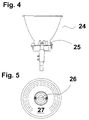
- An embodiment of an inventive Luminaire with a rotationally symmetrical reflector is shown in FIGS. 4 and 5.
- a rotationally symmetrical reflector 24 the wall of which in a cross section through the axis of symmetry and perpendicular to the light exit surface the shape of two parabolic sections, placed on a housing 25, which has a sofitteniform Lamp 26 which is symmetrical with respect to the axis of symmetry of the reflector is arranged and ideally lies in the focal point of the parabola section, which is the contour the wall.
- the inner wall 27 of the reflector has a linear structure provided, which is indicated in Fig. 5 by dashed lines. While indicated in Fig. 5 lines are concentric circles to the axis of symmetry of the reflector can a different course of the lines can also be provided, for example a radial course of the end of the reflector facing the lamp 26 to the light exit opening.
- FIGS. 6 to 8 each show a section of a cross section of different embodiments of the reflector of the lamp according to the invention along a surface transverse to the or the lines defining the structure of the reflector, this being the same for the reflector 16 of the embodiment according to FIGS. 1 to 3 and for the reflector 24 of the 4 and 5 applies.
- the drawings are of simplicity only the reference numerals for the first embodiment shown in FIGS. 1 to 3 are given.
- the reflector 16 or 24 has a mirrored, light-reflecting surface 22 or 27 with structured sections 30 and intermediate flat sections 32, the curvature of which follows the general shape of the reflector.
- the structured sections 30 running along lines have the shape of an isosceles triangle with the width D 1 in cross section.
- the pitch angle S of the triangular flanks is in the range between 1 ° to 10 °, particularly preferably between 1.5 ° to 3.5 °, in particular 2.5 °. Accordingly, the angle between the flat section and this flank (180 ° -S) is between 170 ° and 179 °, particularly preferably between 176.5 ° and 178.5 °, in particular 177.5 °.
- the light beams incident parallel on the flanks 30a and 30b are reflected at an expansion angle of 4S.
- These sections 30 therefore represent the light-scattering elements of the structure of the reflector 16.
- the sections 30 preferably have a width D 1 between 0.5 d to 2 d, where d is the diameter of the discharge vessel or the discharge arc of the discharge lamp.
- the substantially planar surface sections 32 of the reflector reflect the light in a substantially directed manner in accordance with the target characteristic of the reflector.
- the sections 30 produce a scattering for this target characteristic, which compensates for tolerances in the position of the arc of the lamp 18.
- the light-scattering sections 30 running along lines can be parallel to one another with a preferred distance of 0.5 d to 2 d, which corresponds to the width D 2 of the section 32 in this exemplary embodiment. Other arrangements are also possible.
- FIG. 7 shows a section of the cross section of a reflector of an exemplary embodiment of the present invention, in which the light-scattering sections 34 of the reflector surface 22 have the shape of a trapezoid in cross section.
- the pitch angle S of the trapezoidal flanks is in the range between 1 ° to 10 °, particularly preferably between 1.5 ° to 3.5 °, in particular 2.5 °.
- Light rays incident parallel on the flanks 34a and 34b are reflected at an expansion angle of 4S.
- These sections 34 therefore represent the light-scattering elements of the structure of the reflector 16.
- the sections 34 preferably have a width D 3 between 0.5 d to 2 d, where d is the diameter of the discharge vessel or of the discharge arc of the discharge lamp.
- the substantially flat surface portions 32 of the reflector reflect the light in a generally directed manner.
- the light-scattering sections 34 running along lines can be parallel to one another with a preferred distance of 0.5 d to 2 d, which corresponds to the width D 2 of the section 32 in this exemplary embodiment. Other arrangements are also possible.
- Fig. 8 shows the cross section of a reflector with a wave-like profile with elevations 38 and depressions 40.
- the maximum pitch angle S at the turning points between The elevations 38 and depressions 40 are in the preferred embodiment in the range between 1 ° to 10 °, particularly preferably between 1.5 ° to 3.5 °, in particular at 2.5 °.
- the Sections of the elevations 38 and the depressions 40 each between two successive ones Inflection points of the waves have an extension perpendicular to that of the structure defining lines preferably between 0.5 d to 2 d.
- Both the sections 38 and 40 of the luminaire according to the invention contribute to the scatter of the light.
- the largest scattering angle is caused by light rays that are in the area the maximum slope at the turning points of the wave structure are reflected.
- the expansion range is 4S; at the flatter areas, the light rays in the essentially directed reflected.
- the surface areas of the reflector for example the areas 32 in which the directional reflection takes place, preferably a high-gloss mirror material used; but preferably the entire reflector surface consists of a high-gloss Material.
- a material can be used to produce the reflectors, such as from EP 0 892 288 A1, which already has the linear structures. Trials have been special good results, for example with a high gloss material "Softgloss” 720 the Alanod company with wave-like profiling with a maximum pitch angle of approx. 2.5 ° and a structure width of approx. 4 mm. From the material structured in this way the reflector be continuously curved, the direction of curvature being preferred for technical reasons along or across the straight structure, but also can be done arbitrarily.
- For rotationally symmetrical floodlights are usually parabolic (conical) mirror pots made of high-gloss materials pressed. Here you can Partial light-scattering structure mentioned above on the existing form of continuous curved mirror can also be embossed.
- the The partial light-scattering structure described above is taken into account in the injection molds become.
- the surface is then coated with a high-gloss finish.
- the sequence of Elevations and depressions in a cross section perpendicular to the lines that the Define structure can be periodic or statistical.
- n Depressions are provided, where n is a natural number, or where, more generally, on m Surveys follow n depressions, where m and n are natural numbers. It's also more complicated in particular, statistical sequences are also possible.
Landscapes
- Engineering & Computer Science (AREA)
- General Engineering & Computer Science (AREA)
- Non-Portable Lighting Devices Or Systems Thereof (AREA)
- Optical Elements Other Than Lenses (AREA)
Abstract
Description
- 6
- Leuchtengehäuse
- 8
- Abdeckgehäuse für elektrische Bauteile
- 10
- Traghalter
- 12
- Schwenkmechanismus
- 14
- Abschlußglas
- 16
- Reflektor
- 18
- Lampe
- 20
- Abdeckung
- 22
- reflektierende Oberfläche
- 24
- Reflektor
- 25
- Gehäuse
- 26
- Lampe
- 27
- reflektierende Oberfläche
- 30
- Licht streuender Abschnitt im Dreiecksform
- 30a
- absteigende Flanke
- 30b
- ansteigende Flanke
- 32
- Licht gerichtet reflektierender Abschnitt
- 34
- Licht streuender Abschnitt in Trapezform
- 34a
- ansteigende Flanke
- 34b
- absteigende Flanke
- 38
- Erhebung der Wellenstruktur
- 40
- Vertiefung der Wellenstruktur
Claims (17)
- Leuchte mit einer Hochdruck-Entladungslampe (18) sowie einem Reflektor (16), welcher Licht der Lampe zu einer Lichtaustrittsöffnung reflektiert, wobei der Reflektor (16) zumindest in einem Teilabschnitt einer reflektierenden Fläche eine teilweise Licht streuende Struktur mit Erhebungen und/oder Vertiefungen aufweist, dadurch gekennzeichnet, daß die teilweise Licht streuende Struktur regelmäßig ausgebildet ist und durch eine oder mehrere Linien definiert ist, denen jeweils der Grat der Erhebungen bzw. der Grund der Vertiefungen folgt, wobei in einem Querschnitt entlang einer Fläche quer zu der bzw. den die Struktur definierenden Linien die Struktur eine Abfolge von aufeinanderfolgenden Erhebungen und/oder Vertiefungen aufweist.
- Leuchte nach Anspruch 1, dadurch gekennzeichnet, daß die Entladungslampe (18) ein Entladungsgefäß in einem klaren Außenkolben oder ein klares Entladungsgefäß ohne Hüllkolben aufweist.
- Leuchte nach Anspruch 1 oder 2, dadurch gekennzeichnet, daß die Lampe von einem Typ ist, bei dem der Lichtbogen der Entladungslampe (18) im Betrieb seine Lage ändern kann.
- Leuchte nach Anspruch 2 oder 3, dadurch gekennzeichnet, daß die Lampe eine Metalldampflampe ist.
- Leuchte nach einem der Ansprüche 1 bis 4, dadurch gekennzeichnet, daß die Oberfläche, auf der die Struktur ausgebildet ist, Licht zumindest im wesentlichen gerichtet reflektiert.
- Leuchte nach einem der Ansprüche 1 bis 5, dadurch gekennzeichnet, daß die Oberfläche, auf der die Struktur ausgebildet ist, hochglänzend ist.
- Leuchte nach einem der Ansprüche 1 bis 6, dadurch gekennzeichnet, daß die Erhebungen und/oder die Vertiefungen in der Form von nebeneinander liegenden Streifen ausgebildet sind.
- Leuchte nach einem der Ansprüche 1 bis 7, dadurch gekennzeichnet, daß die Linien, welche die Struktur definieren, parallel zueinander sind.
- Leuchte nach einem der Ansprüche 1 bis 8, dadurch gekennzeichnet, daß die Breite der Erhebungen bzw. Vertiefungen und/oder die Breite der Bereiche zwischen zwei benachbarten Erhebungen bzw. Vertiefungen der Struktur 0,5 d bis 2 d beträgt, wobei d der Durchmesser des Entladungsgefäßes oder des Lichtbogens der Entladungslampe (18) ist.
- Leuchte nach Anspruch 9, dadurch gekennzeichnet, daß die Breite der Erhebungen bzw. Vertiefungen und/oder die Breite der Bereiche zwischen zwei benachbarten Erhebungen bzw. Vertiefungen der Struktur zwischen 0,5 mm und 20 mm liegt.
- Leuchte nach einem der Ansprüche 1 bis 10, dadurch gekennzeichnet, daß der Durchmesser des Entladungsgefäßes der Entladungslampe (18) zwischen 1 mm und 10 mm liegt.
- Leuchte nach einem der Ansprüche 1 bis 11, dadurch gekennzeichnet, daß der Teilabschnitt eine Struktur aufweist, die in einem Schnitt entlang einer Fläche quer zu der oder den Linien einen im wesentlichen ebenen Abschnitt (32) zwischen zwei aufeinanderfolgenden dreiecksförmigen Erhebungen (30) und/oder Vertiefungen aufweist, oder die durch Biegen eines ebenen Materials mit einer linienförmigen Struktur, die in einem Schnitt entlang einer Fläche quer zu der oder den Linien jeweils einen im wesentlichen ebenen Abschnitt zwischen zwei aufeinanderfolgenden dreiecksförmigen Erhebungen (30) und/oder Vertiefungen aufweist, erhältlich ist.
- Leuchte nach einem der Ansprüche 1 bis 11, dadurch gekennzeichnet, daß der Teilabschnitt eine Struktur aufweist, die in einem Schnitt entlang einer Fläche quer zu der oder den Linien einen im wesentlichen ebenen Abschnitt (32) zwischen zwei aufeinanderfolgenden, im Querschnitt trapezförmigen Erhebungen (34) und/oder Vertiefungen aufweist, oder die durch Biegen eines ebenen Materials mit einer linienförmigen Struktur, die in einem Schnitt entlang einer Fläche quer zu der oder den Linien jeweils einen im wesentlichen ebenen Abschnitt (32) zwischen zwei im Querschnitt trapezförmigen aufeinanderfolgenden Erhebungen (34) und/oder Vertiefungen aufweist, erhältlich ist.
- Leuchte nach Anspruch 12 oder 13, dadurch gekennzeichnet, daß die Breite der Erhebungen und/oder Vertiefungen ungefähr gleich der Breite des Abschnitts (32) zwischen zwei aufeinanderfolgenden Erhebungen bzw. Vertiefungen ist.
- Leuchte nach einem der Ansprüche 1 bis 11, dadurch gekennzeichnet, daß die Struktur in einem Schnitt entlang einer Fläche senkrecht zu der oder den Linien einen glatten, wellenartigen Verlauf aufweist.
- Leuchte nach einem der Ansprüche 1 bis 15, dadurch gekennzeichnet, daß in einem Schnitt entlang einer Fläche quer zu der oder den Linien der maximale Winkel (S) einer Tangente an eine ansteigenden Flanke einer Erhebung zu einer Tangente an ein benachbartes Minimum der Struktur oder an einen ebenen bzw. an die allgemeine Reflektorkontur angepaßten Abschnitt, der unmittelbar an die Erhebung anschließt, in einen Bereich von 1° bis 10° liegt.
- Leuchte nach einem der Ansprüche 11 bis 14, dadurch gekennzeichnet, daß in einem Schnitt entlang einer Fläche senkrecht zu der oder den Linien der Winkel (180° - S) zwischen einer Flanke einer Erhebung der Struktur und der benachbarten, ebenen Fläche bzw. der entsprechend der allgemeinen Reflektorkontur gebogenen Fläche zwischen 170° und 179° liegt.
Applications Claiming Priority (2)
| Application Number | Priority Date | Filing Date | Title |
|---|---|---|---|
| DE10127332 | 2001-06-06 | ||
| DE10127332 | 2001-06-06 |
Publications (3)
| Publication Number | Publication Date |
|---|---|
| EP1265025A2 true EP1265025A2 (de) | 2002-12-11 |
| EP1265025A3 EP1265025A3 (de) | 2005-08-24 |
| EP1265025B1 EP1265025B1 (de) | 2007-12-05 |
Family
ID=7687301
Family Applications (1)
| Application Number | Title | Priority Date | Filing Date |
|---|---|---|---|
| EP02012082A Expired - Lifetime EP1265025B1 (de) | 2001-06-06 | 2002-05-31 | Leuchte mit einer Entladunslampe und einem strukturierten Reflektor |
Country Status (3)
| Country | Link |
|---|---|
| EP (1) | EP1265025B1 (de) |
| AT (1) | ATE380317T1 (de) |
| DE (1) | DE50211304D1 (de) |
Cited By (1)
| Publication number | Priority date | Publication date | Assignee | Title |
|---|---|---|---|---|
| EP1900998A1 (de) | 2006-09-15 | 2008-03-19 | Siteco Beleuchtungstechnik GmbH | Reflektor mit einer lichtaufweisenden Struktur |
Citations (1)
| Publication number | Priority date | Publication date | Assignee | Title |
|---|---|---|---|---|
| EP0892288A1 (de) | 1997-07-17 | 1999-01-20 | Alusuisse Technology & Management AG | Walzprodukt aus Metall mit lichtaufweitender Oberflächenstruktur |
Family Cites Families (4)
| Publication number | Priority date | Publication date | Assignee | Title |
|---|---|---|---|---|
| JPS5684805A (en) * | 1979-12-11 | 1981-07-10 | Toshiba Electric Equip | Illuminator |
| NL186466C (nl) * | 1980-07-28 | 1992-03-16 | Philips Nv | Verlichtingsarmatuur. |
| NL192273C (nl) * | 1986-12-04 | 1997-04-03 | Philips Electronics Nv | Verlichtingsarmatuur. |
| US6203176B1 (en) * | 1998-12-14 | 2001-03-20 | Musco Corporation | Increased efficiency light fixture, reflector, and method |
-
2002
- 2002-05-31 DE DE50211304T patent/DE50211304D1/de not_active Expired - Lifetime
- 2002-05-31 EP EP02012082A patent/EP1265025B1/de not_active Expired - Lifetime
- 2002-05-31 AT AT02012082T patent/ATE380317T1/de active
Patent Citations (1)
| Publication number | Priority date | Publication date | Assignee | Title |
|---|---|---|---|---|
| EP0892288A1 (de) | 1997-07-17 | 1999-01-20 | Alusuisse Technology & Management AG | Walzprodukt aus Metall mit lichtaufweitender Oberflächenstruktur |
Cited By (1)
| Publication number | Priority date | Publication date | Assignee | Title |
|---|---|---|---|---|
| EP1900998A1 (de) | 2006-09-15 | 2008-03-19 | Siteco Beleuchtungstechnik GmbH | Reflektor mit einer lichtaufweisenden Struktur |
Also Published As
| Publication number | Publication date |
|---|---|
| EP1265025B1 (de) | 2007-12-05 |
| DE50211304D1 (de) | 2008-01-17 |
| EP1265025A3 (de) | 2005-08-24 |
| ATE380317T1 (de) | 2007-12-15 |
Similar Documents
| Publication | Publication Date | Title |
|---|---|---|
| EP0683355B1 (de) | Kraftfahrzeugleuchte | |
| EP1154200B1 (de) | Lichtverteiler für eine Leuchteinrichtung sowie Leuchteinrichtung und Verwendung einer Leuchteinrichtung | |
| DE19910192C2 (de) | Reflektor mit einem konkaven rotationssymmetrischen Grundkörper und einer Facetten aufweisenden Reflexionsfläche | |
| DE102007044963B4 (de) | Leuchte | |
| DE69626078T2 (de) | Beleuchtungsvorrichtung, die mit einer reduzierten Dicke herstellbar ist, insbesondere Scheinwerfer oder andere äussere Fahrzeuglampe | |
| DE10149273A1 (de) | Reflektor für eine Leuchte, wie eine Heckleuchte, ein Scheinwerfer oder eine Innenbeleuchtung eines Kraftfahrzeuges | |
| WO2001011286A1 (de) | Scheinwerfer | |
| DE3011477A1 (de) | Leuchten-reflektor | |
| DE3626828C2 (de) | ||
| CH643049A5 (de) | Strassenleuchte. | |
| EP3098504B1 (de) | Verdrehte tiefstrahler-reflektoren | |
| DE69735168T2 (de) | Flutlicht- oder leuchten-aufbau | |
| DE4109492C2 (de) | Leuchtenraster für mit Entladungslampen ausgerüstete Rasterleuchten | |
| EP0235652B1 (de) | Blendungsfreie Leuchte mit streifenförmigen Abblendreflektor | |
| DE19730731A1 (de) | Fahrzeugscheinwerfer | |
| EP1265025B1 (de) | Leuchte mit einer Entladunslampe und einem strukturierten Reflektor | |
| EP1106905A2 (de) | Leuchte | |
| DE4414742A1 (de) | Leuchte mit mindestens einem ringförmigen Leuchtmittel | |
| EP2320129B1 (de) | Reflektorleuchte | |
| DE2205610C3 (de) | Abblendbarer Fahrzeugscheinwerfer | |
| AT503627A2 (de) | Innenraumleuchte zur ausleuchtung einer wand oder decke | |
| DE3112253C2 (de) | ||
| EP1900998B1 (de) | Reflektor mit einer lichtaufweitenden Struktur | |
| EP0889284B1 (de) | Leuchte für Fahrzeuge | |
| EP0903535A2 (de) | Lamellenanordnung für Leuchten |
Legal Events
| Date | Code | Title | Description |
|---|---|---|---|
| PUAI | Public reference made under article 153(3) epc to a published international application that has entered the european phase |
Free format text: ORIGINAL CODE: 0009012 |
|
| AK | Designated contracting states |
Kind code of ref document: A2 Designated state(s): AT BE CH CY DE DK ES FI FR GB GR IE IT LI LU MC NL PT SE TR |
|
| AX | Request for extension of the european patent |
Free format text: AL;LT;LV;MK;RO;SI |
|
| PUAL | Search report despatched |
Free format text: ORIGINAL CODE: 0009013 |
|
| AK | Designated contracting states |
Kind code of ref document: A3 Designated state(s): AT BE CH CY DE DK ES FI FR GB GR IE IT LI LU MC NL PT SE TR |
|
| AX | Request for extension of the european patent |
Extension state: AL LT LV MK RO SI |
|
| RIC1 | Information provided on ipc code assigned before grant |
Ipc: 7F 21V 7/04 A Ipc: 7F 21W 131:105 Z Ipc: 7F 21W 131/105 B |
|
| 17P | Request for examination filed |
Effective date: 20060202 |
|
| AKX | Designation fees paid |
Designated state(s): AT BE CH CY DE DK ES FI FR GB GR IE IT LI LU MC NL PT SE TR |
|
| AXX | Extension fees paid |
Extension state: SI Payment date: 20060202 |
|
| GRAP | Despatch of communication of intention to grant a patent |
Free format text: ORIGINAL CODE: EPIDOSNIGR1 |
|
| RIC1 | Information provided on ipc code assigned before grant |
Ipc: F21W 131/105 20060101ALI20070601BHEP Ipc: F21V 7/04 20060101AFI20070601BHEP |
|
| GRAS | Grant fee paid |
Free format text: ORIGINAL CODE: EPIDOSNIGR3 |
|
| GRAA | (expected) grant |
Free format text: ORIGINAL CODE: 0009210 |
|
| AK | Designated contracting states |
Kind code of ref document: B1 Designated state(s): AT BE CH CY DE DK ES FI FR GB GR IE IT LI LU MC NL PT SE TR |
|
| AX | Request for extension of the european patent |
Extension state: SI |
|
| REG | Reference to a national code |
Ref country code: GB Ref legal event code: FG4D Free format text: NOT ENGLISH |
|
| REG | Reference to a national code |
Ref country code: IE Ref legal event code: FG4D Free format text: LANGUAGE OF EP DOCUMENT: GERMAN |
|
| REG | Reference to a national code |
Ref country code: CH Ref legal event code: EP Ref country code: CH Ref legal event code: NV Representative=s name: ISLER & PEDRAZZINI AG |
|
| REF | Corresponds to: |
Ref document number: 50211304 Country of ref document: DE Date of ref document: 20080117 Kind code of ref document: P |
|
| GBT | Gb: translation of ep patent filed (gb section 77(6)(a)/1977) |
Effective date: 20080107 |
|
| PG25 | Lapsed in a contracting state [announced via postgrant information from national office to epo] |
Ref country code: SE Free format text: LAPSE BECAUSE OF FAILURE TO SUBMIT A TRANSLATION OF THE DESCRIPTION OR TO PAY THE FEE WITHIN THE PRESCRIBED TIME-LIMIT Effective date: 20080305 Ref country code: NL Free format text: LAPSE BECAUSE OF FAILURE TO SUBMIT A TRANSLATION OF THE DESCRIPTION OR TO PAY THE FEE WITHIN THE PRESCRIBED TIME-LIMIT Effective date: 20071205 Ref country code: ES Free format text: LAPSE BECAUSE OF FAILURE TO SUBMIT A TRANSLATION OF THE DESCRIPTION OR TO PAY THE FEE WITHIN THE PRESCRIBED TIME-LIMIT Effective date: 20080316 |
|
| PG25 | Lapsed in a contracting state [announced via postgrant information from national office to epo] |
Ref country code: FI Free format text: LAPSE BECAUSE OF FAILURE TO SUBMIT A TRANSLATION OF THE DESCRIPTION OR TO PAY THE FEE WITHIN THE PRESCRIBED TIME-LIMIT Effective date: 20071205 |
|
| NLV1 | Nl: lapsed or annulled due to failure to fulfill the requirements of art. 29p and 29m of the patents act | ||
| PLBI | Opposition filed |
Free format text: ORIGINAL CODE: 0009260 |
|
| PLAB | Opposition data, opponent's data or that of the opponent's representative modified |
Free format text: ORIGINAL CODE: 0009299OPPO |
|
| PG25 | Lapsed in a contracting state [announced via postgrant information from national office to epo] |
Ref country code: PT Free format text: LAPSE BECAUSE OF FAILURE TO SUBMIT A TRANSLATION OF THE DESCRIPTION OR TO PAY THE FEE WITHIN THE PRESCRIBED TIME-LIMIT Effective date: 20080505 |
|
| REG | Reference to a national code |
Ref country code: IE Ref legal event code: FD4D |
|
| EN | Fr: translation not filed | ||
| PLAX | Notice of opposition and request to file observation + time limit sent |
Free format text: ORIGINAL CODE: EPIDOSNOBS2 |
|
| 26 | Opposition filed |
Opponent name: ERCO LEUCHTEN GMBH Effective date: 20080905 |
|
| PG25 | Lapsed in a contracting state [announced via postgrant information from national office to epo] |
Ref country code: IE Free format text: LAPSE BECAUSE OF FAILURE TO SUBMIT A TRANSLATION OF THE DESCRIPTION OR TO PAY THE FEE WITHIN THE PRESCRIBED TIME-LIMIT Effective date: 20071205 Ref country code: DK Free format text: LAPSE BECAUSE OF FAILURE TO SUBMIT A TRANSLATION OF THE DESCRIPTION OR TO PAY THE FEE WITHIN THE PRESCRIBED TIME-LIMIT Effective date: 20071205 |
|
| BERE | Be: lapsed |
Owner name: SITECO BELEUCHTUNGSTECHNIK G.M.B.H. Effective date: 20080531 |
|
| PG25 | Lapsed in a contracting state [announced via postgrant information from national office to epo] |
Ref country code: MC Free format text: LAPSE BECAUSE OF NON-PAYMENT OF DUE FEES Effective date: 20080531 |
|
| PG25 | Lapsed in a contracting state [announced via postgrant information from national office to epo] |
Ref country code: GR Free format text: LAPSE BECAUSE OF FAILURE TO SUBMIT A TRANSLATION OF THE DESCRIPTION OR TO PAY THE FEE WITHIN THE PRESCRIBED TIME-LIMIT Effective date: 20080306 |
|
| PLAB | Opposition data, opponent's data or that of the opponent's representative modified |
Free format text: ORIGINAL CODE: 0009299OPPO |
|
| R26 | Opposition filed (corrected) |
Opponent name: ERCO GMBH Effective date: 20080905 |
|
| PLBB | Reply of patent proprietor to notice(s) of opposition received |
Free format text: ORIGINAL CODE: EPIDOSNOBS3 |
|
| PG25 | Lapsed in a contracting state [announced via postgrant information from national office to epo] |
Ref country code: BE Free format text: LAPSE BECAUSE OF NON-PAYMENT OF DUE FEES Effective date: 20080531 |
|
| PG25 | Lapsed in a contracting state [announced via postgrant information from national office to epo] |
Ref country code: FR Free format text: LAPSE BECAUSE OF FAILURE TO SUBMIT A TRANSLATION OF THE DESCRIPTION OR TO PAY THE FEE WITHIN THE PRESCRIBED TIME-LIMIT Effective date: 20081003 |
|
| PG25 | Lapsed in a contracting state [announced via postgrant information from national office to epo] |
Ref country code: CY Free format text: LAPSE BECAUSE OF FAILURE TO SUBMIT A TRANSLATION OF THE DESCRIPTION OR TO PAY THE FEE WITHIN THE PRESCRIBED TIME-LIMIT Effective date: 20071205 |
|
| PLBP | Opposition withdrawn |
Free format text: ORIGINAL CODE: 0009264 |
|
| PLBD | Termination of opposition procedure: decision despatched |
Free format text: ORIGINAL CODE: EPIDOSNOPC1 |
|
| PLBM | Termination of opposition procedure: date of legal effect published |
Free format text: ORIGINAL CODE: 0009276 |
|
| STAA | Information on the status of an ep patent application or granted ep patent |
Free format text: STATUS: OPPOSITION PROCEDURE CLOSED |
|
| 27C | Opposition proceedings terminated |
Effective date: 20091205 |
|
| PG25 | Lapsed in a contracting state [announced via postgrant information from national office to epo] |
Ref country code: LU Free format text: LAPSE BECAUSE OF NON-PAYMENT OF DUE FEES Effective date: 20080531 |
|
| PG25 | Lapsed in a contracting state [announced via postgrant information from national office to epo] |
Ref country code: TR Free format text: LAPSE BECAUSE OF FAILURE TO SUBMIT A TRANSLATION OF THE DESCRIPTION OR TO PAY THE FEE WITHIN THE PRESCRIBED TIME-LIMIT Effective date: 20071205 |
|
| REG | Reference to a national code |
Ref country code: DE Ref legal event code: R082 Ref document number: 50211304 Country of ref document: DE Representative=s name: BOEHMERT & BOEHMERT, DE |
|
| REG | Reference to a national code |
Ref country code: DE Ref legal event code: R082 Ref document number: 50211304 Country of ref document: DE Representative=s name: BOEHMERT & BOEHMERT, DE Effective date: 20111109 Ref country code: DE Ref legal event code: R081 Ref document number: 50211304 Country of ref document: DE Owner name: SITECO BELEUCHTUNGSTECHNIK GMBH, DE Free format text: FORMER OWNER: SITECO BELEUCHTUNGSTECHNIK GMBH, 83301 TRAUNREUT, DE Effective date: 20111109 Ref country code: DE Ref legal event code: R082 Ref document number: 50211304 Country of ref document: DE Representative=s name: BOEHMERT & BOEHMERT ANWALTSPARTNERSCHAFT MBB -, DE Effective date: 20111109 |
|
| REG | Reference to a national code |
Ref country code: CH Ref legal event code: PUE Owner name: SITECO BETEILIGUNGSVERWALTUNGS GMBH Free format text: SITECO BELEUCHTUNGSTECHNIK GMBH#OHMSTRASSE 50#83301 TRAUNREUT (DE) -TRANSFER TO- SITECO BETEILIGUNGSVERWALTUNGS GMBH#GEORG-SIMON-OHM-STR. 50#83301 TRAUNREUT (DE) |
|
| REG | Reference to a national code |
Ref country code: CH Ref legal event code: PFA Owner name: SITECO BELEUCHTUNGSTECHNIK GMBH Free format text: SITECO BETEILIGUNGSVERWALTUNGS GMBH#GEORG-SIMON-OHM-STR. 50#83301 TRAUNREUT (DE) -TRANSFER TO- SITECO BELEUCHTUNGSTECHNIK GMBH#GEORG-SIMON-OHM-STR. 50#83301 TRAUNREUT (DE) |
|
| REG | Reference to a national code |
Ref country code: GB Ref legal event code: 732E Free format text: REGISTERED BETWEEN 20121004 AND 20121010 |
|
| REG | Reference to a national code |
Ref country code: AT Ref legal event code: PC Ref document number: 380317 Country of ref document: AT Kind code of ref document: T Owner name: SITECO BELEUCHTUNGSTECHNIK GMBH, DE Effective date: 20121019 |
|
| PGFP | Annual fee paid to national office [announced via postgrant information from national office to epo] |
Ref country code: GB Payment date: 20160520 Year of fee payment: 15 |
|
| PGFP | Annual fee paid to national office [announced via postgrant information from national office to epo] |
Ref country code: IT Payment date: 20160524 Year of fee payment: 15 |
|
| PGFP | Annual fee paid to national office [announced via postgrant information from national office to epo] |
Ref country code: CH Payment date: 20170519 Year of fee payment: 16 Ref country code: DE Payment date: 20170523 Year of fee payment: 16 |
|
| PGFP | Annual fee paid to national office [announced via postgrant information from national office to epo] |
Ref country code: AT Payment date: 20170522 Year of fee payment: 16 |
|
| GBPC | Gb: european patent ceased through non-payment of renewal fee |
Effective date: 20170531 |
|
| PG25 | Lapsed in a contracting state [announced via postgrant information from national office to epo] |
Ref country code: GB Free format text: LAPSE BECAUSE OF NON-PAYMENT OF DUE FEES Effective date: 20170531 |
|
| PG25 | Lapsed in a contracting state [announced via postgrant information from national office to epo] |
Ref country code: IT Free format text: LAPSE BECAUSE OF NON-PAYMENT OF DUE FEES Effective date: 20170531 |
|
| REG | Reference to a national code |
Ref country code: DE Ref legal event code: R119 Ref document number: 50211304 Country of ref document: DE |
|
| REG | Reference to a national code |
Ref country code: CH Ref legal event code: PL |
|
| REG | Reference to a national code |
Ref country code: AT Ref legal event code: MM01 Ref document number: 380317 Country of ref document: AT Kind code of ref document: T Effective date: 20180531 |
|
| PG25 | Lapsed in a contracting state [announced via postgrant information from national office to epo] |
Ref country code: AT Free format text: LAPSE BECAUSE OF NON-PAYMENT OF DUE FEES Effective date: 20180531 |
|
| PG25 | Lapsed in a contracting state [announced via postgrant information from national office to epo] |
Ref country code: LI Free format text: LAPSE BECAUSE OF NON-PAYMENT OF DUE FEES Effective date: 20180531 Ref country code: CH Free format text: LAPSE BECAUSE OF NON-PAYMENT OF DUE FEES Effective date: 20180531 |
|
| PG25 | Lapsed in a contracting state [announced via postgrant information from national office to epo] |
Ref country code: DE Free format text: LAPSE BECAUSE OF NON-PAYMENT OF DUE FEES Effective date: 20181201 |