EP1266757A2 - Unit for decorating ceramic products - Google Patents
Unit for decorating ceramic products Download PDFInfo
- Publication number
- EP1266757A2 EP1266757A2 EP02011877A EP02011877A EP1266757A2 EP 1266757 A2 EP1266757 A2 EP 1266757A2 EP 02011877 A EP02011877 A EP 02011877A EP 02011877 A EP02011877 A EP 02011877A EP 1266757 A2 EP1266757 A2 EP 1266757A2
- Authority
- EP
- European Patent Office
- Prior art keywords
- decorating
- unit
- actuating means
- products
- group
- Prior art date
- Legal status (The legal status is an assumption and is not a legal conclusion. Google has not performed a legal analysis and makes no representation as to the accuracy of the status listed.)
- Granted
Links
Images


Classifications
-
- B—PERFORMING OPERATIONS; TRANSPORTING
- B41—PRINTING; LINING MACHINES; TYPEWRITERS; STAMPS
- B41F—PRINTING MACHINES OR PRESSES
- B41F15/00—Screen printers
- B41F15/08—Machines
- B41F15/0804—Machines for printing sheets
- B41F15/0809—Machines for printing sheets with cylindrical or belt-like screens
-
- B—PERFORMING OPERATIONS; TRANSPORTING
- B28—WORKING CEMENT, CLAY, OR STONE
- B28B—SHAPING CLAY OR OTHER CERAMIC COMPOSITIONS; SHAPING SLAG; SHAPING MIXTURES CONTAINING CEMENTITIOUS MATERIAL, e.g. PLASTER
- B28B11/00—Apparatus or processes for treating or working the shaped or preshaped articles
- B28B11/001—Applying decorations on shaped articles, e.g. by painting
-
- B—PERFORMING OPERATIONS; TRANSPORTING
- B28—WORKING CEMENT, CLAY, OR STONE
- B28B—SHAPING CLAY OR OTHER CERAMIC COMPOSITIONS; SHAPING SLAG; SHAPING MIXTURES CONTAINING CEMENTITIOUS MATERIAL, e.g. PLASTER
- B28B11/00—Apparatus or processes for treating or working the shaped or preshaped articles
- B28B11/04—Apparatus or processes for treating or working the shaped or preshaped articles for coating or applying engobing layers
- B28B11/047—Apparatus or processes for treating or working the shaped or preshaped articles for coating or applying engobing layers by pooring, e.g. curtain coating
-
- B—PERFORMING OPERATIONS; TRANSPORTING
- B41—PRINTING; LINING MACHINES; TYPEWRITERS; STAMPS
- B41F—PRINTING MACHINES OR PRESSES
- B41F17/00—Printing apparatus or machines of special types or for particular purposes, not otherwise provided for
-
- B—PERFORMING OPERATIONS; TRANSPORTING
- B41—PRINTING; LINING MACHINES; TYPEWRITERS; STAMPS
- B41P—INDEXING SCHEME RELATING TO PRINTING, LINING MACHINES, TYPEWRITERS, AND TO STAMPS
- B41P2215/00—Screen printing machines
- B41P2215/50—Screen printing machines for particular purposes
- B41P2215/56—Screen printing machines for particular purposes for printing ceramic tiles
-
- B—PERFORMING OPERATIONS; TRANSPORTING
- B41—PRINTING; LINING MACHINES; TYPEWRITERS; STAMPS
- B41P—INDEXING SCHEME RELATING TO PRINTING, LINING MACHINES, TYPEWRITERS, AND TO STAMPS
- B41P2217/00—Printing machines of special types or for particular purposes
- B41P2217/50—Printing presses for particular purposes
- B41P2217/56—Printing presses for particular purposes for printing ceramic tiles
Definitions
- the present invention relates to a unit for decorating ceramic products, and in particular to a unit for decorating ceramic products with powdered or granular decorating material.
- a unit for decorating ceramic products with relative patterns comprising a decorating device for successively decorating groups of products, each comprising at least one respective product; the decorating device comprising at least one decorating member having a number of holes, each said pattern being defined by at least one said hole, and feed means for feeding a decorating material through said holes; and the unit being characterized in that said decorating member is a flexible member extending along an endless path; first actuating means moving the decorating member and the group for decorating with respect to each other in a given first direction; and second actuating means moving the decorating member along said path.
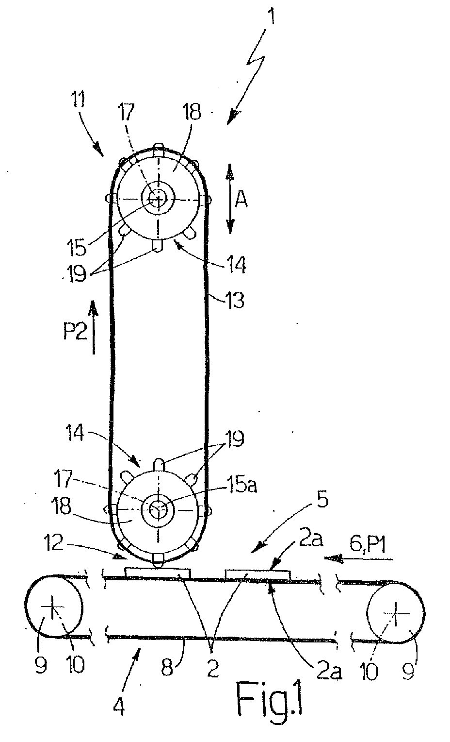
- each product 2 is substantially flat, is substantially rectangular parallelepiped-shaped, and is defined by two substantially parallel major lateral faces 2a.
- Unit 1 comprises an endless conveyor 4 for feeding a succession of groups 5 of products 2 in a given direction 6 and along a given path P1.
- Groups 5 are substantially equally spaced along conveyor 4, and each comprise a number of - in the example shown, three - products 2, which are aligned with one another in a direction 7 substantially crosswise to direction 6, and are fed along path P1 "laid flat", i.e. with relative faces 2a horizontal.
- Conveyor 4 comprises a belt 8 looped about two pulleys 9 - one of which is powered continuously - which are fitted to a fixed frame (not shown) of unit 1 to rotate, with respect to the frame (not shown), about respective axes 10 substantially parallel to each other and perpendicular to the Figure 1 plane.
- Unit 1 also comprises a decorating device 11 located along path P1 at a decorating station 12, and in turn comprising a flexible decorating member 13, which is moved by an actuating device 14 along an endless path P2, and is located over conveyor 4, at a given distance from products 2 for decorating.
- a decorating device 11 located along path P1 at a decorating station 12, and in turn comprising a flexible decorating member 13, which is moved by an actuating device 14 along an endless path P2, and is located over conveyor 4, at a given distance from products 2 for decorating.
- Device 14 comprises two shafts 15 - one of which (hereinafter indicated 15a) is located beneath the other and is powered continuously by an electric motor 16 - which are fitted to said frame (not shown) to rotate, with respect to the frame (not shown), about respective axes 17, which extend substantially parallel to each other and to axes 10, and are substantially aligned with each other in a vertical direction A perpendicular to directions 6 and 7.
- Each shaft 15 is fitted, at each free end, with a wheel 18 having a number of pins 19, which are equally spaced about relative axis 17, and extend radially outwards from the outer surface of wheel 18 to engage corresponding holes 20 formed along the lateral edges of member 13, and so rotate member 13 about axes 17 and along path P2.
- Member 13 comprises a number of groups 21 of patterns 3, which are arranged along member 13 with substantially the same spacing as groups 5, and each comprise a respective number of patterns 3 (equal to the number of products 2 in each group 5), each of which is defined by at least one hole 22 formed through member 13, and is advanced in time with a relative product 2.
- device 11 also comprises a hopper 23 for containing a decorating material (in the example shown, a powdered or granular decorating material), and which extends in direction 7, is located between the two vertical branches of member 13, and in turn comprises a downwardly-converging top portion 24, and a bottom portion 25 defined by a tubular body 26 extending about shaft 15a and coaxial with relative axis 17.
- a decorating material in the example shown, a powdered or granular decorating material
- Body 26 has a diameter substantially equal to the diameter of wheels 18, and comprises a top opening 27 formed radially through body 26 so as to face portion 24; and a number of bottom slots 28, which are equal in number to products 2 in each group 5, and therefore to patterns 3 in each group 21, are formed radially through body 26 so as to face member 13, and are each of a width, measured parallel to direction 7, at least equal to the width of a product 2, also measured parallel to direction 7.
- Hopper 23 also comprises a valve device 29 for selectively controlling supply of said decorating material through slots 28, and therefore through holes 22, and which comprises a shutter member 30 defined by a tubular body 31 extending through body 26 and about shaft 15a, and substantially coaxial with axis 17 of shaft 15a.
- Body 31 comprises a top opening 32 formed radially through body 31 and facing opening 27; and a number of bottom slots 33, which are equal in number to slots 28, are formed radially through body 31, and are each of a width, measured parallel to direction 7, at least equal to the width of a slot 28.
- Body 31 is fitted in rotary and axially fixed manner to both body 26 and shaft 15a, and is oscillated - with respect to body 26 and shaft 15a, and by an actuating device 34 - about relative axis 17 and between an open position opening slots 28 (Figure 3) and a closed position closing slots 28 ( Figure 4).
- Device 34 comprises two actuating cylinders 35, which are located on opposite sides of body 26 in direction 7 and inside the two vertical branches of member 13, are hinged to said frame (not shown) of unit 1, and have respective output rods 36, the free ends of which are hinged to respective levers 37 extending outwards from the outer surface of body 31.
- conveyor 4 and decorating member 13 are operated continuously to feed each product 2 through decorating station 12 in time with a relative pattern 3; and shutter member 30 is moved into the open position as patterns 3 travel past slots 28, to allow the decorating material to drop down on to products 2, and is moved into the closed position as the portions of member 13 with no patterns 3 travel past slots 28.
- unit 1 As such, unit 1:
Landscapes
- Engineering & Computer Science (AREA)
- Mechanical Engineering (AREA)
- Structural Engineering (AREA)
- Chemical & Material Sciences (AREA)
- Ceramic Engineering (AREA)
- Devices For Post-Treatments, Processing, Supply, Discharge, And Other Processes (AREA)
- Adornments (AREA)
- Preparation Of Clay, And Manufacture Of Mixtures Containing Clay Or Cement (AREA)
- Laminated Bodies (AREA)
Abstract
Description
Claims (7)
- A unit for decorating ceramic products (2) with relative patterns (3); the unit comprising a decorating device (11) for successively decorating groups (5) of products (2), each comprising at least one respective product (2); the decorating device (11) comprising at least one decorating member (13) having a number of holes (22), each said pattern (3) being defined by at least one said hole (22), and feed means (23) for feeding a decorating material through said holes (22); and the unit being characterized in that said decorating member (13) is a flexible member extending along an endless path (P2); first actuating means (4) moving the decorating member (13) and the group (5) for decorating with respect to each other in a given first direction (6); and second actuating means (14) moving the decorating member (13) along said path (P2).
- A unit as claimed in Claim 1, and also comprising a decorating station (12) at which said decorating member (13) is located; said first actuating means (4) comprising a conveyor (4) for feeding said groups (5) continuously through said decorating station (12); and said second actuating means (14) moving said decorating member (13) continuously along said path (P2).
- A unit as claimed in Claim 1 or 2, wherein said first and second actuating means (4, 14) are timed with respect to each other so as to advance each said group (5) in time with the relative said patterns (3).
- A unit as claimed in any one of the foregoing Claims, wherein said second actuating means (14) comprise two supporting shafts (15) for supporting said decorating member (13); said supporting shafts (15) being mounted for rotation about respective longitudinal axes (17) substantially aligned with each other in a second direction (A) substantially crosswise to said first direction (6).
- A unit as claimed in Claim 4, wherein said second direction (A) is a substantially vertical direction.
- A unit as claimed in Claim 4 or 5, wherein said feed means (23) comprise a hopper (23) having a bottom portion (25) extending about one of said supporting shafts (15) and having, for each product (2) in each group (5) of products (2), an outlet (28) facing said decorating member (13), and valve means (29) movable between an open position and a closed position respectively opening and closing said outlets (28).
- A unit as claimed in Claim 6, wherein said bottom portion (25) is substantially cylindrical; said valve means (29) comprising at least one shutter member (30) substantially concentric with said outlets (28) and movable between said open position and said closed position.
Applications Claiming Priority (2)
| Application Number | Priority Date | Filing Date | Title |
|---|---|---|---|
| IT2001BO000340A ITBO20010340A1 (en) | 2001-05-29 | 2001-05-29 | UNIT FOR THE DECORATION OF CERAMIC PRODUCTS |
| ITBO20010340 | 2001-05-29 |
Publications (3)
| Publication Number | Publication Date |
|---|---|
| EP1266757A2 true EP1266757A2 (en) | 2002-12-18 |
| EP1266757A3 EP1266757A3 (en) | 2003-02-19 |
| EP1266757B1 EP1266757B1 (en) | 2007-12-19 |
Family
ID=11439385
Family Applications (1)
| Application Number | Title | Priority Date | Filing Date |
|---|---|---|---|
| EP02011877A Expired - Lifetime EP1266757B1 (en) | 2001-05-29 | 2002-05-28 | Unit for decorating ceramic products |
Country Status (4)
| Country | Link |
|---|---|
| EP (1) | EP1266757B1 (en) |
| DE (1) | DE60224134T2 (en) |
| ES (1) | ES2298308T3 (en) |
| IT (1) | ITBO20010340A1 (en) |
Cited By (3)
| Publication number | Priority date | Publication date | Assignee | Title |
|---|---|---|---|---|
| EP1598502A3 (en) * | 2004-01-08 | 2007-05-30 | D'Hondt, Albert | Tile coating apparatus for flooring |
| WO2009044319A3 (en) * | 2007-10-03 | 2009-07-23 | Antonio Maccari | Controlling the funtioning of decorating machines |
| US8337947B2 (en) | 2006-02-21 | 2012-12-25 | System S.P.A. | Decorating with powder material |
Families Citing this family (1)
| Publication number | Priority date | Publication date | Assignee | Title |
|---|---|---|---|---|
| CN108943348B (en) * | 2018-08-20 | 2024-06-04 | 佛山市赛普飞特科技有限公司 | Digital printing equipment using ceramic powder |
Family Cites Families (2)
| Publication number | Priority date | Publication date | Assignee | Title |
|---|---|---|---|---|
| EP1040920A1 (en) * | 1999-03-17 | 2000-10-04 | Gomes Technology S.p.A. | A silk-screen decorating machine |
| EP1157832A1 (en) * | 2000-05-15 | 2001-11-28 | Tecno-Italia S.R.L. | Impression device for silk-screen printing machines |
-
2001
- 2001-05-29 IT IT2001BO000340A patent/ITBO20010340A1/en unknown
-
2002
- 2002-05-28 ES ES02011877T patent/ES2298308T3/en not_active Expired - Lifetime
- 2002-05-28 DE DE60224134T patent/DE60224134T2/en not_active Expired - Fee Related
- 2002-05-28 EP EP02011877A patent/EP1266757B1/en not_active Expired - Lifetime
Cited By (4)
| Publication number | Priority date | Publication date | Assignee | Title |
|---|---|---|---|---|
| EP1598502A3 (en) * | 2004-01-08 | 2007-05-30 | D'Hondt, Albert | Tile coating apparatus for flooring |
| US8337947B2 (en) | 2006-02-21 | 2012-12-25 | System S.P.A. | Decorating with powder material |
| EP2687347A2 (en) | 2006-02-21 | 2014-01-22 | System Spa | Decorating with powder material. |
| WO2009044319A3 (en) * | 2007-10-03 | 2009-07-23 | Antonio Maccari | Controlling the funtioning of decorating machines |
Also Published As
| Publication number | Publication date |
|---|---|
| ES2298308T3 (en) | 2008-05-16 |
| DE60224134D1 (en) | 2008-01-31 |
| ITBO20010340A0 (en) | 2001-05-29 |
| DE60224134T2 (en) | 2008-12-04 |
| EP1266757A3 (en) | 2003-02-19 |
| ITBO20010340A1 (en) | 2002-11-29 |
| EP1266757B1 (en) | 2007-12-19 |
Similar Documents
| Publication | Publication Date | Title |
|---|---|---|
| JP6517825B2 (en) | Transport assembly for a transport system | |
| US4189996A (en) | Conveyor link and capsule guide for printers | |
| US4135619A (en) | Apparatus for transferring confectionery products from a feeding conveyor to a receiving conveyor | |
| EP0885821B1 (en) | Apparatus for aligning products having an approximately rectangular cross-section | |
| US20060250464A1 (en) | Method and apparatus for printing selected information on bottles | |
| US4657130A (en) | Discrete solid object feeding and transport apparatus and method | |
| EP0962390B1 (en) | Unit and method for forming a group of products on a wrapping machine | |
| EP3059173B1 (en) | Device for producing packages | |
| CA2272827A1 (en) | Conveyor apparatus for depositing products in groups into containers | |
| KR890017075A (en) | Second Stage Tire Maker and Method | |
| EP1266757B1 (en) | Unit for decorating ceramic products | |
| EP1442984B1 (en) | Packaging machine for wrapping products in respective sheets of heat-seal wrapping material | |
| US6470651B1 (en) | Method and device for feeding groups of cigarettes to a continuous wrapping line of a packing machine | |
| EP1440679A1 (en) | Unit for feeding capsules onto a capsule filling machine | |
| US6453784B1 (en) | Apparatus for cutting individual pieces from a continuously moving extruded strand | |
| DE60026211T3 (en) | Automatic machine with a cordless controlled operating wheel | |
| ITBO970221A1 (en) | CIGARETTE PACKING MACHINE WITH MULTIPLE WRAPPING LINES. | |
| EP1204553B1 (en) | Device for metering a group of articles | |
| US5501443A (en) | Device for the release of folded products | |
| CN119460420B (en) | Multiple anti-fake wrapping bag and lithography apparatus thereof | |
| US7305804B2 (en) | Outlet device for chocolates and the like | |
| US1891307A (en) | Feeding device | |
| KR200243416Y1 (en) | Apparatus for printing on gunny bag in gunny bag producing machine | |
| KR950007089Y1 (en) | Direction change transfer device of medicine package | |
| KR20140065139A (en) | Apparatus and method for forming cubic design of textile |
Legal Events
| Date | Code | Title | Description |
|---|---|---|---|
| PUAI | Public reference made under article 153(3) epc to a published international application that has entered the european phase |
Free format text: ORIGINAL CODE: 0009012 |
|
| AK | Designated contracting states |
Kind code of ref document: A2 Designated state(s): AT BE CH CY DE DK ES FI FR GB GR IE IT LI LU MC NL PT SE TR |
|
| AX | Request for extension of the european patent |
Free format text: AL;LT;LV;MK;RO;SI |
|
| PUAL | Search report despatched |
Free format text: ORIGINAL CODE: 0009013 |
|
| AK | Designated contracting states |
Designated state(s): AT BE CH CY DE DK ES FI FR GB GR IE IT LI LU MC NL PT SE TR |
|
| AX | Request for extension of the european patent |
Extension state: AL LT LV MK RO SI |
|
| RIC1 | Information provided on ipc code assigned before grant |
Ipc: 7B 41F 15/08 B Ipc: 7B 41F 17/00 A |
|
| 17P | Request for examination filed |
Effective date: 20030814 |
|
| AKX | Designation fees paid |
Designated state(s): DE ES IT |
|
| GRAP | Despatch of communication of intention to grant a patent |
Free format text: ORIGINAL CODE: EPIDOSNIGR1 |
|
| GRAS | Grant fee paid |
Free format text: ORIGINAL CODE: EPIDOSNIGR3 |
|
| GRAA | (expected) grant |
Free format text: ORIGINAL CODE: 0009210 |
|
| AK | Designated contracting states |
Kind code of ref document: B1 Designated state(s): DE ES IT |
|
| REF | Corresponds to: |
Ref document number: 60224134 Country of ref document: DE Date of ref document: 20080131 Kind code of ref document: P |
|
| REG | Reference to a national code |
Ref country code: ES Ref legal event code: FG2A Ref document number: 2298308 Country of ref document: ES Kind code of ref document: T3 |
|
| PGFP | Annual fee paid to national office [announced via postgrant information from national office to epo] |
Ref country code: ES Payment date: 20080424 Year of fee payment: 7 Ref country code: DE Payment date: 20080516 Year of fee payment: 7 |
|
| PGFP | Annual fee paid to national office [announced via postgrant information from national office to epo] |
Ref country code: IT Payment date: 20080522 Year of fee payment: 7 |
|
| PLBE | No opposition filed within time limit |
Free format text: ORIGINAL CODE: 0009261 |
|
| STAA | Information on the status of an ep patent application or granted ep patent |
Free format text: STATUS: NO OPPOSITION FILED WITHIN TIME LIMIT |
|
| 26N | No opposition filed |
Effective date: 20080922 |
|
| PG25 | Lapsed in a contracting state [announced via postgrant information from national office to epo] |
Ref country code: DE Free format text: LAPSE BECAUSE OF NON-PAYMENT OF DUE FEES Effective date: 20091201 |
|
| REG | Reference to a national code |
Ref country code: ES Ref legal event code: FD2A Effective date: 20090529 |
|
| PG25 | Lapsed in a contracting state [announced via postgrant information from national office to epo] |
Ref country code: ES Free format text: LAPSE BECAUSE OF NON-PAYMENT OF DUE FEES Effective date: 20090529 |
|
| PG25 | Lapsed in a contracting state [announced via postgrant information from national office to epo] |
Ref country code: IT Free format text: LAPSE BECAUSE OF NON-PAYMENT OF DUE FEES Effective date: 20090528 |