EP1267001A1 - Compactor with vibrating bottom plate - Google Patents
Compactor with vibrating bottom plate Download PDFInfo
- Publication number
- EP1267001A1 EP1267001A1 EP01850105A EP01850105A EP1267001A1 EP 1267001 A1 EP1267001 A1 EP 1267001A1 EP 01850105 A EP01850105 A EP 01850105A EP 01850105 A EP01850105 A EP 01850105A EP 1267001 A1 EP1267001 A1 EP 1267001A1
- Authority
- EP
- European Patent Office
- Prior art keywords
- bottom plate
- machine
- vibrating element
- accumulator unit
- electric motor
- Prior art date
- Legal status (The legal status is an assumption and is not a legal conclusion. Google has not performed a legal analysis and makes no representation as to the accuracy of the status listed.)
- Granted
Links
- 239000004576 sand Substances 0.000 claims abstract description 5
- 238000005303 weighing Methods 0.000 claims abstract description 3
- 239000006096 absorbing agent Substances 0.000 claims description 6
- 230000033001 locomotion Effects 0.000 claims description 4
- 239000002184 metal Substances 0.000 description 13
- 229910052751 metal Inorganic materials 0.000 description 13
- 238000002485 combustion reaction Methods 0.000 description 7
- 230000005540 biological transmission Effects 0.000 description 5
- 238000001816 cooling Methods 0.000 description 4
- 229920001971 elastomer Polymers 0.000 description 3
- 239000007789 gas Substances 0.000 description 3
- 230000000266 injurious effect Effects 0.000 description 2
- 239000012212 insulator Substances 0.000 description 2
- 238000002360 preparation method Methods 0.000 description 2
- 230000000644 propagated effect Effects 0.000 description 2
- 229910001018 Cast iron Inorganic materials 0.000 description 1
- 230000001419 dependent effect Effects 0.000 description 1
- 229920001821 foam rubber Polymers 0.000 description 1
- 239000000446 fuel Substances 0.000 description 1
- 238000012423 maintenance Methods 0.000 description 1
- 238000004519 manufacturing process Methods 0.000 description 1
- 239000000463 material Substances 0.000 description 1
- 239000002689 soil Substances 0.000 description 1
Images


Classifications
-
- E—FIXED CONSTRUCTIONS
- E01—CONSTRUCTION OF ROADS, RAILWAYS, OR BRIDGES
- E01C—CONSTRUCTION OF, OR SURFACES FOR, ROADS, SPORTS GROUNDS, OR THE LIKE; MACHINES OR AUXILIARY TOOLS FOR CONSTRUCTION OR REPAIR
- E01C19/00—Machines, tools or auxiliary devices for preparing or distributing paving materials, for working the placed materials, or for forming, consolidating, or finishing the paving
- E01C19/22—Machines, tools or auxiliary devices for preparing or distributing paving materials, for working the placed materials, or for forming, consolidating, or finishing the paving for consolidating or finishing laid-down unset materials
- E01C19/30—Tamping or vibrating apparatus other than rollers ; Devices for ramming individual paving elements
- E01C19/34—Power-driven rammers or tampers, e.g. air-hammer impacted shoes for ramming stone-sett paving; Hand-actuated ramming or tamping machines, e.g. tampers with manually hoisted dropping weight
- E01C19/38—Power-driven rammers or tampers, e.g. air-hammer impacted shoes for ramming stone-sett paving; Hand-actuated ramming or tamping machines, e.g. tampers with manually hoisted dropping weight with means specifically for generating vibrations, e.g. vibrating plate compactors, immersion vibrators
-
- E—FIXED CONSTRUCTIONS
- E02—HYDRAULIC ENGINEERING; FOUNDATIONS; SOIL SHIFTING
- E02D—FOUNDATIONS; EXCAVATIONS; EMBANKMENTS; UNDERGROUND OR UNDERWATER STRUCTURES
- E02D3/00—Improving or preserving soil or rock, e.g. preserving permafrost soil
- E02D3/02—Improving by compacting
- E02D3/046—Improving by compacting by tamping or vibrating, e.g. with auxiliary watering of the soil
- E02D3/074—Vibrating apparatus operating with systems involving rotary unbalanced masses
Definitions
- the present invention relates to a compactor, comprising a bottom plate which for compacting of sand, gravel, macadam etc. is vibratable by means of a vibrating element which is rigidly connected to the bottom plate, and an upper part which is elastically connected to the bottom plate and adapted to weigh down the bottom plate and which supports a drive motor for driving the vibrating element.
- Machines of the type mentioned by way of introduction have been known for a long time and are used when working with the soil, such as in connection with paving, road building, asphalting or preparation of foundations and ditches. They have a petrol- or diesel-powered internal combustion engine, which hydraulically or by means of a drive belt drives a rotary shaft of a vibrating element, on which shaft weights are eccentrically arranged to cause the vibrating element to vibrate at a frequency which is dependent on the speed of rotation of the rotary shaft.
- a drawback of the prior art machines is that their internal combustion engines produce exhaust gases which influence the environment as such and in particular the operator's work environment, especially when working in deep ditches in which the exhaust gases often remain for a long time.
- a further drawback is that the internal combustion engines also cause undesirable vibrations which via the operating handle of the machine are propagated to the operator and thus can injure him. Since the engine as well as the operating handle are mounted on the upper part of the machine, it is more difficult to keep these vibrations away from the operating handle than the vibrating motions from the bottom plate which in fact is elastically connected to the upper part of the machine.
- One more drawback is that the prior art petrol-powered and, in particular the diesel-powered, engines of the machines cause heavy noise, which means that also driving on fine-grained materials, such as sand, which only cause a relatively faint sound, is accompanied by noise on acoustic pressure levels that are injurious to health.
- the object of the invention is to provide a compactor of the type mentioned by way of introduction, which can operate freely and independently, does not cause any exhaust gases injurious to health, is easy to devibrate and has a motor which operates more silently than a petrol or diesel engine.
- the drive motor is an electric motor, which is driven by an electric accumulator unit which is mounted on the upper part and which comprises at least one rechargeable battery which constitutes a weight for weighing down the bottom plate.
- the weight of the rechargeable battery to load or weigh down the bottom plate and, of course, by simultaneously minimising the weight of the upper part, will it be possible to provide a battery-operated compactor, whose total weight with regard to its power can be compared with that of a traditional machine with an internal combustion engine, with a battery capacity which suffices for about 1.5-2 hours of operation, which well satisfies the need during a normal work day for such a machine, for instance in connection with paving or preparation of ditches.
- the fact that the limit for the total weight is not exceeded, as well as a low point of balance, is important for the operability of a compactor, i.e. a traditional machine, originally intended for an internal combustion engine but provided with an electric motor and an associated battery, would be too heavy and unstable for practical use.
- the vibrating element is preferably arranged at the front edge of the bottom plate seen in the travelling direction of the machine, and the electric motor is arranged behind and essentially on the same level as said element.
- the electric motor is arranged behind and essentially on the same level as said element.
- the electric motor is adapted to drive the vibrating element by means of a drive belt since this is the type of transmission that has the lowest weight and which consequently provides space for a maximum of battery capacity.
- the vibrating element and the electric motor can form a unit, which with respect to the travelling direction of the machine is arranged at the front edge or centre of the bottom plate.
- the upper part has impact absorbers which are directed towards the bottom plate and adapted to softly absorb great motions of the upper part which are directed towards the bottom plate. This is very important for the compactor according to the invention since otherwise there is a risk that the battery will be damaged, for instance when unloading the machine from a lorry platform in a careless manner.
- the accumulator unit suitably comprises a charger which is directly connectable to mains for charging the rechargeable battery since in this way it will be easy to ensure that the battery of the machine is properly charged when necessary.
- the accumulator unit is a module which in one piece is mountable on and removable from the upper part.
- a solution involving a module is practical since it easily enables manufacture of machines with different battery capacities and/or with chargers of different capacities and since it facilitates maintenance.
- the accumulator unit preferably comprises at least two rechargeable batteries and a yoke which extends over the batteries to retain them on the accumulator unit and which has a first end pivotally connected to the accumulator unit and a second end releasably connected to the accumulator unit, in such manner that the yoke, when its second end is released, is pivotable away for simultaneous release of the batteries.
- the prior art compactor 1 shown in Figs 1 and 2 has a bottom plate 2, which for compacting of sand, gravel, macadam etc. is vibratable by means of a vibrating element 3 of the above-mentioned type, which, seen in the travelling direction F of the machine 1 at the front edge of the bottom plate 2, is rigidly connected to this plate 2.
- the machine 1 has an upper part 4 which is elastically connected to the bottom plate 2 by means of vibration insulators (not shown), is adapted to weigh down the bottom plate 2 and supports an internal combustion engine 5 for driving the vibrating element 3.
- the transmission between the engine 5 and the vibrating element 3 comprises a centrifugal clutch 6 on the output shaft of the engine and a drive belt 7 which runs over a pulley on the output shaft of the clutch 6 and over a pulley 8 on the shaft of the vibrating element.
- the machine 1 has an operating handle 9 fixed to the rear edge of the upper part 4 and, suspended from the operating handle, transport wheels 10 which, for moving the machine 1 in switched-off state, are attachable to the bottom plate 2 in a manner not shown.
- the embodiment of the compactor 11 according to the invention as illustrated in Figs 3-6 also has a bottom plate 12 which is vibratable by means of a vibrating element 13 arranged at the front edge of the bottom plate 12 and which by means of four rubber pads 14 is elastically connected to an upper part 15, which is adapted to weigh down the bottom plate 12.
- the upper part 15, supports an electric motor 16, which, seen in the travelling direction F of the machine, is arranged behind and essentially on the same level as the vibrating element 13 in a special, upwards open compartment 17 in a first sheet metal frame 18 associated with the upper part 15.
- the transmission between the motor 16 and the vibrating element 13 also in this case comprises a drive belt 19 which runs over pulleys 20, 21, but since the electric motor 16 need not be capable of idling, the centrifugal clutch of the prior art machine is missing and the driving pulley 21 is arranged on the shaft of the electric motor 16 instead.
- the machine 11 according to the invention also has an operating handle which is attached to the rear edge of the upper part 15.
- the handle is not shown in the drawings of the machine 11 since it may be designed in many different, but well-known, manners.
- the fixing points 22 of the handle on the first sheet metal frame 18 of the upper part 15 are consciously positioned at a low level in order to obtain as low a tilting moment as possible when operating the machine 11 sideways.
- three rechargeable lead batteries 23-25 along with a charger 26 are mounted in such manner on a second sheet metal frame 27 associated with the upper part 15 that they, together with this sheet metal frame 27 and a locking yoke 28 mounted on the sheet metal frame 27 which holds the batteries 23-25 in place, form a module 29 which is clearly illustrated in Fig. 6.
- the locking yoke 28 is designed and screwed to said second sheet metal frame 27 in such manner, that after removal of rear screws 30 on both sides of the second sheet metal frame 27, it can be pivoted forwards on front screws 31 on both sides of this sheet metal frame for simultaneous release of all three batteries 23, 25.
- the second sheet metal frame 27 has in its lower part lugs 32, 33 extending sideways, through which screws 34 can be inserted for attaching the second sheet metal frame 27 and, thus, the module 29 to the first sheet metal frame 18 of the upper part 15.
- impact absorbers of rubber are arranged between the upper part 15 and the bottom plate 12, on the one hand in the front part at 34 on the underside of the upper part 15 and, on the other hand, in the rear part at 35, which impact absorbers 34, 35, for operation, only come into contact with the respective opposite machine parts (the vibrating element 13 for the front impact absorbers 34 and the first sheet metal frame 18 for the rear impact absorbers 35) in connection with great motions of the upper part 15 towards the bottom plate 12.
- rubber pads 36, 37 are arranged between said locking yoke 28 and the batteries 23, 24, and the batteries 23, 25 can rest on a yieldable base of e.g. foam rubber (not shown) .
- the shown charger 26 has a very great capacity and can, by being connected to mains, recharge the batteries completely within a few hours. Owing to its great capacity, the charger has a relatively great cooling requirement which is satisfied by means of cooling flanges 38 which cover one side of the charger 26. This side is in the shown embodiment of the compactor 11 directed to the rear of the machine so that its cooling flanges 38 for maximum cooling extend essentially vertically and preferably are uncovered in a special vent opening in a machine cover (not shown) which covers and protects at least said module 29.
- the vibrating element instead of the illustrated simple variant may have a forward-back function
- the transmission instead of the shown drive belt solution may comprise hydraulic transmission
- the batteries instead of the shown lead batteries may be some other convenient type
- the charger instead of the shown quick charger may have a lower capacity for recharging of the batteries by night.
Landscapes
- Engineering & Computer Science (AREA)
- Structural Engineering (AREA)
- Civil Engineering (AREA)
- Life Sciences & Earth Sciences (AREA)
- Environmental & Geological Engineering (AREA)
- Soil Sciences (AREA)
- General Life Sciences & Earth Sciences (AREA)
- Mining & Mineral Resources (AREA)
- Paleontology (AREA)
- Agronomy & Crop Science (AREA)
- General Engineering & Computer Science (AREA)
- Architecture (AREA)
- Road Paving Machines (AREA)
Abstract
Description
- The present invention relates to a compactor, comprising a bottom plate which for compacting of sand, gravel, macadam etc. is vibratable by means of a vibrating element which is rigidly connected to the bottom plate, and an upper part which is elastically connected to the bottom plate and adapted to weigh down the bottom plate and which supports a drive motor for driving the vibrating element.
- Machines of the type mentioned by way of introduction have been known for a long time and are used when working with the soil, such as in connection with paving, road building, asphalting or preparation of foundations and ditches. They have a petrol- or diesel-powered internal combustion engine, which hydraulically or by means of a drive belt drives a rotary shaft of a vibrating element, on which shaft weights are eccentrically arranged to cause the vibrating element to vibrate at a frequency which is dependent on the speed of rotation of the rotary shaft.
- For the thus achieved vibrations, which owing to the rigid connection between the vibrating element and the bottom plate are propagated to the bottom plate, to cause as good compacting as possible, it is crucial for the vibrating bottom plate to be weighed down against the ground. This is traditionally achieved by the upper part of the machine being made of very thick metal sheet or cast iron.
- A great advantage of the prior art machines with their internal combustion engines is that after being filled with fuel they can operate freely and independently for relatively long periods.
- A drawback of the prior art machines is that their internal combustion engines produce exhaust gases which influence the environment as such and in particular the operator's work environment, especially when working in deep ditches in which the exhaust gases often remain for a long time.
- A further drawback is that the internal combustion engines also cause undesirable vibrations which via the operating handle of the machine are propagated to the operator and thus can injure him. Since the engine as well as the operating handle are mounted on the upper part of the machine, it is more difficult to keep these vibrations away from the operating handle than the vibrating motions from the bottom plate which in fact is elastically connected to the upper part of the machine.
- One more drawback is that the prior art petrol-powered and, in particular the diesel-powered, engines of the machines cause heavy noise, which means that also driving on fine-grained materials, such as sand, which only cause a relatively faint sound, is accompanied by noise on acoustic pressure levels that are injurious to health.
- In view of that stated above, the object of the invention is to provide a compactor of the type mentioned by way of introduction, which can operate freely and independently, does not cause any exhaust gases injurious to health, is easy to devibrate and has a motor which operates more silently than a petrol or diesel engine.
- According to the invention, this object is achieved in that the drive motor is an electric motor, which is driven by an electric accumulator unit which is mounted on the upper part and which comprises at least one rechargeable battery which constitutes a weight for weighing down the bottom plate.
- Only by consciously using according to the invention the weight of the rechargeable battery to load or weigh down the bottom plate and, of course, by simultaneously minimising the weight of the upper part, will it be possible to provide a battery-operated compactor, whose total weight with regard to its power can be compared with that of a traditional machine with an internal combustion engine, with a battery capacity which suffices for about 1.5-2 hours of operation, which well satisfies the need during a normal work day for such a machine, for instance in connection with paving or preparation of ditches. The fact that the limit for the total weight is not exceeded, as well as a low point of balance, is important for the operability of a compactor, i.e. a traditional machine, originally intended for an internal combustion engine but provided with an electric motor and an associated battery, would be too heavy and unstable for practical use.
- According to the invention, the vibrating element is preferably arranged at the front edge of the bottom plate seen in the travelling direction of the machine, and the electric motor is arranged behind and essentially on the same level as said element. Such an arrangement especially of the electric motor brings the advantage that the machine can be made very compact and low, which is advantageous for its operability.
- Preferably, the electric motor is adapted to drive the vibrating element by means of a drive belt since this is the type of transmission that has the lowest weight and which consequently provides space for a maximum of battery capacity.
- Alternatively, the vibrating element and the electric motor can form a unit, which with respect to the travelling direction of the machine is arranged at the front edge or centre of the bottom plate. The advantage of such a solution is that it is both relatively light-weight and compact and that it thus provides space for an accumulator unit with a very great capacity.
- Conveniently, the upper part has impact absorbers which are directed towards the bottom plate and adapted to softly absorb great motions of the upper part which are directed towards the bottom plate. This is very important for the compactor according to the invention since otherwise there is a risk that the battery will be damaged, for instance when unloading the machine from a lorry platform in a careless manner.
- The accumulator unit suitably comprises a charger which is directly connectable to mains for charging the rechargeable battery since in this way it will be easy to ensure that the battery of the machine is properly charged when necessary.
- Preferably, the accumulator unit is a module which in one piece is mountable on and removable from the upper part. Such a solution involving a module is practical since it easily enables manufacture of machines with different battery capacities and/or with chargers of different capacities and since it facilitates maintenance.
- Finally, the accumulator unit preferably comprises at least two rechargeable batteries and a yoke which extends over the batteries to retain them on the accumulator unit and which has a first end pivotally connected to the accumulator unit and a second end releasably connected to the accumulator unit, in such manner that the yoke, when its second end is released, is pivotable away for simultaneous release of the batteries. The advantage of this solution is that mounting and dismounting of the batteries is facilitated significantly and that incorrect mounting, which in the very demanding environment that is involved can easily cause damage to the batteries, is practically out of the question.
- A prior art compactor and a preferred embodiment of the inventive compactor will be described in more detail below with reference to the accompanying drawings, in which
- Fig. 1 is a side view of the prior art compactor;
- Fig. 2 is a front view of the prior art compactor, however with a portion of a belt cover broken away;
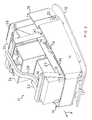
- Fig. 3 shows the most important parts of the machine according to the invention in perspective obliquely from the front;
- Fig. 4 is a corresponding perspective view of the bottom plate of this machine and also some associated parts;
- Fig. 5 is a corresponding perspective view of the drive motor of this machine and also some associated parts, however with a wall portion broken away; and
- Fig. 6 is a corresponding perspective view of the accumulator package of this machine.
-
- The
prior art compactor 1 shown in Figs 1 and 2 has abottom plate 2, which for compacting of sand, gravel, macadam etc. is vibratable by means of a vibrating element 3 of the above-mentioned type, which, seen in the travelling direction F of themachine 1 at the front edge of thebottom plate 2, is rigidly connected to thisplate 2. Moreover, themachine 1 has an upper part 4 which is elastically connected to thebottom plate 2 by means of vibration insulators (not shown), is adapted to weigh down thebottom plate 2 and supports aninternal combustion engine 5 for driving the vibrating element 3. The transmission between theengine 5 and the vibrating element 3 comprises a centrifugal clutch 6 on the output shaft of the engine and a drive belt 7 which runs over a pulley on the output shaft of the clutch 6 and over apulley 8 on the shaft of the vibrating element. Finally, themachine 1 has an operating handle 9 fixed to the rear edge of the upper part 4 and, suspended from the operating handle,transport wheels 10 which, for moving themachine 1 in switched-off state, are attachable to thebottom plate 2 in a manner not shown. - The embodiment of the
compactor 11 according to the invention as illustrated in Figs 3-6 also has abottom plate 12 which is vibratable by means of a vibratingelement 13 arranged at the front edge of thebottom plate 12 and which by means of fourrubber pads 14 is elastically connected to anupper part 15, which is adapted to weigh down thebottom plate 12. In thismachine 11, theupper part 15, however, supports anelectric motor 16, which, seen in the travelling direction F of the machine, is arranged behind and essentially on the same level as the vibratingelement 13 in a special, upwardsopen compartment 17 in a firstsheet metal frame 18 associated with theupper part 15. The transmission between themotor 16 and the vibratingelement 13 also in this case comprises adrive belt 19 which runs overpulleys electric motor 16 need not be capable of idling, the centrifugal clutch of the prior art machine is missing and the drivingpulley 21 is arranged on the shaft of theelectric motor 16 instead. Of course, themachine 11 according to the invention also has an operating handle which is attached to the rear edge of theupper part 15. However, the handle is not shown in the drawings of themachine 11 since it may be designed in many different, but well-known, manners. On the other hand, it should be pointed out that thefixing points 22 of the handle on the firstsheet metal frame 18 of theupper part 15 are consciously positioned at a low level in order to obtain as low a tilting moment as possible when operating themachine 11 sideways. - The
electric motor 11, which is mounted on themachine 11 according to the preferred embodiment of the invention, is an enclosed direct-current motor. For driving of the motor, three rechargeable lead batteries 23-25 along with acharger 26 are mounted in such manner on a secondsheet metal frame 27 associated with theupper part 15 that they, together with thissheet metal frame 27 and alocking yoke 28 mounted on thesheet metal frame 27 which holds the batteries 23-25 in place, form amodule 29 which is clearly illustrated in Fig. 6. As will be seen, thelocking yoke 28 is designed and screwed to said secondsheet metal frame 27 in such manner, that after removal ofrear screws 30 on both sides of the secondsheet metal frame 27, it can be pivoted forwards onfront screws 31 on both sides of this sheet metal frame for simultaneous release of all threebatteries sheet metal frame 27 has in itslower part lugs screws 34 can be inserted for attaching the secondsheet metal frame 27 and, thus, themodule 29 to the firstsheet metal frame 18 of theupper part 15. - In order to ensure that neither the
vibration insulators 14 nor the batteries 23-25 are damaged in careless handling of themachine 11, for instance when loading and unloading the same or when changing batteries and in connection with service, impact absorbers of rubber are arranged between theupper part 15 and thebottom plate 12, on the one hand in the front part at 34 on the underside of theupper part 15 and, on the other hand, in the rear part at 35, which impact absorbers 34, 35, for operation, only come into contact with the respective opposite machine parts (the vibratingelement 13 for the front impact absorbers 34 and the firstsheet metal frame 18 for the rear impact absorbers 35) in connection with great motions of theupper part 15 towards thebottom plate 12. Moreover, especially for protecting the batteries,rubber pads locking yoke 28 and thebatteries batteries - The shown
charger 26 has a very great capacity and can, by being connected to mains, recharge the batteries completely within a few hours. Owing to its great capacity, the charger has a relatively great cooling requirement which is satisfied by means ofcooling flanges 38 which cover one side of thecharger 26. This side is in the shown embodiment of thecompactor 11 directed to the rear of the machine so that itscooling flanges 38 for maximum cooling extend essentially vertically and preferably are uncovered in a special vent opening in a machine cover (not shown) which covers and protects at least saidmodule 29. - It will be appreciated that the above described embodiment of the
compactor 11 according to the invention can be modified in various ways within the scope of the claims and that, for instance, the vibrating element instead of the illustrated simple variant may have a forward-back function, the transmission instead of the shown drive belt solution may comprise hydraulic transmission, the batteries instead of the shown lead batteries may be some other convenient type and the charger instead of the shown quick charger may have a lower capacity for recharging of the batteries by night.
Claims (9)
- A compactor, comprising a bottom plate (12) which for compacting of sand, gravel, macadam etc. is vibratable by means of a vibrating element (13) which is rigidly connected to the bottom plate (12), and an upper part (15) which is elastically connected to the bottom plate (12) and adapted to weigh down the bottom plate (12) and which supports a drive motor (16) for driving the vibrating element (13), characterised in that the drive motor (16) is an electric motor, which is driven by an electric accumulator unit which is mounted on the upper part (15) and which comprises at least one rechargeable battery (23-25) which constitutes a weight for weighing down the bottom plate (12).
- A machine as claimed in claim 1, characterised in that the vibrating element (13) is arranged at the front edge of the bottom plate (12) seen in the travelling direction (F) of the machine, and that the electric motor (16) is arranged behind and essentially on the same level as said element (13).
- A machine as claimed in claim 1 or 2, characterised in that the electric motor is adapted to drive the vibrating element (13) by means of a drive belt (19).
- A machine as claimed in claim 1, characterised in that the vibrating element (13) and the electric motor form a unit, which with respect to the travelling direction (F) of the machine is arranged at the front edge of the bottom plate (12).
- A machine as claimed in claim 1, characterised in that the vibrating element (13) and the electric motor form a unit which with respect to the travelling direction (F) of the machine is arranged in the centre of the bottom plate (12).
- A machine as claimed in any one of claims 1-5, characterised in that the upper part (15) has impact absorbers (34, 35) which are directed towards the bottom plate (12) and adapted to softly absorb great motions of the upper part (15) which are directed towards the bottom plate (12).
- A machine as claimed in any one of claims 1-6, characterised in that the accumulator unit comprises a charger (26) which is directly connectable to mains for charging the rechargeable battery (23-25).
- A machine as claimed in any one of claims 1-7, characterised in that the accumulator unit is a module (29) which in one piece is mountable on and removable from the upper part (15).
- A machine as claimed in any one of claims 1-8, characterised in that the accumulator unit comprises at least two rechargeable batteries (23-25) and a yoke (28) which extends over the batteries (23-25) to retain them on the accumulator unit and which has a first end (31) pivotally connected to the accumulator unit and a second end (30) releasably connected to the accumulator unit, in such manner that the yoke (28), when its second end is released, is pivotable away for simultaneous release of the batteries (23-25).
Priority Applications (2)
| Application Number | Priority Date | Filing Date | Title |
|---|---|---|---|
| DE60139985T DE60139985D1 (en) | 2001-06-14 | 2001-06-14 | Compressor with vibration plate |
| EP20010850105 EP1267001B1 (en) | 2001-06-14 | 2001-06-14 | Compactor with vibrating bottom plate |
Applications Claiming Priority (1)
| Application Number | Priority Date | Filing Date | Title |
|---|---|---|---|
| EP20010850105 EP1267001B1 (en) | 2001-06-14 | 2001-06-14 | Compactor with vibrating bottom plate |
Publications (2)
| Publication Number | Publication Date |
|---|---|
| EP1267001A1 true EP1267001A1 (en) | 2002-12-18 |
| EP1267001B1 EP1267001B1 (en) | 2009-09-23 |
Family
ID=8184875
Family Applications (1)
| Application Number | Title | Priority Date | Filing Date |
|---|---|---|---|
| EP20010850105 Expired - Lifetime EP1267001B1 (en) | 2001-06-14 | 2001-06-14 | Compactor with vibrating bottom plate |
Country Status (2)
| Country | Link |
|---|---|
| EP (1) | EP1267001B1 (en) |
| DE (1) | DE60139985D1 (en) |
Cited By (14)
| Publication number | Priority date | Publication date | Assignee | Title |
|---|---|---|---|---|
| WO2010081674A1 (en) * | 2009-01-13 | 2010-07-22 | Wacker Neuson Se | Soil-compacting device |
| WO2012084074A1 (en) * | 2010-12-22 | 2012-06-28 | Wacker Neuson Produktion GmbH & Co. KG | Soil compacting device having an air-cooled battery |
| DE102012000711A1 (en) * | 2012-01-16 | 2013-07-18 | Wacker Neuson Produktion GmbH & Co. KG | Working device with vibration-decoupled energy storage |
| JP2013181324A (en) * | 2012-03-01 | 2013-09-12 | Hitachi Construction Machinery Camino Co Ltd | Vibration plate |
| EP2540912A3 (en) * | 2011-06-28 | 2014-10-01 | BOMAG GmbH | Device for soil compaction, in particular manual, with electrical drive and method for operating such a device |
| US9284697B2 (en) | 2011-06-15 | 2016-03-15 | Wacker Neuson Produktion GmbH & Co. KG | Ground-compacting device |
| DE102017121177A1 (en) | 2017-09-13 | 2019-03-28 | Wacker Neuson Produktion GmbH & Co. KG | Soil compacting device |
| DE102019108923A1 (en) * | 2019-04-04 | 2020-10-08 | Ammann Schweiz Ag | Soil compacting device with emission-free operating mode |
| DE102019110041A1 (en) * | 2019-04-16 | 2020-10-22 | Wacker Neuson Produktion GmbH & Co. KG | Hand-operated implement with decoupled drawbar carrier |
| EP4012100A1 (en) * | 2020-12-14 | 2022-06-15 | Wacker Neuson Produktion GmbH & Co. KG | Soil compacting device for compacting an area of soil |
| US20240079701A1 (en) * | 2022-09-02 | 2024-03-07 | Chongqing Tuosi Electric Power Technology Co., Ltd. | Electrically-driven power unit of compact battery pack and working machine |
| JP2024520866A (en) * | 2021-06-14 | 2024-05-24 | ハスクバーナ・アーベー | Electric compactor with battery system redundancy |
| US12139876B2 (en) | 2019-12-09 | 2024-11-12 | Husqvarna Ab | Compaction machine with electric working assembly |
| DE102024127906A1 (en) * | 2024-09-26 | 2026-03-26 | Wacker Neuson Produktion GmbH & Co. KG | Vibration plate with one-piece protective cover |
Families Citing this family (13)
| Publication number | Priority date | Publication date | Assignee | Title |
|---|---|---|---|---|
| DE102011115008A1 (en) * | 2011-10-06 | 2013-04-11 | Wacker Neuson Produktion GmbH & Co. KG | Power tool with protective cover |
| AU2019332824B2 (en) | 2018-08-28 | 2022-07-28 | Milwaukee Electric Tool Corporation | Battery-powered stand-alone motor unit |
| WO2021092552A1 (en) | 2019-11-08 | 2021-05-14 | Milwaukee Electric Tool Corporation | Battery-powered stand-alone motor unit |
| US12418220B2 (en) | 2019-11-08 | 2025-09-16 | Milwaukee Electric Tool Corporation | Battery-powered stand-alone motor unit |
| WO2021133929A1 (en) | 2019-12-23 | 2021-07-01 | Milwaukee Electric Tool Corporation | Battery-powered stand-alone motor unit |
| EP4179150A4 (en) * | 2020-07-07 | 2024-09-04 | Milwaukee Electric Tool Corporation | PLATE COMPACTOR |
| US20220010506A1 (en) * | 2020-07-07 | 2022-01-13 | Milwaukee Electric Tool Corporation | Plate compactor |
| EP4179151A4 (en) * | 2020-07-07 | 2024-09-04 | Milwaukee Electric Tool Corporation | Plate compactor |
| WO2022035959A1 (en) * | 2020-08-11 | 2022-02-17 | Milwaukee Electric Tool Corporation | Vibrating screed |
| CN221545201U (en) | 2021-07-30 | 2024-08-16 | 米沃奇电动工具公司 | Plate compactor |
| DE102021126365A1 (en) * | 2021-10-12 | 2023-04-13 | Hamm Ag | tillage machine |
| US12564981B2 (en) | 2022-07-14 | 2026-03-03 | Milwaukee Electric Tool Corporation | Log splitter |
| EP4635046A1 (en) | 2022-12-13 | 2025-10-22 | Husqvarna AB | Construction equipment with improved battery handling |
Citations (2)
| Publication number | Priority date | Publication date | Assignee | Title |
|---|---|---|---|---|
| GB2289490A (en) * | 1994-05-20 | 1995-11-22 | Mawsley Machinery Ltd | Vibratory compaction apparatus |
| DE19953553A1 (en) * | 1999-11-08 | 2000-06-21 | Joachim Mozdzanowski | Ground compactor with variable amplitude has two fixed inertial masses coupled to a central adjustable inertial mass via a double epicyclic drive |
-
2001
- 2001-06-14 DE DE60139985T patent/DE60139985D1/en not_active Expired - Lifetime
- 2001-06-14 EP EP20010850105 patent/EP1267001B1/en not_active Expired - Lifetime
Patent Citations (2)
| Publication number | Priority date | Publication date | Assignee | Title |
|---|---|---|---|---|
| GB2289490A (en) * | 1994-05-20 | 1995-11-22 | Mawsley Machinery Ltd | Vibratory compaction apparatus |
| DE19953553A1 (en) * | 1999-11-08 | 2000-06-21 | Joachim Mozdzanowski | Ground compactor with variable amplitude has two fixed inertial masses coupled to a central adjustable inertial mass via a double epicyclic drive |
Cited By (24)
| Publication number | Priority date | Publication date | Assignee | Title |
|---|---|---|---|---|
| WO2010081674A1 (en) * | 2009-01-13 | 2010-07-22 | Wacker Neuson Se | Soil-compacting device |
| CN102084068A (en) * | 2009-01-13 | 2011-06-01 | 威克纽森欧洲公司 | Soil-compacting device |
| US8317426B2 (en) | 2009-01-13 | 2012-11-27 | Wacker Neuson Produktion GmbH & Co. KG | Soil compacting device |
| CN102084068B (en) * | 2009-01-13 | 2014-03-12 | 威克纽森产品有限两合公司 | soil compaction device |
| WO2012084074A1 (en) * | 2010-12-22 | 2012-06-28 | Wacker Neuson Produktion GmbH & Co. KG | Soil compacting device having an air-cooled battery |
| US8708599B2 (en) | 2010-12-22 | 2014-04-29 | Wacker Neuson Produktion GmbH & Co. KG | Soil compacting device having an air-cooled battery |
| EP2857587A1 (en) * | 2010-12-22 | 2015-04-08 | Wacker Neuson Produktion GmbH & Co. KG | Soil compacting device having an air-cooled battery |
| US9284697B2 (en) | 2011-06-15 | 2016-03-15 | Wacker Neuson Produktion GmbH & Co. KG | Ground-compacting device |
| EP2540912A3 (en) * | 2011-06-28 | 2014-10-01 | BOMAG GmbH | Device for soil compaction, in particular manual, with electrical drive and method for operating such a device |
| DE102012000711A1 (en) * | 2012-01-16 | 2013-07-18 | Wacker Neuson Produktion GmbH & Co. KG | Working device with vibration-decoupled energy storage |
| EP2804987A1 (en) | 2012-01-16 | 2014-11-26 | Wacker Neuson Produktion GmbH & Co. KG | Ground compacting implement |
| JP2013181324A (en) * | 2012-03-01 | 2013-09-12 | Hitachi Construction Machinery Camino Co Ltd | Vibration plate |
| DE102017121177A1 (en) | 2017-09-13 | 2019-03-28 | Wacker Neuson Produktion GmbH & Co. KG | Soil compacting device |
| US10344439B2 (en) | 2017-09-13 | 2019-07-09 | Wacker Neuson Produktion GmbH & Co. KG | Soil compacting device |
| DE102019108923A1 (en) * | 2019-04-04 | 2020-10-08 | Ammann Schweiz Ag | Soil compacting device with emission-free operating mode |
| DE102019108923B4 (en) * | 2019-04-04 | 2020-12-03 | Ammann Schweiz Ag | Soil compacting device with emission-free operating mode |
| DE102019110041A1 (en) * | 2019-04-16 | 2020-10-22 | Wacker Neuson Produktion GmbH & Co. KG | Hand-operated implement with decoupled drawbar carrier |
| US11306446B2 (en) | 2019-04-16 | 2022-04-19 | Wacker Neusen Produktion GmbH & Co. KG | Hand-held work tool with decoupled drawbar carrier |
| US12139876B2 (en) | 2019-12-09 | 2024-11-12 | Husqvarna Ab | Compaction machine with electric working assembly |
| EP4012100A1 (en) * | 2020-12-14 | 2022-06-15 | Wacker Neuson Produktion GmbH & Co. KG | Soil compacting device for compacting an area of soil |
| JP2024520866A (en) * | 2021-06-14 | 2024-05-24 | ハスクバーナ・アーベー | Electric compactor with battery system redundancy |
| US20240079701A1 (en) * | 2022-09-02 | 2024-03-07 | Chongqing Tuosi Electric Power Technology Co., Ltd. | Electrically-driven power unit of compact battery pack and working machine |
| DE102024127906A1 (en) * | 2024-09-26 | 2026-03-26 | Wacker Neuson Produktion GmbH & Co. KG | Vibration plate with one-piece protective cover |
| EP4717820A1 (en) * | 2024-09-26 | 2026-04-01 | Wacker Neuson Produktion GmbH & Co. KG | Vibrating plate with a one-piece protective cover |
Also Published As
| Publication number | Publication date |
|---|---|
| EP1267001B1 (en) | 2009-09-23 |
| DE60139985D1 (en) | 2009-11-05 |
Similar Documents
| Publication | Publication Date | Title |
|---|---|---|
| EP1267001B1 (en) | Compactor with vibrating bottom plate | |
| US6742619B2 (en) | Engine mounts, such as for a skid steer loader, having internally snubbed shocks and vibration isolators, and a method of making the engine mounts | |
| US11306446B2 (en) | Hand-held work tool with decoupled drawbar carrier | |
| US20130004237A1 (en) | Apparatus for soil compaction, especially hand-operated, comprising an electric drive, and a method for operating such an apparatus | |
| US20240279884A1 (en) | An electric compactor with battery system redundancy | |
| GB2455627A (en) | Electric compactor | |
| US20250163656A1 (en) | Plate compactor | |
| US4067244A (en) | Self-propelled vibratory plate | |
| US20260085477A1 (en) | Vibratory Plate with One-Piece Protective Cover | |
| SE516357C2 (en) | Soil compacting machine with vibrating base plate, has vibration part driven by battery powered electric motor supported in top part of machine | |
| CN211872962U (en) | Lithium electric plate compactor | |
| JP3635389B2 (en) | Diaphragm device | |
| US20240429781A1 (en) | Vibrating plate compactor for compacting earth, soil or substrate, and method for operating the same and system | |
| JPH0316886Y2 (en) | ||
| EP2147163A1 (en) | Jaw crusher for a mobile rubble crushing device | |
| KR20220157763A (en) | Electric tractor | |
| SE544979C2 (en) | An electric compactor with battery system redundancy | |
| CN216018730U (en) | Plant protection unmanned aerial vehicle vibrating device that dusts | |
| CN219547494U (en) | Compacting machine | |
| SE545182C2 (en) | An electric compactor with mutually separate battery compartments and batteries with system redundancy | |
| JP7228910B2 (en) | vibration compactor | |
| JP2555967Y2 (en) | Backpack power blower | |
| JP2001003310A (en) | Compaction machine | |
| JP2003328313A (en) | Rolling plate of plate compactor | |
| KR200157208Y1 (en) | Medium and large dump truck stacker vibrator device |
Legal Events
| Date | Code | Title | Description |
|---|---|---|---|
| PUAI | Public reference made under article 153(3) epc to a published international application that has entered the european phase |
Free format text: ORIGINAL CODE: 0009012 |
|
| AK | Designated contracting states |
Kind code of ref document: A1 Designated state(s): AT BE CH CY DE DK ES FI FR GB GR IE IT LI LU MC NL PT SE TR |
|
| AX | Request for extension of the european patent |
Free format text: AL;LT;LV;MK;RO;SI |
|
| 17P | Request for examination filed |
Effective date: 20030611 |
|
| AKX | Designation fees paid |
Designated state(s): DE ES FR GB IT |
|
| 17Q | First examination report despatched |
Effective date: 20061222 |
|
| GRAP | Despatch of communication of intention to grant a patent |
Free format text: ORIGINAL CODE: EPIDOSNIGR1 |
|
| GRAS | Grant fee paid |
Free format text: ORIGINAL CODE: EPIDOSNIGR3 |
|
| GRAA | (expected) grant |
Free format text: ORIGINAL CODE: 0009210 |
|
| AK | Designated contracting states |
Kind code of ref document: B1 Designated state(s): DE ES FR GB IT |
|
| REG | Reference to a national code |
Ref country code: GB Ref legal event code: FG4D |
|
| REF | Corresponds to: |
Ref document number: 60139985 Country of ref document: DE Date of ref document: 20091105 Kind code of ref document: P |
|
| PG25 | Lapsed in a contracting state [announced via postgrant information from national office to epo] |
Ref country code: ES Free format text: LAPSE BECAUSE OF FAILURE TO SUBMIT A TRANSLATION OF THE DESCRIPTION OR TO PAY THE FEE WITHIN THE PRESCRIBED TIME-LIMIT Effective date: 20100103 |
|
| PLBE | No opposition filed within time limit |
Free format text: ORIGINAL CODE: 0009261 |
|
| STAA | Information on the status of an ep patent application or granted ep patent |
Free format text: STATUS: NO OPPOSITION FILED WITHIN TIME LIMIT |
|
| 26N | No opposition filed |
Effective date: 20100624 |
|
| PG25 | Lapsed in a contracting state [announced via postgrant information from national office to epo] |
Ref country code: IT Free format text: LAPSE BECAUSE OF FAILURE TO SUBMIT A TRANSLATION OF THE DESCRIPTION OR TO PAY THE FEE WITHIN THE PRESCRIBED TIME-LIMIT Effective date: 20090923 |
|
| REG | Reference to a national code |
Ref country code: FR Ref legal event code: PLFP Year of fee payment: 16 |
|
| REG | Reference to a national code |
Ref country code: FR Ref legal event code: PLFP Year of fee payment: 17 |
|
| PGFP | Annual fee paid to national office [announced via postgrant information from national office to epo] |
Ref country code: DE Payment date: 20200601 Year of fee payment: 20 Ref country code: FR Payment date: 20200529 Year of fee payment: 20 |
|
| PGFP | Annual fee paid to national office [announced via postgrant information from national office to epo] |
Ref country code: GB Payment date: 20200529 Year of fee payment: 20 |
|
| REG | Reference to a national code |
Ref country code: DE Ref legal event code: R071 Ref document number: 60139985 Country of ref document: DE |
|
| REG | Reference to a national code |
Ref country code: GB Ref legal event code: PE20 Expiry date: 20210613 |
|
| PG25 | Lapsed in a contracting state [announced via postgrant information from national office to epo] |
Ref country code: GB Free format text: LAPSE BECAUSE OF EXPIRATION OF PROTECTION Effective date: 20210613 |