EP1267068A2 - Diesel fuel filter with water separation means - Google Patents
Diesel fuel filter with water separation means Download PDFInfo
- Publication number
- EP1267068A2 EP1267068A2 EP02012342A EP02012342A EP1267068A2 EP 1267068 A2 EP1267068 A2 EP 1267068A2 EP 02012342 A EP02012342 A EP 02012342A EP 02012342 A EP02012342 A EP 02012342A EP 1267068 A2 EP1267068 A2 EP 1267068A2
- Authority
- EP
- European Patent Office
- Prior art keywords
- sleeve
- filter
- basket
- cover
- side wall
- Prior art date
- Legal status (The legal status is an assumption and is not a legal conclusion. Google has not performed a legal analysis and makes no representation as to the accuracy of the status listed.)
- Withdrawn
Links
Images


Classifications
-
- B—PERFORMING OPERATIONS; TRANSPORTING
- B01—PHYSICAL OR CHEMICAL PROCESSES OR APPARATUS IN GENERAL
- B01D—SEPARATION
- B01D27/00—Cartridge filters of the throw-away type
- B01D27/14—Cartridge filters of the throw-away type having more than one filtering element
- B01D27/146—Cartridge filters of the throw-away type having more than one filtering element connected in series
- B01D27/148—Cartridge filters of the throw-away type having more than one filtering element connected in series arranged concentrically or coaxially
-
- B—PERFORMING OPERATIONS; TRANSPORTING
- B01—PHYSICAL OR CHEMICAL PROCESSES OR APPARATUS IN GENERAL
- B01D—SEPARATION
- B01D27/00—Cartridge filters of the throw-away type
- B01D27/04—Cartridge filters of the throw-away type with cartridges made of a piece of unitary material, e.g. filter paper
- B01D27/06—Cartridge filters of the throw-away type with cartridges made of a piece of unitary material, e.g. filter paper with corrugated, folded or wound material
- B01D27/07—Cartridge filters of the throw-away type with cartridges made of a piece of unitary material, e.g. filter paper with corrugated, folded or wound material having a coaxial stream through the filtering element
-
- B—PERFORMING OPERATIONS; TRANSPORTING
- B01—PHYSICAL OR CHEMICAL PROCESSES OR APPARATUS IN GENERAL
- B01D—SEPARATION
- B01D36/00—Filter circuits or combinations of filters with other separating devices
- B01D36/003—Filters in combination with devices for the removal of liquids
-
- F—MECHANICAL ENGINEERING; LIGHTING; HEATING; WEAPONS; BLASTING
- F02—COMBUSTION ENGINES; HOT-GAS OR COMBUSTION-PRODUCT ENGINE PLANTS
- F02M—SUPPLYING COMBUSTION ENGINES IN GENERAL WITH COMBUSTIBLE MIXTURES OR CONSTITUENTS THEREOF
- F02M37/00—Apparatus or systems for feeding liquid fuel from storage containers to carburettors or fuel-injection apparatus; Arrangements for purifying liquid fuel specially adapted for, or arranged on, internal-combustion engines
- F02M37/22—Arrangements for purifying liquid fuel specially adapted for, or arranged on, internal-combustion engines, e.g. arrangements in the feeding system
- F02M37/24—Arrangements for purifying liquid fuel specially adapted for, or arranged on, internal-combustion engines, e.g. arrangements in the feeding system characterised by water separating means
-
- F—MECHANICAL ENGINEERING; LIGHTING; HEATING; WEAPONS; BLASTING
- F02—COMBUSTION ENGINES; HOT-GAS OR COMBUSTION-PRODUCT ENGINE PLANTS
- F02M—SUPPLYING COMBUSTION ENGINES IN GENERAL WITH COMBUSTIBLE MIXTURES OR CONSTITUENTS THEREOF
- F02M37/00—Apparatus or systems for feeding liquid fuel from storage containers to carburettors or fuel-injection apparatus; Arrangements for purifying liquid fuel specially adapted for, or arranged on, internal-combustion engines
- F02M37/22—Arrangements for purifying liquid fuel specially adapted for, or arranged on, internal-combustion engines, e.g. arrangements in the feeding system
- F02M37/32—Arrangements for purifying liquid fuel specially adapted for, or arranged on, internal-combustion engines, e.g. arrangements in the feeding system characterised by filters or filter arrangements
- F02M37/34—Arrangements for purifying liquid fuel specially adapted for, or arranged on, internal-combustion engines, e.g. arrangements in the feeding system characterised by filters or filter arrangements by the filter structure, e.g. honeycomb, mesh or fibrous
Definitions
- the present invention relates to a Diesel fuel filter.
- filters are inserted on the circuit that feeds the fuel of Diesel engines, commonly known as Diesel fuel, and comprise a substantially cylindrical outer enclosure with a bottom and a cover and have a filtering mass in the form of rolled-up paper contained within a portion of space that is delimited by said outer enclosure at the side walls and by a sleeve that is coaxial to the enclosure and is in contact, in an upper region, with the cover and is spaced from the bottom in a lower region.
- Such portion of space for containing the filtering mass is open, in an upper region, onto a chamber that lies below the cover at the peripheral region of the sleeve, and is open, in a lower region, onto a water collection chamber proximate to the bottom of the enclosure, and therefore the filtering mass is designed to be crossed, in a direction that is substantially parallel to the axis of the filter, by the fuel, which enters the filter through connectors provided in the peripheral region of the cover, passes through the filtering mass, reaching the lower chamber, and then rises through the sleeve and exits at an output connector located at the center of the cover.
- the aim of the present invention is to provide a Diesel fuel filter of the described type that has means effective to separate the water contained in the fuel, which is not retained sufficiently by the described filtering mass and must not reach the motor because it could damage it.
- a Diesel fuel filter which comprises a substantially cylindrical outer enclosure that has a bottom and a cover and is provided with a filtering mass in the form of rolled-up paper contained within a portion of space that is delimited at the side walls by said outer enclosure and by a sleeve that is coaxial to the enclosure, is in contact in an upper region with the cover and in a lower region is spaced from the bottom, said sleeve being open in an upper region onto a chamber that lies below the cover at the peripheral region of the sleeve and being open, in a lower region, onto a water collection chamber, said filtering mass being arranged to as to be crossed by the fuel that enters the filter through connectors provided in the peripheral region of the cover, passes through the mass with a direction that is substantially parallel to the axis of the filter, reaching the lower chamber, rises through the sleeve and exits from the filter through an output connector provided at the center of the cover, characterized in that it comprises separation means suitable to separate the
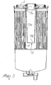
- the reference numeral 1 generally designates the outer enclosure of the filter, which has a side wall 1a and a bottom 1b and is closed in an upper region by a cover 2.
- the reference numeral 3 designates the filtering mass, which is provided in the form of rolled-up paper and is contained within a portion of space that is delimited by the side wall 1a of the outer enclosure and by a sleeve 4, which is coaxial to the enclosure, and is open onto an upper chamber 5, which lies below the cover 2 at the peripheral region of the sleeve, and onto a lower chamber 6 proximate to the bottom 1b of the enclosure.
- the Diesel fuel which flows as indicated by the arrows shown in the figure, enters the filter through connectors such as 7, which are provided in the cover 2 at peripheral regions, enters the chamber 5, and from there reaches the filtering mass 3, crossing it in a direction that is substantially parallel to the axis of the filter, and exits from it at the chamber 6, from where it rises in the sleeve 4 and exits from the filter through the output connector 8 provided at the center of the cover.
- a perforated disk 9 is provided at the base of the filtering mass 3 in order to support said mass.
- a main characteristic of the invention is the presence of means suitable to separate the water that is still present in the fuel stream that exits from the filtering mass 3; said means form a basket 10, with a side wall 10a and a bottom 10b, which is made of micromesh and comprised within the sleeve 4.
- micromesh for forming the basket 10 can be selected from a very wide commercially available range.
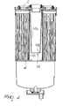
- the basket 10 protrudes from the disk 9 that is provided at the base of the filtering mass 3 and is formed monolithically therewith, for example in a single production process; the only difference of the micromesh basket 12 shown in Figure 2 with respect to the basket 10 of Figure 1 is that it rests on the disk 9 in 12a, at the lower end of the side wall.
- the end 13c of the side wall designated by the reference numerals 13a and 14a respectively, is located proximate to the cover 2 of the filter, with the bottom, designated by the reference numerals 13b and 14b respectively, located proximate to the lower end of the sleeve; while the folded end 13c of the side wall 13a is locked and interposed between the upper end of the sleeve 4 and the cover 2 and the side wall 14a of the sleeve 14 has an extension 14c formed monolithically with the sleeve 4.
- the side wall of the basket can be provided, in the various embodiments, either conical or cylindrical.
- the bottom can be either made of micromesh or solid.
- the wall of the basket can be cylindrical instead of conical and the bottom can be solid.
Landscapes
- Engineering & Computer Science (AREA)
- Chemical & Material Sciences (AREA)
- Combustion & Propulsion (AREA)
- Mechanical Engineering (AREA)
- General Engineering & Computer Science (AREA)
- Chemical Kinetics & Catalysis (AREA)
- Filtration Of Liquid (AREA)
- Cooling, Air Intake And Gas Exhaust, And Fuel Tank Arrangements In Propulsion Units (AREA)
- Separation Using Semi-Permeable Membranes (AREA)
Abstract
Description
Claims (11)
- A Diesel fuel filter comprising a substantially cylindrical outer enclosure (1a) that has a bottom (1b) and a cover (2), and is provided with a filtering mass (3) in the form of rolled-up paper contained within a portion of space that is delimited at the side walls by said outer enclosure (1a) and by a sleeve (4) that is coaxial to the enclosure (1a), is in contact in an upper region with the cover (2) and in a lower region is spaced from the bottom (1b), said sleeve (4) being open in an upper region onto a chamber (5) that lies below the cover (2) at the peripheral region of the sleeve (4) and being open, in a lower region, onto a water collection chamber (6), said filtering mass (3) being arranged as to be crossed by the fuel that enters the filter (1) through connectors (7) provided in the peripheral region of the cover (2), passes through said mass (3) with a direction that is substantially parallel to the axis of the filter (1), reaching the lower chamber (6), rises through the sleeve (4) and exits from the filter (1) through an output connector provided at the center of the cover (2), characterized in that it comprises separation means (10, 12, 13, 14) suitable to separate the water that is contained within the fuel, said separation means being provided in the form of a basket (10, 12, 13, 14) with a side wall (10a, 13a, 14a) and a bottom (10b, 13b, 14b), which is made of micromesh at least at the side wall (10a, 13a, 14a) and lies within said sleeve (4).
- The filter according to claim 1, characterized in that the side wall (10a, 13a, 14a) of the basket (10, 12) is conical.
- The filter according to claim 1, characterized in that the side wall of the basket is cylindrical.
- The filter according to one or more of the preceding claims, characterized in that the side wall (10a, 13a, 14a) and the bottom (10b, 13b, 14b) of the basket (10, 13, 14) are made of micromesh.
- The filter according to one or more of the preceding claims, characterized in that the basket (10, 12, 13, 14) has a side wall (10a, 13a, 14a) made of micromesh and a solid bottom (10b, 13b, 14b).
- The filter according to one or more of the preceding claims, characterized in that the basket (10) is an extension of a perforated disk (9) for supporting the filtering mass (3), which is provided at the lower end of the sleeve (4) and has a bottom (10b) located proximate to the upper end of said sleeve (4).
- The filter according to one or more of the preceding claims, characterized in that the basket (10) is an extension of a perforated disk (9) for supporting the filtering mass (3), which is provided at the lower end of the sleeve (4) and is formed monolithically therewith.
- The filter according to one or more of the preceding claims, characterized in that the basket (12) is an extension of a perforated disk (9) for supporting the filtering mass (3) that is present at the lower end of the sleeve (4) and rests thereon at the lower end (12a) of the side wall.
- The filter according to one or more of the preceding claims, characterized in that the end of the side wall (13a, 14a) of the basket (13, 14) is arranged proximate to the filter cover (2) and the bottom (13b, 14b) of said basket (13, 14) is located proximate to the lower end of the sleeve (4).
- The filter according to one or more of the preceding claims, characterized in that the end (13c) of the side wall (13a) of the basket (13) is arranged proximate to the filter cover (2) and is locked between the upper end of the sleeve (4) and said cover (2).
- The filter according to one or more of the preceding claims, characterized in that the end of the side wall (14a) of the basket (14) is arranged proximate to the filter cover (2) and is formed monolithically with the sleeve (4).
Applications Claiming Priority (2)
| Application Number | Priority Date | Filing Date | Title |
|---|---|---|---|
| ITMI20011255 | 2001-06-14 | ||
| IT2001MI001255A ITMI20011255A1 (en) | 2001-06-14 | 2001-06-14 | FUEL FILTER FOR DIESEL ENGINES WITH WATER SEPARATION MEANS |
Publications (2)
| Publication Number | Publication Date |
|---|---|
| EP1267068A2 true EP1267068A2 (en) | 2002-12-18 |
| EP1267068A3 EP1267068A3 (en) | 2003-11-26 |
Family
ID=11447869
Family Applications (1)
| Application Number | Title | Priority Date | Filing Date |
|---|---|---|---|
| EP02012342A Withdrawn EP1267068A3 (en) | 2001-06-14 | 2002-06-05 | Diesel fuel filter with water separation means |
Country Status (2)
| Country | Link |
|---|---|
| EP (1) | EP1267068A3 (en) |
| IT (1) | ITMI20011255A1 (en) |
Cited By (6)
| Publication number | Priority date | Publication date | Assignee | Title |
|---|---|---|---|---|
| EP1852170A1 (en) * | 2006-05-03 | 2007-11-07 | Delgrosso S.p.A. | Gas oil filter for diesel engines |
| EP1801408A3 (en) * | 2005-12-23 | 2007-11-14 | Delgrosso S.p.A. | Filter for Diesel fuel including a water separator |
| WO2008046707A1 (en) * | 2006-10-17 | 2008-04-24 | Ufi Filters S.P.A. | A filter for diesel fuel |
| DE102010031341A1 (en) * | 2010-07-14 | 2012-01-19 | Hengst Gmbh & Co. Kg | Fuel filter, particularly for internal combustion engine, has filter housing connected with filter head, where fuel inlet is connected to dirty side, and fuel outlet is connected to clean side |
| DE102011003645A1 (en) * | 2011-02-04 | 2012-08-09 | Mahle International Gmbh | Filter device for filtering liquid of internal combustion engine, particularly of motor vehicle, has filter housing with housing interior, inlet and outlet |
| FR2994858A1 (en) * | 2012-09-05 | 2014-03-07 | Filtrauto | WATER SEPARATION ARRANGEMENT AND USE OF TWO SEPARATING WATER ELEMENTS IN A FUEL FILTER |
Family Cites Families (6)
| Publication number | Priority date | Publication date | Assignee | Title |
|---|---|---|---|---|
| US4384962A (en) * | 1981-03-06 | 1983-05-24 | Stant Inc. | Fuel-water separator |
| US4477345A (en) * | 1983-01-10 | 1984-10-16 | Stant Inc. | Filter separator with heater |
| DE3440506C2 (en) * | 1984-11-06 | 1986-10-23 | Karl 6370 Oberursel Pötz | Device for separating water and contaminants from hydrocarbon fluids |
| IT1287754B1 (en) * | 1996-07-25 | 1998-08-18 | Universal Filter Spa | FUEL FILTER, IN PARTICULAR FUEL FOR DIESEL ENGINES |
| IT1316848B1 (en) * | 2000-03-24 | 2003-05-12 | Sogefi Filtration Spa | FUEL FILTER FOR DIESEL ENGINES |
| IT1316849B1 (en) * | 2000-03-24 | 2003-05-12 | Sogefi Filtration Spa | FUEL FILTER FOR DIESEL ENGINES |
-
2001
- 2001-06-14 IT IT2001MI001255A patent/ITMI20011255A1/en unknown
-
2002
- 2002-06-05 EP EP02012342A patent/EP1267068A3/en not_active Withdrawn
Cited By (7)
| Publication number | Priority date | Publication date | Assignee | Title |
|---|---|---|---|---|
| EP1801408A3 (en) * | 2005-12-23 | 2007-11-14 | Delgrosso S.p.A. | Filter for Diesel fuel including a water separator |
| EP1852170A1 (en) * | 2006-05-03 | 2007-11-07 | Delgrosso S.p.A. | Gas oil filter for diesel engines |
| WO2008046707A1 (en) * | 2006-10-17 | 2008-04-24 | Ufi Filters S.P.A. | A filter for diesel fuel |
| DE102010031341A1 (en) * | 2010-07-14 | 2012-01-19 | Hengst Gmbh & Co. Kg | Fuel filter, particularly for internal combustion engine, has filter housing connected with filter head, where fuel inlet is connected to dirty side, and fuel outlet is connected to clean side |
| DE102011003645A1 (en) * | 2011-02-04 | 2012-08-09 | Mahle International Gmbh | Filter device for filtering liquid of internal combustion engine, particularly of motor vehicle, has filter housing with housing interior, inlet and outlet |
| FR2994858A1 (en) * | 2012-09-05 | 2014-03-07 | Filtrauto | WATER SEPARATION ARRANGEMENT AND USE OF TWO SEPARATING WATER ELEMENTS IN A FUEL FILTER |
| EP2705889A1 (en) * | 2012-09-05 | 2014-03-12 | Filtrauto | Fuel filter with water separating arrangement and use of two water separating elements in a fuel filter |
Also Published As
| Publication number | Publication date |
|---|---|
| EP1267068A3 (en) | 2003-11-26 |
| ITMI20011255A1 (en) | 2002-12-14 |
| ITMI20011255A0 (en) | 2001-06-14 |
Similar Documents
| Publication | Publication Date | Title |
|---|---|---|
| EP1194207B1 (en) | Filter for diesel engine fuel | |
| KR920007873B1 (en) | Filters with flow inversion end caps suitable for flow inversion | |
| EP0185086B1 (en) | Repelling-action filter unit and assembly | |
| CA3122838C (en) | Filter arrangement including prefiltration filter element and filter device | |
| EP1267068A2 (en) | Diesel fuel filter with water separation means | |
| CN105041528A (en) | Separator element of a separator device for separating at least one fluid medium from a fluid to be treated and separator device | |
| WO2011126136A1 (en) | Filter element and filter device | |
| EP1301700B1 (en) | Diesel fuel filter with interchangeable cartridge | |
| US20030070978A1 (en) | Filter for diesel engine fuel | |
| CA2181614A1 (en) | Filter cartridge with drainable sludge barrier | |
| JPH0634722U (en) | Separation device | |
| GB2378911A (en) | Multi-stage filter assembly for gaseous, moist media | |
| KR920003762B1 (en) | Deep Filtration Filters | |
| EP1092462B1 (en) | High capacity filter | |
| CN219929868U (en) | Filter element and water purifying device | |
| JP2004195418A (en) | Liquid-liquid separating filter | |
| US4544483A (en) | Dynamic, reverse-flow oil purifier device | |
| JPH05154304A (en) | Moisture-in-oil removing filter and device | |
| RU2000131872A (en) | DEVICE FOR CLEANING NATURAL GAS FROM LIQUID | |
| EP1174075A3 (en) | Filtering unit for dishwasher | |
| CN213870084U (en) | A diesel filter with heating function | |
| CN215370083U (en) | Fuel filter element | |
| JPH046801Y2 (en) | ||
| EP0806231A2 (en) | Filter | |
| KR970069073A (en) | Photosensitive solution filtration device |
Legal Events
| Date | Code | Title | Description |
|---|---|---|---|
| PUAI | Public reference made under article 153(3) epc to a published international application that has entered the european phase |
Free format text: ORIGINAL CODE: 0009012 |
|
| AK | Designated contracting states |
Kind code of ref document: A2 Designated state(s): AT BE CH CY DE DK ES FI FR GB GR IE IT LI LU MC NL PT SE TR |
|
| AX | Request for extension of the european patent |
Free format text: AL;LT;LV;MK;RO;SI |
|
| RIN1 | Information on inventor provided before grant (corrected) |
Inventor name: TALLANO, SERGIO Inventor name: CROVETTI, CLAUDIO Inventor name: BARACCHI, PAOLO |
|
| PUAL | Search report despatched |
Free format text: ORIGINAL CODE: 0009013 |
|
| AK | Designated contracting states |
Kind code of ref document: A3 Designated state(s): AT BE CH CY DE DK ES FI FR GB GR IE IT LI LU MC NL PT SE TR |
|
| AX | Request for extension of the european patent |
Extension state: AL LT LV MK RO SI |
|
| 17P | Request for examination filed |
Effective date: 20040323 |
|
| AKX | Designation fees paid |
Designated state(s): AT BE CH CY DE DK ES FI FR GB GR IE IT LI LU MC NL PT SE TR |
|
| GRAP | Despatch of communication of intention to grant a patent |
Free format text: ORIGINAL CODE: EPIDOSNIGR1 |
|
| INTG | Intention to grant announced |
Effective date: 20141223 |
|
| STAA | Information on the status of an ep patent application or granted ep patent |
Free format text: STATUS: THE APPLICATION IS DEEMED TO BE WITHDRAWN |
|
| 18D | Application deemed to be withdrawn |
Effective date: 20150505 |