EP1267148A2 - System zur Überwachung von Wasser verbrauchenden Strukturen und deren Wärmeverbrauch in einer Einheit oder in einem mehrere Einheiten enthaltenden Gebäude, und dazugehöriges Abrechnungssystem - Google Patents
System zur Überwachung von Wasser verbrauchenden Strukturen und deren Wärmeverbrauch in einer Einheit oder in einem mehrere Einheiten enthaltenden Gebäude, und dazugehöriges Abrechnungssystem Download PDFInfo
- Publication number
- EP1267148A2 EP1267148A2 EP02077285A EP02077285A EP1267148A2 EP 1267148 A2 EP1267148 A2 EP 1267148A2 EP 02077285 A EP02077285 A EP 02077285A EP 02077285 A EP02077285 A EP 02077285A EP 1267148 A2 EP1267148 A2 EP 1267148A2
- Authority
- EP
- European Patent Office
- Prior art keywords
- water
- volumetric flow
- time
- pipe
- signal
- Prior art date
- Legal status (The legal status is an assumption and is not a legal conclusion. Google has not performed a legal analysis and makes no representation as to the accuracy of the status listed.)
- Withdrawn
Links
Images






Classifications
-
- G—PHYSICS
- G01—MEASURING; TESTING
- G01D—MEASURING NOT SPECIALLY ADAPTED FOR A SPECIFIC VARIABLE; ARRANGEMENTS FOR MEASURING TWO OR MORE VARIABLES NOT COVERED IN A SINGLE OTHER SUBCLASS; TARIFF METERING APPARATUS; MEASURING OR TESTING NOT OTHERWISE PROVIDED FOR
- G01D4/00—Tariff metering apparatus
- G01D4/002—Remote reading of utility meters
- G01D4/004—Remote reading of utility meters to a fixed location
-
- G—PHYSICS
- G01—MEASURING; TESTING
- G01F—MEASURING VOLUME, VOLUME FLOW, MASS FLOW OR LIQUID LEVEL; METERING BY VOLUME
- G01F15/00—Details of, or accessories for, apparatus of groups G01F1/00 - G01F13/00 insofar as such details or appliances are not adapted to particular types of such apparatus
- G01F15/001—Means for regulating or setting the meter for a predetermined quantity
- G01F15/003—Means for regulating or setting the meter for a predetermined quantity using electromagnetic, electric or electronic means
-
- G—PHYSICS
- G01—MEASURING; TESTING
- G01F—MEASURING VOLUME, VOLUME FLOW, MASS FLOW OR LIQUID LEVEL; METERING BY VOLUME
- G01F15/00—Details of, or accessories for, apparatus of groups G01F1/00 - G01F13/00 insofar as such details or appliances are not adapted to particular types of such apparatus
- G01F15/06—Indicating or recording devices
- G01F15/061—Indicating or recording devices for remote indication
- G01F15/063—Indicating or recording devices for remote indication using electrical means
-
- G—PHYSICS
- G01—MEASURING; TESTING
- G01F—MEASURING VOLUME, VOLUME FLOW, MASS FLOW OR LIQUID LEVEL; METERING BY VOLUME
- G01F15/00—Details of, or accessories for, apparatus of groups G01F1/00 - G01F13/00 insofar as such details or appliances are not adapted to particular types of such apparatus
- G01F15/07—Integration to give total flow, e.g. using mechanically-operated integrating mechanism
- G01F15/075—Integration to give total flow, e.g. using mechanically-operated integrating mechanism using electrically-operated integrating means
- G01F15/0755—Integration to give total flow, e.g. using mechanically-operated integrating mechanism using electrically-operated integrating means involving digital counting
-
- G—PHYSICS
- G01—MEASURING; TESTING
- G01K—MEASURING TEMPERATURE; MEASURING QUANTITY OF HEAT; THERMALLY-SENSITIVE ELEMENTS NOT OTHERWISE PROVIDED FOR
- G01K17/00—Measuring quantity of heat
- G01K17/06—Measuring quantity of heat conveyed by flowing media, e.g. in heating systems e.g. the quantity of heat in a transporting medium, delivered to or consumed in an expenditure device
-
- Y—GENERAL TAGGING OF NEW TECHNOLOGICAL DEVELOPMENTS; GENERAL TAGGING OF CROSS-SECTIONAL TECHNOLOGIES SPANNING OVER SEVERAL SECTIONS OF THE IPC; TECHNICAL SUBJECTS COVERED BY FORMER USPC CROSS-REFERENCE ART COLLECTIONS [XRACs] AND DIGESTS
- Y04—INFORMATION OR COMMUNICATION TECHNOLOGIES HAVING AN IMPACT ON OTHER TECHNOLOGY AREAS
- Y04S—SYSTEMS INTEGRATING TECHNOLOGIES RELATED TO POWER NETWORK OPERATION, COMMUNICATION OR INFORMATION TECHNOLOGIES FOR IMPROVING THE ELECTRICAL POWER GENERATION, TRANSMISSION, DISTRIBUTION, MANAGEMENT OR USAGE, i.e. SMART GRIDS
- Y04S20/00—Management or operation of end-user stationary applications or the last stages of power distribution; Controlling, monitoring or operating thereof
- Y04S20/30—Smart metering, e.g. specially adapted for remote reading
Definitions
- the present invention relates to a system for monitoring the water consumption and energy use of water consuming devices and monitoring the energy use of water operated heating and cooling devices in multi-unit building complexes where the individual units are supplied water from a common source and more particularly to a system which will calculate the water consumption and water related energy use of the individual units so that water, sewer and energy costs can be fairly apportioned to the units to encourage conservation.
- the invention also relates to monitoring unusual water usage to detect leaks and open valves.
- the individual units of a multi-unit building such as an apartment building are supplied water from a common source (the outlet of the building water meter).
- the water inlet is split into hot and cold water lines with the hot water line passing through a heater (typically there are separate hot water and heating boilers) which heat the water to the required temperature.
- a heater typically there are separate hot water and heating boilers
- multiple vertical risers supply stacked bathrooms, kitchens and heating/cooling devices. As a result the water supplied to an individual unit can not be metered without substantial, very costly, plumbing infrastructure changes.
- Utility provided water 10 generally is metered by a water meter WM 11 as it enters a building such as an apartment house or office building. A portion of the water branches off to supply the building cold water supply line 12 and the other portion is supplied to a hot water heater H 13 which supplies the hot water supply line 14 of the building.
- the building has a number of similar units (in a two story apartment house, there could be four one bedroom apartments, two on each floor, for example) each having a sink (including associated tub/shower) and toilet in the powder room and a second sink (including any associated appliances such as a dishwasher) in the kitchen.
- Each sink is supplied by separate hot and cold water lines (the hot and cold water lines of the kitchen sink may also supply a dishwasher) and each toilet is supplied by a single cold water line. Stacked kitchens and bathrooms are supplied via vertical risers 15.
- a monitor M 19 In each water line (or just downstream in the mixed water line) is located a monitor M 19.
- Figure 2 shows the heating/cooling system for the same units.
- Water hot in the winter or cold in the summer
- a suitable source such as a heat pump HP 13A (discrete sources such as a boiler for hot water and a chiller for cold water could be utilized) to a feed line 16 which supplies the individual heating or cooling units H/C 23 through multiple vertical risers 17.
- the water is returned to the source HP by suitable return lines 18.
- Located upstream and downstream of each heating or cooling unit H/C is a monitor M.
- a monitor M (fig. 3) which can be located in each line by a plumber, is a unitary battery operated structure, which is fully sealed to reduce tampering and water damage.
- the monitor can have a universal set of fittings to simplify installation.
- a monitor may include a pipe 20 in which may be permanently secured a gearbox 21 such as the type found in lawn sprinkler heads to control the movement of the water spray.
- the gear box has axial input 22 and output 24 shafts which are connected to a turbine wheel drive propeller 26 and a copper or other metal axially extending partial cylindrical portion paddle wheel 28. Water entering the pipe, passes through a set of orifices 30 which direct the water at the propeller blades thereby efficiently driving the gearbox.
- the gear ratio of the gearbox is selected so that the partial cylindrical portion 28 will make no more than about half a rotation during a sampling time (a rate of rotation that will assure that an oscillator (OSC - 25) will sense the presence of the partial cylindrical portion (the target) 28 twice each revolution).
- the gear ratio may be different for different devices (full flow for a toilet is very different than full flow for a tub, for example).
- Coil 29 will change inductance twice each revolution changing the frequency of the oscillator.
- the microprocessor uc 31 or custom specialized electronic circuit can therefore count a pulse each time the target 28 is located at 0° and 180° and each pulse equates to a unit volume of liquid.
- the gear ratio will be selected so that the target will rotate less than 180°, during one minute with maximum flow through the pipe.
- sensors such as a rotating magnet and Hall effect sensor, reed switch, capacitive sensor, optical sensor, inductive sensor with ferrite rotator, etc.
- the updated count is representative of the total volumetric flow through the pipe. Limiting the rate of rotation of the target with the gear box so that a reading need only be taken once per minute, prolongs battery life since the microprocessor uc only has to be turned on once per minute.
- the flow measuring system could also be an ultrasonic Doppler flowmeter, a magnetic flowmeter, an electronic mass flowmeter, or a vortex flowmeter, for example.
- the energy use of the hot water used in a water using device may be computed by multiplying the volumetric volume of the associated hot water pipe by the temperature that hot water is supplied where the monitor is receiving hot water from the hot water heater.
- the monitor can include a heat thermistor 32 (or a thermocouple, etc.) attached to the pipe to sense the temperature of the fluid flowing through the monitor.
- the microprocessor uc 31 may multiply the temperature by that unit volumetric flow to define a heat content number (BTU use - figure 4) and will then update the total heat content totalizator.
- the energy use of the heating/cooling unit can be determined.
- one of the monitors on either side of a heating/ cooling unit can monitor only temperature and be connected to the other monitor with that monitor making both computations such as by subtracting out the temperature reading from the other to compute the heat change. Should electrical power be available or should the battery economics permit, the position of the target could be sampled continuously and the gear box would not be required.
- the microprocessor will operate the transmitter (which is a radio transmitter 33 in the preferred embodiment but could be an ultra sonic or infrared transmitter, etc.) to transmit the then current count of the register which is representative of volumetric flow, the then current total of the heat content totalizator, identifier data which identifies the apartment unit, the water using device, etc. and any pulse count data used to chronologically locate the transmission.
- the transmitter which is a radio transmitter 33 in the preferred embodiment but could be an ultra sonic or infrared transmitter, etc.
- the microprocessor uc can also determine that a water consuming device has been left open (a tub running continuously, for example). For example, the microprocessor should detect the presence of the target once a minute while the tub is being filled at the fully open condition. Even at a slow fill rate the target should be sensed once every "X" minutes (figure 5). If "X" is five minutes, for example, the filling process should be complete within twenty minutes (four multiples of "X"). Accordingly, according to the algorithm expressed in figure 5, when the water has been running for "X" minutes and the target has been sensed, the counter is incremented and the process is repeated. When the target has been sensed in the next "X” minutes the counter again increments and so forth.
- the microprocessor will direct the transmitter to transmit an alarm signal, identifying the water consuming device, to the receiver which indicates that the device has been left open so that immediate action can be taken to correct the problem.
- the alarm signal can be transmitted to a local receiver which could be a general alarm system for the home which would announce the condition or it could be further transmitted to a remote receiver which could be at a home security company which could take appropriate action or it could be a part of the water usage system for a multiple unit building as described herein.
- This algorithm can also be computed with a number of "X” and "Y” values ("X1" and “Y1”, “X2” and “Y2”, for example) since the fill rate can be chosen at widely different rates. These variables can also be defined during installation by programming non volatile memory in the monitor.
- a radio (local) receiver (a microprocessor, for example)which can receive and decode the transmitted radio signal can be located on each floor (figure 6) for receiving the data transmitted from all of the monitors on its floor.
- the local receiver may compute daily, weekly, monthly, quarterly, etc., totals for the volumetric flow and energy (BTU) use for each unit, and can issue alarm signals (by audible alarm or telephone to a security location, for example, identifying the unit and the water consuming device subject to the alarm signal.
- Each receiver could, for example, have a visual readout or it could be connectable to a hand held terminal which can read out the data.
- the local receiver may also implement the algorithm disclosed in figure 7. It can determine a rolling volumetric flow average/unit of time ("T" may be 30 or 60 days for example) and first compare that with the calculated current volumetric flow/unit of time. Where it exceeds the rolling average by X% which indicates the a faucet is leaking, for example, the local receiver will send a maintenance signal. A second comparison can also be made to determine whether the current volumetric flow/unit of time exceeds by Y% a standard for that device. Should the difference exceed this variance, the local receiver will issue a maintenance signal.
- T rolling volumetric flow average/unit of time
- X% which indicates the a faucet is leaking
- the receiver in its simplest form, could contain an information system (or a part of a larger information system) for an individual unit or a home (figure 8).
- a monitor which would not have to monitor temperature, could be placed in each line supplying the water consuming devices so that volumetric flow data could be transmitted to a local receiver which would determine whether any device was leaking or open and would issue an appropriate alarm or maintenance signal for that device.
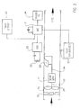
- This figure also illustrates a monitor downstream of the water meter WM - 11. This monitor can implement the algorithm of figure 5 to detect a break in any downstream water line such as could happen as a result of earthquake or freeze damage, for example.
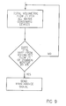
- an internal leak By comparing the volumetric flow/unit of time of this common monitor (figure 9), with the total/unit of time of all the dedicated monitors, an internal leak can be identified (a variance of X% would indicate an internal leak).
- Maintenance and alarm signals can be issued by the local receiver and optionally the local receiver can communicate with a remote receiver in the form of a security company or to the monitoring or billing system to obtain assistance..
- the multi-unit building may have a plurality of local receivers hard wired in series (or connected on a phone line) to a base local receiver (the local receiver located on the superintendents' floor for example), with the base local receiver presenting the data for all the local receivers.
- a radio custom or PCS system
- the total volumetric flow and energy use for an individual unit can be computed by each of the local receivers or all computations can be performed by the base local receiver. Alternately, such a base local receiver can be connected in parallel with the other local receivers (figure 11).
- the base receiver may not receive data from a monitor but only receive data from local receivers (receivers receiving data from monitors (figure 12).
- the base receiver is then a remote receiver.
- the remote receiver (figure 13) can provide a database which communicates via phone lines with any number of local and/or remote receivers and a receiver (a local receiver, a base local receiver or a remote receiver) can operate on the data and prepare, bills for water, energy and sewer use for each reporting unit which can be sent directly to the individual units or to the buildings for distribution as well as support reporting of leaks and open faucets, etc.
Landscapes
- Physics & Mathematics (AREA)
- General Physics & Mathematics (AREA)
- Fluid Mechanics (AREA)
- Electromagnetism (AREA)
- Engineering & Computer Science (AREA)
- Combustion & Propulsion (AREA)
- Chemical & Material Sciences (AREA)
- Measuring Volume Flow (AREA)
- Arrangements For Transmission Of Measured Signals (AREA)
- Indication And Recording Devices For Special Purposes And Tariff Metering Devices (AREA)
- Alarm Systems (AREA)
- Pipeline Systems (AREA)
- Selective Calling Equipment (AREA)
Applications Claiming Priority (9)
| Application Number | Priority Date | Filing Date | Title |
|---|---|---|---|
| US74532996A | 1996-11-08 | 1996-11-08 | |
| US745329 | 1996-11-08 | ||
| US08/745,300 US5838258A (en) | 1996-11-08 | 1996-11-08 | System for monitoring the use of heat energy in water devices in an individual unit of a multi-unit building |
| US746398 | 1996-11-08 | ||
| US745300 | 1996-11-08 | ||
| US745330 | 1996-11-08 | ||
| US08/745,330 US6377190B1 (en) | 1996-11-08 | 1996-11-08 | System for monitoring water consuming structures in an individual unit of a multi-unit building |
| US08/746,398 US6161100A (en) | 1996-11-08 | 1996-11-08 | System for billing individual units of a multi-unit building for water use and for water related energy use |
| EP97308887A EP0841546B1 (de) | 1996-11-08 | 1997-11-05 | System zur Überwachung von Wasser verbrauchenden Strukturen und deren Wärmeverbrauch in einer Einheit oder in einem mehrere Einheiten enthaltenden Gebäude, und dazugehöriges Abrechnungssystem |
Related Parent Applications (1)
| Application Number | Title | Priority Date | Filing Date |
|---|---|---|---|
| EP97308887A Division EP0841546B1 (de) | 1996-11-08 | 1997-11-05 | System zur Überwachung von Wasser verbrauchenden Strukturen und deren Wärmeverbrauch in einer Einheit oder in einem mehrere Einheiten enthaltenden Gebäude, und dazugehöriges Abrechnungssystem |
Publications (2)
| Publication Number | Publication Date |
|---|---|
| EP1267148A2 true EP1267148A2 (de) | 2002-12-18 |
| EP1267148A3 EP1267148A3 (de) | 2003-03-12 |
Family
ID=27505630
Family Applications (2)
| Application Number | Title | Priority Date | Filing Date |
|---|---|---|---|
| EP97308887A Expired - Lifetime EP0841546B1 (de) | 1996-11-08 | 1997-11-05 | System zur Überwachung von Wasser verbrauchenden Strukturen und deren Wärmeverbrauch in einer Einheit oder in einem mehrere Einheiten enthaltenden Gebäude, und dazugehöriges Abrechnungssystem |
| EP02077285A Withdrawn EP1267148A3 (de) | 1996-11-08 | 1997-11-05 | System zur Überwachung von Wasser verbrauchenden Strukturen und deren Wärmeverbrauch in einer Einheit oder in einem mehrere Einheiten enthaltenden Gebäude, und dazugehöriges Abrechnungssystem |
Family Applications Before (1)
| Application Number | Title | Priority Date | Filing Date |
|---|---|---|---|
| EP97308887A Expired - Lifetime EP0841546B1 (de) | 1996-11-08 | 1997-11-05 | System zur Überwachung von Wasser verbrauchenden Strukturen und deren Wärmeverbrauch in einer Einheit oder in einem mehrere Einheiten enthaltenden Gebäude, und dazugehöriges Abrechnungssystem |
Country Status (4)
| Country | Link |
|---|---|
| EP (2) | EP0841546B1 (de) |
| CA (1) | CA2220242A1 (de) |
| DE (1) | DE69720139T2 (de) |
| SG (2) | SG121690A1 (de) |
Cited By (1)
| Publication number | Priority date | Publication date | Assignee | Title |
|---|---|---|---|---|
| FR2865804A1 (fr) * | 2004-01-14 | 2005-08-05 | Oxel | Dispositif pour indiquer le niveau de debit de fuite d'une installation d'eau |
Families Citing this family (13)
| Publication number | Priority date | Publication date | Assignee | Title |
|---|---|---|---|---|
| US6101451A (en) * | 1998-02-23 | 2000-08-08 | Water Management Services, Inc. | Water management system |
| GB9823560D0 (en) * | 1998-10-28 | 1998-12-23 | Brulines Limited | System and method for monitoring fluid flow |
| FR2803657B1 (fr) * | 2000-01-10 | 2002-05-24 | Patrick Jourdas | Procede et dispositif de mesure fiabilisee de la quantite de fluide circulant dans une canalisation |
| FR2812084A1 (fr) * | 2000-07-20 | 2002-01-25 | Irian | Capteur transmetteur de donnees, notamment de donnees de comptage de fluide ou d'evenements ou de donnees de mesures physiques, dispositif concentrateur et procede de transmission associes |
| US6430514B1 (en) * | 2000-10-26 | 2002-08-06 | David A. Saar | Water management system |
| DE102006003333B4 (de) * | 2006-01-23 | 2013-05-29 | Hydrometer Gmbh | Selbstkonfigurierbares Verbrauchsanzeigegerät mit Funkempfänger im Heimbereich und Verfahren hierzu |
| DE102006020030A1 (de) * | 2006-04-26 | 2007-11-08 | IAD Gesellschaft für Informatik, Automatisierung und Datenverarbeitung mbH | Datenerfassungs- und Steuerungssystem mit Datenübertragung über Funkstrecken und elektrische Energieverteilnetze und Verfahren hierzu |
| US8220722B1 (en) | 2006-10-12 | 2012-07-17 | Bruce Shaffer | Thermal sensor shower monitor |
| AT509823B1 (de) * | 2010-04-15 | 2012-07-15 | Edwin Ing Ploder | System zur überwachung und steuerung des energie- und wasserhaushalts |
| US8907810B2 (en) | 2010-12-02 | 2014-12-09 | Masco Corporation | Water usage monitoring system |
| WO2013070064A1 (en) * | 2011-10-25 | 2013-05-16 | Flow Meter Group B.V. | Dual turbine gas meter |
| CN112377821A (zh) * | 2020-09-27 | 2021-02-19 | 深圳市拓邦软件技术有限公司 | 基于智能水表平台大数据的管道漏损排查方法及系统 |
| AU2022249304A1 (en) * | 2021-04-02 | 2023-10-12 | Badger Meter, Inc. | System and method for utilizing district metering areas based on meter designations |
Family Cites Families (14)
| Publication number | Priority date | Publication date | Assignee | Title |
|---|---|---|---|---|
| US3667285A (en) * | 1970-08-18 | 1972-06-06 | Customline Control Products In | Leak detection system |
| US4094194A (en) * | 1977-02-14 | 1978-06-13 | Fischer & Porter Company | Sensing system for vortex-type flowmeters |
| AT360777B (de) * | 1979-05-15 | 1981-01-26 | Benes Ewald Dipl Ing Dr | Durchflussmengenzaehler, insbesondere fuer die waermemengenmessung |
| GB2193361A (en) * | 1986-01-17 | 1988-02-03 | Ik Trading Aps | Central heating system and water system and method for controlling the tightness thereof |
| US4797666A (en) * | 1986-09-16 | 1989-01-10 | Baxter Carlton J | Method and apparatus for monitoring fluid flow |
| US4940976A (en) * | 1988-02-05 | 1990-07-10 | Utilicom Inc. | Automated remote water meter readout system |
| GB9213892D0 (en) * | 1992-06-30 | 1992-08-12 | Wheaton Roger B | Flow detecting systems |
| US5343737A (en) * | 1992-09-22 | 1994-09-06 | Joseph Baumoel | Method and apparatus for leak detection and pipeline temperature modelling method and apparatus |
| DE4235187A1 (de) * | 1992-10-19 | 1994-04-21 | Metrona Waermemesser Union | Einrichtung zum Ablesen von Verbrauchswerten in einem Gebäude anfallender Verbrauchsmengen |
| US5441070A (en) * | 1993-11-10 | 1995-08-15 | Thompson; Gary E. | Fluid management system |
| GB9404456D0 (en) * | 1994-03-08 | 1994-04-20 | Wheaton Roger B | Flow measuring and detecting systems |
| US5502652A (en) * | 1994-08-24 | 1996-03-26 | Hoggatt; Austin C. | Method and apparatus for measuring heat transfer in small diameter pipes using acoustic signals |
| DE19523666A1 (de) * | 1995-06-29 | 1997-01-02 | Stepper & Co | Verfahren zur Messung des Strömungsdurchsatzes in mit einer gemeinsamen Hauptleitung verbundenen Nebenleitungen und Leitungsnetz |
| US5568825A (en) * | 1995-12-11 | 1996-10-29 | Faulk; John W. | Automatic leak detection and shut-off system |
-
1997
- 1997-11-05 CA CA002220242A patent/CA2220242A1/en not_active Abandoned
- 1997-11-05 DE DE69720139T patent/DE69720139T2/de not_active Expired - Fee Related
- 1997-11-05 EP EP97308887A patent/EP0841546B1/de not_active Expired - Lifetime
- 1997-11-05 EP EP02077285A patent/EP1267148A3/de not_active Withdrawn
- 1997-11-06 SG SG200102641A patent/SG121690A1/en unknown
- 1997-11-06 SG SG1997003971A patent/SG71057A1/en unknown
Cited By (1)
| Publication number | Priority date | Publication date | Assignee | Title |
|---|---|---|---|---|
| FR2865804A1 (fr) * | 2004-01-14 | 2005-08-05 | Oxel | Dispositif pour indiquer le niveau de debit de fuite d'une installation d'eau |
Also Published As
| Publication number | Publication date |
|---|---|
| DE69720139T2 (de) | 2004-03-04 |
| MX9708550A (es) | 1998-06-28 |
| SG121690A1 (en) | 2006-05-26 |
| CA2220242A1 (en) | 1998-05-08 |
| DE69720139D1 (de) | 2003-04-30 |
| EP0841546B1 (de) | 2003-03-26 |
| EP1267148A3 (de) | 2003-03-12 |
| EP0841546A2 (de) | 1998-05-13 |
| SG71057A1 (en) | 1999-03-21 |
| EP0841546A3 (de) | 1999-06-16 |
Similar Documents
| Publication | Publication Date | Title |
|---|---|---|
| US6161100A (en) | System for billing individual units of a multi-unit building for water use and for water related energy use | |
| US5838258A (en) | System for monitoring the use of heat energy in water devices in an individual unit of a multi-unit building | |
| US6377190B1 (en) | System for monitoring water consuming structures in an individual unit of a multi-unit building | |
| EP0841546B1 (de) | System zur Überwachung von Wasser verbrauchenden Strukturen und deren Wärmeverbrauch in einer Einheit oder in einem mehrere Einheiten enthaltenden Gebäude, und dazugehöriges Abrechnungssystem | |
| US11047115B2 (en) | Water meter system and method | |
| US11378235B2 (en) | Method and apparatus for detecting leaks in a building water system | |
| US20210381207A1 (en) | Water meter system and method | |
| US10775213B2 (en) | Devices and system for channeling and automatic monitoring of fluid flow in fluid distribution systems | |
| US5635895A (en) | Remote power cost display system | |
| US9874466B2 (en) | Methods and apparatus for ultrasonic fluid flow measurement and fluid flow data analysis | |
| US5986573A (en) | Method and apparatus for metering building structures | |
| US20110035063A1 (en) | Water Management System | |
| WO2007053091A1 (en) | A device and a method for measurement of energy for heating tap water separated from the building's heating energy-usage . | |
| EP2450669A1 (de) | Systeme und Verfahren zur Dosierung der Verwendung eines Dienstprogramms in einem Gebäude aus mehreren Einheiten | |
| AU671123B2 (en) | Flow detecting systems | |
| US6101451A (en) | Water management system | |
| EP3279612A1 (de) | Intelligente wasserüberwachungsvorrichtung | |
| EP1411329A2 (de) | Wasserzähler | |
| US20120078538A1 (en) | Precision Fluid Flow Meter for Reduced Flows | |
| MXPA97008550A (en) | System for monitoring the structures of water consumption and its use of heat, in an individual unit of a multiple unit building, and a billing system for | |
| KR20250119829A (ko) | 기계식 수도 미터기의 누수량 표시 및 전송 장치와 이를 이용한 누수량 표시 및 전송 방법 | |
| RU15775U1 (ru) | Автоматизированная система измерения, учета и регулирования расхода теплоносителя для теплоснабжения группы потребителей | |
| EP0328885A2 (de) | Energie und Wasser-Messverfahren und Anordnung dafür | |
| Keuler et al. | Measurement and statistical evaluation of hot water tapping profiles in (non-) residential buildings | |
| Sánchez et al. | Internet of Things for a Smart Campus On Line Monitoring of Water Consumption in University Buildings |
Legal Events
| Date | Code | Title | Description |
|---|---|---|---|
| PUAI | Public reference made under article 153(3) epc to a published international application that has entered the european phase |
Free format text: ORIGINAL CODE: 0009012 |
|
| AC | Divisional application: reference to earlier application |
Ref document number: 841546 Country of ref document: EP |
|
| AK | Designated contracting states |
Kind code of ref document: A2 Designated state(s): DE FR GB IT |
|
| PUAL | Search report despatched |
Free format text: ORIGINAL CODE: 0009013 |
|
| AK | Designated contracting states |
Kind code of ref document: A3 Designated state(s): DE FR GB IT Designated state(s): DE FR GB IT |
|
| 17P | Request for examination filed |
Effective date: 20030829 |
|
| AKX | Designation fees paid |
Designated state(s): DE FR GB IT |
|
| 17Q | First examination report despatched |
Effective date: 20050419 |
|
| STAA | Information on the status of an ep patent application or granted ep patent |
Free format text: STATUS: THE APPLICATION IS DEEMED TO BE WITHDRAWN |
|
| 18D | Application deemed to be withdrawn |
Effective date: 20051102 |