EP1267444B1 - Formation de faisceaux numérique adaptatif à sous-réseaux et formation de faisceaux déterministe de somme et de différence à sensibilité réduite au brouillage et la conservation de rapport monopulse - Google Patents
Formation de faisceaux numérique adaptatif à sous-réseaux et formation de faisceaux déterministe de somme et de différence à sensibilité réduite au brouillage et la conservation de rapport monopulse Download PDFInfo
- Publication number
- EP1267444B1 EP1267444B1 EP02254213A EP02254213A EP1267444B1 EP 1267444 B1 EP1267444 B1 EP 1267444B1 EP 02254213 A EP02254213 A EP 02254213A EP 02254213 A EP02254213 A EP 02254213A EP 1267444 B1 EP1267444 B1 EP 1267444B1
- Authority
- EP
- European Patent Office
- Prior art keywords
- sub
- array
- beams
- sum
- difference
- Prior art date
- Legal status (The legal status is an assumption and is not a legal conclusion. Google has not performed a legal analysis and makes no representation as to the accuracy of the status listed.)
- Expired - Lifetime
Links
- 230000003044 adaptive effect Effects 0.000 title description 25
- 238000004321 preservation Methods 0.000 title description 5
- 238000000034 method Methods 0.000 claims description 33
- 238000003491 array Methods 0.000 claims description 24
- 238000004590 computer program Methods 0.000 claims description 7
- 238000010586 diagram Methods 0.000 description 10
- 229920000535 Tan II Polymers 0.000 description 5
- 230000006978 adaptation Effects 0.000 description 5
- 238000005259 measurement Methods 0.000 description 3
- 230000005540 biological transmission Effects 0.000 description 2
- 238000001514 detection method Methods 0.000 description 2
- 230000004044 response Effects 0.000 description 2
- 230000002238 attenuated effect Effects 0.000 description 1
- 230000007123 defense Effects 0.000 description 1
- 238000009429 electrical wiring Methods 0.000 description 1
- 230000005670 electromagnetic radiation Effects 0.000 description 1
- 239000000835 fiber Substances 0.000 description 1
- 239000011159 matrix material Substances 0.000 description 1
- 230000015654 memory Effects 0.000 description 1
- 238000005457 optimization Methods 0.000 description 1
- 238000000926 separation method Methods 0.000 description 1
- 230000001629 suppression Effects 0.000 description 1
Images


Classifications
-
- G—PHYSICS
- G01—MEASURING; TESTING
- G01S—RADIO DIRECTION-FINDING; RADIO NAVIGATION; DETERMINING DISTANCE OR VELOCITY BY USE OF RADIO WAVES; LOCATING OR PRESENCE-DETECTING BY USE OF THE REFLECTION OR RERADIATION OF RADIO WAVES; ANALOGOUS ARRANGEMENTS USING OTHER WAVES
- G01S13/00—Systems using the reflection or reradiation of radio waves, e.g. radar systems; Analogous systems using reflection or reradiation of waves whose nature or wavelength is irrelevant or unspecified
- G01S13/02—Systems using reflection of radio waves, e.g. primary radar systems; Analogous systems
- G01S13/06—Systems determining position data of a target
- G01S13/42—Simultaneous measurement of distance and other co-ordinates
- G01S13/44—Monopulse radar, i.e. simultaneous lobing
- G01S13/4463—Monopulse radar, i.e. simultaneous lobing using phased arrays
-
- G—PHYSICS
- G01—MEASURING; TESTING
- G01S—RADIO DIRECTION-FINDING; RADIO NAVIGATION; DETERMINING DISTANCE OR VELOCITY BY USE OF RADIO WAVES; LOCATING OR PRESENCE-DETECTING BY USE OF THE REFLECTION OR RERADIATION OF RADIO WAVES; ANALOGOUS ARRANGEMENTS USING OTHER WAVES
- G01S13/00—Systems using the reflection or reradiation of radio waves, e.g. radar systems; Analogous systems using reflection or reradiation of waves whose nature or wavelength is irrelevant or unspecified
- G01S13/02—Systems using reflection of radio waves, e.g. primary radar systems; Analogous systems
- G01S13/06—Systems determining position data of a target
- G01S13/42—Simultaneous measurement of distance and other co-ordinates
- G01S13/44—Monopulse radar, i.e. simultaneous lobing
- G01S13/4409—HF sub-systems particularly adapted therefor, e.g. circuits for signal combination
-
- H—ELECTRICITY
- H01—ELECTRIC ELEMENTS
- H01Q—ANTENNAS, i.e. RADIO AERIALS
- H01Q25/00—Antennas or antenna systems providing at least two radiating patterns
- H01Q25/02—Antennas or antenna systems providing at least two radiating patterns providing sum and difference patterns
-
- H—ELECTRICITY
- H01—ELECTRIC ELEMENTS
- H01Q—ANTENNAS, i.e. RADIO AERIALS
- H01Q3/00—Arrangements for changing or varying the orientation or the shape of the directional pattern of the waves radiated from an antenna or antenna system
- H01Q3/26—Arrangements for changing or varying the orientation or the shape of the directional pattern of the waves radiated from an antenna or antenna system varying the relative phase or relative amplitude of energisation between two or more active radiating elements; varying the distribution of energy across a radiating aperture
- H01Q3/2605—Array of radiating elements provided with a feedback control over the element weights, e.g. adaptive arrays
- H01Q3/2611—Means for null steering; Adaptive interference nulling
Definitions
- This invention generally relates to radar systems and techniques for determining the angular location of a target and specifically to a monopulse radar processing system and technique for maintaining the accuracy of the monopulse ratio in the presence of multiple mainlobe jammers and multiple sidelobe jammers.
- Radar systems implementing antenna arrays typically form beam patterns comprising a central beam, i.e., main lobe, and surrounding minor lobes, i.e., sidelobes.
- main lobe lobe
- minor lobes i.e., sidelobes.
- mainlobe lobe
- minor lobes i.e., sidelobes.
- mainlobe lobe
- minor lobes i.e., sidelobes.
- the mainlobe is steered toward the target of interest.
- the desired target within the mainlobe is enhanced and the response to clutter and jamming outside the mainlobe is attenuated.
- a jammer is located within the mainlobe, it becomes difficult to detect the target of interest This problem is exacerbated in the situation where multiple jammers exist
- Radar systems have been developed to cancel a single jammer in the mainlobe. Such a system is described in U.S. Patent Number 5,600,326 issued to Yu et al. However, these systems require a priori knowledge of the jammer location. Thus, a need exists for a radar system having the ability to detect a target of interest in the presence of multiple mainlobe jammers. A need also exists for a radar system having the capability to cancel multiple mainlobe jammers without requiring a priori knowledge of jammer locations. Further, a need exists for a radar system having the capability to detect a target of interest in the presence of multiple mainlobe and multiple sidelobe jammers.
- US-A-5 592 178 discloses a phased array radar system having a monopulse phased array antenna comprising a plurality of sub-arrays. Each sub-array comprises radiating elements coupled to phase shifters and attenuators. Coupled to each sub-array is a sub-array combiner for providing an azimuth difference beam ( ⁇ Az), an elevation difference beam ( ⁇ E1) and a sum beam ( ⁇ ) for precision tracking of monopulse operation.
- the sub-array combiner of a sum beam combines uniformly for each sub-array the outputs of the elements with Taylor weightings to produce a Taylor-weighted sum beam for normal mode of antenna operation or notch weightings to produce a notched sum beam for an interference suppressor mode of antenna operation.
- the sub-array combiners of an azimuth difference (or elevation difference) beam uses a Bayliss/Taylor non-uniform combiner to combiner the output of the elements with the same Taylor weightings to produce a Bayliss weighted difference beam for normal mode of antenna operation or notch weightings to produce a notched difference beam for interference suppression for each sub-array.
- Coupled to the combiners are sub-array drivers which comprise a time delay unit (TDU) with time delay control for ⁇ Az, ⁇ E1 and ⁇ for time-steering a direction of a corresponding beam of electromagnetic energy of the antenna for wideband monopulse operation.
- the sub-array drivers are coupled to monopulse receive beamformers and a transmit beamformer.
- the monopulse receive beamformers combine uniformly the corresponding TDU outputs of the sub-array drivers to simultaneously form the azimuth difference beam, the elevation difference beam and the sum beam with a wide-band notch in the direction of interference.
- the transmit beamformer distributes uniformly outputs to the sub-array driver for forming the uniformly weighted transmit beam for the maximum efficiency of a T/R module.
- One aspect of the present invention provides a method for detecting a radar target of interest in the presence of multiple radar jamming interference sources, said method comprising the steps of:
- Figure 1 is a block diagram of a conventional monopulse sub-array sum-difference beamformer
- Figure 2 is a block diagram of an exemplary adaptive digital sub-array beamformer and monopulse sum and difference beamformer, with jamming cancellation and monopulse ratio preservation, in accordance with the present invention
- Figure 3 is a block diagram of an exemplary adaptive digital sub-array beamformer and monopulse sum and difference beamformer, with jamming cancellation and monopulse ratio preservation, for a one-dimensional array, in accordance with the present invention
- Figure 4 is a flow diagram of an exemplary process for detecting a target of interest in the presence of multiple mainlobe and sidelobe jammers, in accordance with the present invention.
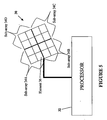
- FIG. 5 is a block diagram of an exemplary radar system in accordance with the present invention.
- Monopulse radar processing is a radar processing technique in which the angular location of a target (also referred to as direction of arrival) can be determined within fractions of a beamwidth by comparing measurements received from two or more simultaneous beams.
- This technique for estimating the direction of arrival (DOA) of a target is often implemented in surveillance and tracking radar systems comprising a phased array antenna and a digital beamforming (DBF) processor.
- DBF digital beamforming
- one beam is formed for transmission and two beams are formed upon reception for angle measurement.
- monopulse refers to the fact that the echo from a single transmitted pulse returning from a target is used to measure the angle of the target.
- Monopulse processing may be implemented for a linear array of N antenna elements which provides respective signals x(0),...,x(N-1) to a beamforming network.
- the output signals of the beamforming network are the sum, ⁇ , and difference, ⁇ , signals which are processed to generate an output signal, ⁇ , representing the estimated direction of arrival.
- the sum beam pattern has a symmetrical amplitude profile with respect to its maximum at the boresight, and the difference beam pattern has an antisymmetrical amplitude profile with respect to a zero response at the boresight.
- each of the N input signals is split into two paths, linearly weighted, and then added together.
- Monopulse processing may also be implemented for planar arrays in which the target azimuth and elevation angles are of interest.
- the sum and difference signals represent sum and difference signals for angles in elevation and azimuth. These angles are represented by the following symbols: ⁇ E represents the difference signal in elevation, ⁇ A represents the difference signal in azimuth, ⁇ represents the sum signal in elevation as well as in azimuth.
- the accuracy of the monopulse ratio, m is maintained in the presence of multiple mainlobe and multiple sidelobe interference (e.g., caused by multiple jammers).
- the accuracy of the monopulse ratio, m is maintained by adaptively suppressing the interference before forming the monopulse sum and difference output beams.
- Sub-arrays are formed using digital beamforming, DBF. Beam patterns are formed for each sub-array and jamming interference is cancelled for each sub-array by steering beam pattern nulls at the interference.
- the sub-array beam patterns are then used to form the sum, ⁇ , and difference, ⁇ , beams to determine the target DOA.
- unbiased angle estimation is achieved by exploiting the available degrees of freedom across the aperture while jamming is canceled in the sub-arrays.
- Figure 1 is a block diagram of a conventional monopulse sub-array sum-difference beamformer 100.
- Antenna array data are digitally summed by summer 2, to form a number, N, of overlapped sub-arrays.
- the amount of overlap may vary and is determined by factors such as the beamwidth of the mainlobe and available degrees of freedom in the aperture.
- Monopulse processing performance as measured by the monopulse ratio, m , is determined, in part, by sub-array separation.
- the array is partitioned into quadrants for forming respective quadrant beams in sub-array beamformer 4.
- the sub-array quadrant beams are denoted by Q 1 (T x ,T y ), Q 2 (T x ,T y ), Q 3 (T x ,T y ), and Q 4 (T x ,T y ), located at (D x ,D y ), (-D x ,D y ), (-D x ,-D y ), and (D x ,-D y ), respectively, with respect to the center of the array.
- T x and T y denote the conventional directional cosines, representing azimuth angle ( ⁇ AZ ) and elevation angle ( ⁇ EL ) information, respectively.
- Tx cos ⁇ EL ⁇ sin ( ⁇ AZ )
- Ty sin ( ⁇ EL )
- the quadrant beams differ from each other in phase.
- the quadrant beams are represented by the following equations.
- Q 1 T x ⁇ T y Q T x ⁇ T y ⁇ e j ⁇ 2 ⁇ ⁇ ⁇ ⁇ T x ⁇ D x + T y ⁇ D y
- Q 2 T x ⁇ T y Q T x ⁇ T y ⁇ e j ⁇ 2 ⁇ ⁇ ⁇ ⁇ - T x ⁇ D x + T y ⁇ D y
- Q 3 T x ⁇ T y Q T x ⁇ T y ⁇ e j ⁇ 2 ⁇ ⁇ ⁇ - T x ⁇ D x - T y ⁇ D y
- Q 4 T x ⁇ T y Q T x ⁇ T y ⁇ e j
- the quadrant beams are summed, by the monopulse sum-difference beamformer 6, to form the sum, ⁇ (T x ,T y ), azimuth difference, ⁇ A (T x ,T y ), and elevation difference, ⁇ E (T x ,T y ), outputs in accordance with the following equations.
- adaptive processing techniques are implemented to reduce interference due to jamming.
- Various adaptive processing techniques may be implemented depending upon the number of available antenna element data. Examples of adaptive processing techniques include a main auxiliary adaptation technique, an adaptive-adaptive processing technique, and a fully adaptive array technique.
- main beam and auxiliary beams are formed from available array elements, which are capable of being shared among multiple beams.
- the auxiliary beams are used to cancel the sidelobe jamming in the sum beam.
- the auxiliary beams are steered in the direction of the jammers.
- the auxiliary beams are used to cancel jamming in the sum beam.
- all elements of the array are used to cancel jamming while the sum beam is formed from all elements of the array.
- the adaptive processing can be formulated using the sub-array degrees of freedom (i.e., the number of elements available in the sub-array) to cancel jamming subject to the constraint of sub-array bore-sight gain.
- the jammer power is minimized.
- jammer power is minimized subject to a constraint of maintaining sub-array boresight gain.
- J 1 W 1 H ⁇ R 11 ⁇ W 1 - ⁇ ⁇ S 1 H ⁇ W 1 - g 1 , where ⁇ is the LaGrange multiplier for constrained optimization.
- W 2 R 22 - 1 ⁇ S 2 S 2 H ⁇ R 22 - 1 ⁇ S 2 ⁇ g 2
- W 3 R 33 - 1 ⁇ S 3 S 3 H ⁇ R 33 - 1 ⁇ S 3 ⁇ g 3
- W 4 R 44 - 1 ⁇ S 4 S 4 H ⁇ R 44 - 1 ⁇ S 4 ⁇ g 4 .
- FIG. 2 is a block diagram of an exemplary system 200 including adaptive digital sub-array beamformer 8 and monopulse processor 34, with jamming cancellation and monopulse ratio preservation, in accordance with the present invention.
- Antenna element data are formed into sub-arrays by summer 2, and the sub-array data are provided to adaptive sub-array beamformer 8.
- Adaptive sub-array beamformer 8 forms beam patterns for each sub-array, with nulls adaptively located (steered) to suppress jamming interference. The nulls may be steered in the direction of jamming interference as a result of the adaptation.
- Adapted or estimated values are represented by placing a circumflex (" ⁇ ") over the estimated variable or quantity.
- the adaptive beam pattern formed from elements of each sub-array result in identical nulls responsive to mainlobe or sidelobe jammers.
- the adaptive sub-array beams can also be related to a common adaptive sub-array beam located at the center of the array ( Q ⁇ (T x ,T y )).
- the estimated quadrant beams are represented by the following equations.
- the estimated sub-array beams are provided to the monopulse sum and difference beamformer 10.
- Monopulse sum and difference beamformer 10 provides estimated sum, and difference beams in elevation and azimuth, ⁇ ( T x , T y ), ⁇ E ( T x , T y ), and ⁇ A ( T x , T y ), respectively, to monopulse ratio former 34.
- Monopulse ratio former 34 calculates the monopulse ratio in azimuth and elevation in accordance with the following equations.
- the jamming is cancelled by the adaptive sub-array beamformer 8, using the spatial degrees of freedom of each sub-array (i.e., the number of available elements in each sub-array) to steer at least one null of each sub-array beam toward the jamming interference.
- the spatial degrees of freedom across the sub-arrays i.e., the number of available elements in the total array
- Figure 3 is a block diagram of an exemplary adaptive digital sub-array beamformer and monopulse processor, with jamming cancellation and monopulse ratio preservation, for a one-dimensional array, in accordance with the present invention.
- Processing for the one-dimensional array is similar to that of the two-dimensional array, except that the beam patterns are in one less dimension in the one-dimensional array implementation than in the two-dimensional array implementation.
- the estimated adaptive processing is applied to sub-arrays which differ by a linear phase factor.
- Sub-array data are provided to one-dimensional adaptive sub-array beamformer 12.
- Estimated sub-array beams (i.e., ⁇ A 1 ( T x ), ⁇ A 2 ( T x ), ⁇ A 3 ( T x ), and ⁇ A 4 ( T x )) are formed by one-dimensional adaptive sub-array beamformer 12, in which the nulls are adaptively located to suppress jammer interference.
- the nulls may be steered in the direction of jamming interference as a result of adaptation.
- the estimated sub-array beams are provided to monopulse sum and difference beamformer 14.
- Monopulse sum and difference beamformer 14 forms estimated sum and difference beams (i.e., ⁇ ( T x ) and ⁇ ( T x )), which are use to calculate the monopulse ratio, m ⁇ , in monopulse ratio former 36, in accordance with the following equation.
- ⁇ ( T x ) and ⁇ ( T x ) are use to calculate the monopulse ratio, m ⁇ , in monopulse ratio former 36, in accordance with the following equation.
- the unbiased monopulse angle estimate is given by the following equation.
- a radar processing system and technique utilizing the versatility of digital beamforming to form sub-arrays for canceling jamming interference, and adaptively suppressing jamming interference prior to using conventional deterministic methods (i.e., equations (24) and (25)) to form the sum, ⁇ , and difference, ⁇ , beams for monopulse processing provide the ability to detect a target of interest, provide an undistorted monopulse ratio, m , and maintain target angle estimation, in the presence of multiple mainlobe and multiple sidelobe jammers. Further, this system and technique are not constrained by requiring a priori knowledge of the jamming interference.
- FIG. 4 is a flow diagram of an exemplary process for detecting a target of interest and maintaining a monopulse ratio in the presence of multiple mainlobe jammers and multiple sidelobe jammers in accordance with the present invention.
- Sub-arrays are formed using digital beamforming, from the full antenna array in step 16.
- Antenna array element data are digitally summed to form the sub-arrays.
- Step 16 may be performed by summer 2 of Figure 1.
- the amount that the sub-arrays overlap (share the same antenna element data) is discretionary. Factors to consider when determining which antenna elements are assigned to the various sub-arrays include the desired beamwidth of each sub-array, the degrees of freedom available for adaptive processing, and the impact on monopulse processing performance parameters.
- sub-array beams are adaptively formed for each sub-array.
- Each sub-array beam pattern comprises a mainlobe and at least one null.
- four quadrant sub-arrays are formed.
- Nulls are adaptively formed to suppress jammer interference by multiplying sub-array element data by the adaptively formed weights formed in accordance with equations (16), (17), (18), and (19).
- the adaptively formed sub-array beam patterns are in accordance with equations (20), (21), (22), and (23). At least one null of each sub-array beam pattern is adaptively steered toward the jamming interference, while the boresight gain of each sub-array beam pattern is maintained.
- Monopulse sum, and difference beams in elevation and azimuth, ⁇ ( T x , T y ), ⁇ E ( T x , T y ), and ⁇ A ( T x ,T y ), respectively, are determined using the full antenna array element data in step 24.
- Monopulse ratios are determined in step 26, in accordance with equations (24) and (25), to provide undistorted monopulse ratios m ⁇ A and m ⁇ E .
- the monopulse ratios are used to determine the estimated angle of arrival of the target of interest. This may be accomplished through the use of a look up table or from extracting data from a plot of monopulse ratio versus arrival angle.
- the monopulse ratio is maintained in step 28 by updating the sub-array beam patterns to steer the null(s) toward the jamming interference.
- the sum and difference beams are recalculated using the updated beam patterns, and updated monopulse ratios are calculated to maintain the accuracy of the estimated arrival angle.
- FIG. 5 is a block diagram of a radar system comprising an antenna array 30 and computer processor 32 in accordance with an exemplary embodiment of the invention.
- the exemplary array 30 has four sub-arrays 34A, 34B, 34C, and 34D, each sub-array including a plurality of antenna elements 36.
- Data received by antenna array 30 is transmitted to computer processor 32.
- Computer processor 32 performs processes for detecting a target of interest and maintaining a monopulse ratio in the presence of multiple mainlobe jammers and multiple sidelobe jammers in accordance with the present invention, as herein described with reference to Figure 4.
- Received signal processing may also be performed by special purpose hardware.
- the present invention may also be embodied in the form of computer program code embodied in tangible media, such as floppy diskettes, read only memories (ROMs), CD-ROMs, hard drives, high density disk, or any other computer-readable storage medium, wherein, when the computer program code is loaded into and executed by computer processor 32, a radar system comprising an antenna array 30 and the computer processor 32, becomes an apparatus for practicing the invention.
- tangible media such as floppy diskettes, read only memories (ROMs), CD-ROMs, hard drives, high density disk, or any other computer-readable storage medium
- the present invention may also be embodied in the form of computer program code, for example, whether stored in a storage medium, loaded into and/or executed by computer processor 32, or transmitted over some transmission medium, such as over electrical wiring or cabling, through fiber optics, or via electromagnetic radiation, wherein, when the computer program code is loaded into and executed by computer processor 32, a radar system comprising an antenna array 30 and the computer processor 32, becomes an apparatus for practicing the invention.
- the computer program code segments configure the processor to create specific logic circuits.
Landscapes
- Engineering & Computer Science (AREA)
- Radar, Positioning & Navigation (AREA)
- Remote Sensing (AREA)
- Computer Networks & Wireless Communication (AREA)
- Physics & Mathematics (AREA)
- General Physics & Mathematics (AREA)
- Radar Systems Or Details Thereof (AREA)
- Variable-Direction Aerials And Aerial Arrays (AREA)
Claims (7)
- Procédé de détection d'une cible radar visée en présence de multiples sources d'interférence de brouillage radar, ce procédé comprenant les étapes suivantes :former (16) une pluralité de sous-réseaux à partir d'un réseau d'antenne ;former numériquement (18) des faisceaux de données de sous-réseaux à partir de la pluralité de sous-réseaux et produire des faisceaux de sous-réseaux en quadrants, chacun étant associé à un motif de faisceau de sous-réseau respectif pour chacun de la pluralité de sous-réseaux, et chaque faisceau de sous-réseau en quadrant ayant des zéros à des positions de zéros identiques, les faisceaux de sous-réseaux formés ayant une contrainte de maintien de gain de visée donné de chaque faisceau de sous-réseau en quadrant ;orienter (18) les zéros associés aux faisceaux de sous-réseaux en quadrant dans des directions associées aux sources d'interférence ;déterminer (24) des faisceaux de somme et de différence à partir de la pluralité de faisceaux de sous-réseaux pour détecter la cible concernée ; etdéterminer (26, 28) un rapport de mono-impulsion sur la base des faisceaux de somme et de différence ; etestimer un angle d'arrivée de la cible en utilisant le rapport de mono-impulsion.
- Procédé selon la revendication 1, dans lequel les faisceaux de différence sont déterminés en azimut et en élévation.
- Procédé selon la revendication 1, dans lequel l'étape de formation numérique de faisceau de données de sous-réseau à partir de la pluralité de sous-réseaux et de génération de faisceaux de sous-réseaux en quadrants comprend la formation adaptative des motifs de faisceau de sous-réseau.
- Procédé selon la revendication 1, comprenant en outre l'étape consistant à maintenir un angle d'arrivée estimé de la cible concernée, l'étape de maintien comprenant :mettre à jour chaque faisceau de sous-réseau en quadrant pour orienter un zéro de chaque motif de faisceau de sous-réseau vers une source d'interférence et maintenir un gain de visée de chaque motif de faisceau de sous-réseau ;déterminer des faisceaux mis à jour de somme et de différence à partir des faisceaux de sous-réseaux mis à jour ; etdéterminer au moins un rapport de mono-impulsion mis à jour à partir des faisceaux mis à jour de somme et de différence pour maintenir un angle estimé d'arrivée de la cible concernée.
- Système radar pour détecter une cible radar concernée en présence de multiples sources d'interférence, le système comprenant un réseau d'antenne (30) et un processeur (32), dans lequel le processeur est agencé pour mettre en oeuvre le procédé de l'une quelconque des revendications 1 à 4.
- Programme d'ordinateur comprenant un code d'ordinateur qui, quand il est chargé dans un système informatique, amène le système à mettre en oeuvre le procédé de l'une quelconque des revendications 1 à 4.
- Milieu lisible par un ordinateur mémorisant un programme d'ordinateur selon la revendication 6.
Applications Claiming Priority (2)
| Application Number | Priority Date | Filing Date | Title |
|---|---|---|---|
| US882348 | 2001-06-15 | ||
| US09/882,348 US6661366B2 (en) | 2001-06-15 | 2001-06-15 | Adaptive digital sub-array beamforming and deterministic sum and difference beamforming, with jamming cancellation and monopulse ratio preservation |
Publications (3)
| Publication Number | Publication Date |
|---|---|
| EP1267444A2 EP1267444A2 (fr) | 2002-12-18 |
| EP1267444A3 EP1267444A3 (fr) | 2004-03-31 |
| EP1267444B1 true EP1267444B1 (fr) | 2007-02-21 |
Family
ID=25380401
Family Applications (1)
| Application Number | Title | Priority Date | Filing Date |
|---|---|---|---|
| EP02254213A Expired - Lifetime EP1267444B1 (fr) | 2001-06-15 | 2002-06-17 | Formation de faisceaux numérique adaptatif à sous-réseaux et formation de faisceaux déterministe de somme et de différence à sensibilité réduite au brouillage et la conservation de rapport monopulse |
Country Status (3)
| Country | Link |
|---|---|
| US (1) | US6661366B2 (fr) |
| EP (1) | EP1267444B1 (fr) |
| DE (1) | DE60218244T2 (fr) |
Families Citing this family (52)
| Publication number | Priority date | Publication date | Assignee | Title |
|---|---|---|---|---|
| US6930637B2 (en) * | 2001-11-15 | 2005-08-16 | Texas Instruments Incorporated | Method and apparatus for high resolution tracking via mono-pulse beam-forming in a communication system |
| US6738018B2 (en) * | 2002-05-01 | 2004-05-18 | Harris Corporation | All digital phased array using space/time cascaded processing |
| US20040157645A1 (en) * | 2003-02-12 | 2004-08-12 | Smith Adrian David | System and method of operation an array antenna in a distributed wireless communication network |
| US7099696B2 (en) * | 2003-02-14 | 2006-08-29 | Radio Frequency Systems, Inc. | Angle diversity dual antenna system |
| US7136012B2 (en) * | 2003-04-01 | 2006-11-14 | Lockheed Martin Corporation | Approach radar with array antenna having rows and columns skewed relative to the horizontal |
| US7183974B1 (en) | 2004-05-21 | 2007-02-27 | Itt Manufacturing Enterprises, Inc. | Methods and apparatus for increasing the effective resolving power of array antennas |
| JP4665590B2 (ja) * | 2005-03-31 | 2011-04-06 | 日本電気株式会社 | 干渉型レーダ |
| US20080068266A1 (en) * | 2005-11-23 | 2008-03-20 | Northrop Grumman Corporation | Beamforming for spatial sidelobe cancellation and AMR direction finding |
| US7843376B1 (en) * | 2006-12-27 | 2010-11-30 | Lockheed Martin Corporation | Cross-eye jamming detection and mitigation |
| CN101520507B (zh) * | 2007-07-20 | 2012-03-21 | 通用汽车环球科技运作公司 | 低成本近程雷达 |
| US7671789B1 (en) * | 2008-10-03 | 2010-03-02 | Lockheed Martin Corporation | Method and system for target detection and angle estimation based on a radar signal |
| KR101668785B1 (ko) * | 2009-12-01 | 2016-10-24 | 사브 에이비 | 스캐닝 레이더 시스템의 신호를 각도 포커싱하는 방법 |
| US8269665B1 (en) * | 2010-01-29 | 2012-09-18 | Lockheed Martin Corporation | Monopulse angle determination |
| US8736484B2 (en) * | 2010-08-11 | 2014-05-27 | Lockheed Martin Corporation | Enhanced-resolution phased array radar |
| JP5634278B2 (ja) * | 2011-01-25 | 2014-12-03 | 株式会社東芝 | ウェイト算出方法、ウェイト算出装置、アダプティブアレーアンテナ、及びレーダ装置 |
| US8199851B1 (en) * | 2011-07-14 | 2012-06-12 | The Aerospace Corporation | Systems and methods for increasing communications bandwidth using non-orthogonal polarizations |
| US8593334B2 (en) * | 2011-07-29 | 2013-11-26 | The Boeing Company | Split aperture monopulse antenna system |
| US8947294B1 (en) * | 2011-11-02 | 2015-02-03 | Lockheed Martin Corporation | Method and system for adaptively cancelling clutter from the sidelobes of a ground-based radar |
| US9275690B2 (en) | 2012-05-30 | 2016-03-01 | Tahoe Rf Semiconductor, Inc. | Power management in an electronic system through reducing energy usage of a battery and/or controlling an output power of an amplifier thereof |
| US9509351B2 (en) | 2012-07-27 | 2016-11-29 | Tahoe Rf Semiconductor, Inc. | Simultaneous accommodation of a low power signal and an interfering signal in a radio frequency (RF) receiver |
| TWI457585B (zh) * | 2012-12-11 | 2014-10-21 | Univ Nat Chiao Tung | 角度偵測方法及其裝置 |
| US9666942B2 (en) | 2013-03-15 | 2017-05-30 | Gigpeak, Inc. | Adaptive transmit array for beam-steering |
| US9184498B2 (en) | 2013-03-15 | 2015-11-10 | Gigoptix, Inc. | Extending beamforming capability of a coupled voltage controlled oscillator (VCO) array during local oscillator (LO) signal generation through fine control of a tunable frequency of a tank circuit of a VCO thereof |
| US9531070B2 (en) | 2013-03-15 | 2016-12-27 | Christopher T. Schiller | Extending beamforming capability of a coupled voltage controlled oscillator (VCO) array during local oscillator (LO) signal generation through accommodating differential coupling between VCOs thereof |
| US9722310B2 (en) | 2013-03-15 | 2017-08-01 | Gigpeak, Inc. | Extending beamforming capability of a coupled voltage controlled oscillator (VCO) array during local oscillator (LO) signal generation through frequency multiplication |
| US9780449B2 (en) | 2013-03-15 | 2017-10-03 | Integrated Device Technology, Inc. | Phase shift based improved reference input frequency signal injection into a coupled voltage controlled oscillator (VCO) array during local oscillator (LO) signal generation to reduce a phase-steering requirement during beamforming |
| US9716315B2 (en) | 2013-03-15 | 2017-07-25 | Gigpeak, Inc. | Automatic high-resolution adaptive beam-steering |
| US9837714B2 (en) | 2013-03-15 | 2017-12-05 | Integrated Device Technology, Inc. | Extending beamforming capability of a coupled voltage controlled oscillator (VCO) array during local oscillator (LO) signal generation through a circular configuration thereof |
| US9288007B2 (en) * | 2013-11-15 | 2016-03-15 | At&T Intellectual Property I, L.P. | Endpoint device antenna beam forming based jamming detection and mitigation |
| US9772402B2 (en) * | 2014-06-09 | 2017-09-26 | Src, Inc. | Multiplatform GMTI radar with adaptive clutter suppression |
| US9502766B2 (en) * | 2014-07-25 | 2016-11-22 | Raytheon Company | Electronically reconfigurable, piecewise-linear, scalable analog monopulse network |
| US9285469B1 (en) * | 2014-10-29 | 2016-03-15 | Src, Inc. | Multiplatform GMTI radar with enhanced SNR, monopulse |
| US9917377B2 (en) * | 2015-02-02 | 2018-03-13 | Mitsubishi Electric Corporation | Antenna device and antenna excitation method |
| FR3042929A1 (fr) * | 2015-10-23 | 2017-04-28 | Commissariat Energie Atomique | Antenne a reseau transmetteur pour systeme radar mono-impulsion |
| CN106226749B (zh) * | 2016-07-01 | 2018-11-16 | 西安电子科技大学 | 基于空时自适应处理雷达的和差波束形成方法 |
| CN108919203B (zh) * | 2018-05-21 | 2022-04-22 | 西安电子科技大学 | 一种雷达有源干扰的识别方法及系统 |
| CN110045361A (zh) * | 2019-02-28 | 2019-07-23 | 西南电子技术研究所(中国电子科技集团公司第十研究所) | 球面相控阵单脉冲数字跟踪系统 |
| US11181614B2 (en) * | 2019-06-06 | 2021-11-23 | GM Global Technology Operations LLC | Antenna array tilt and processing to eliminate false detections in a radar system |
| CN110554387B (zh) * | 2019-09-04 | 2021-04-09 | 中国科学院电子学研究所 | 综合孔径干涉近场主动源成像方法和装置 |
| CN110988835B (zh) * | 2019-11-27 | 2023-03-31 | 中国船舶重工集团公司第七二四研究所 | 一种分布式相参雷达测角方法 |
| CN111123250B (zh) * | 2019-12-30 | 2021-09-28 | 成都汇蓉国科微系统技术有限公司 | 基于模式搜索算法的脉冲多普勒雷达和波束形成方法 |
| US11846699B2 (en) * | 2020-01-16 | 2023-12-19 | United States Of America As Represented By The Secretary Of The Navy | Method for monopulse single beam phased array tracking for communications using beam jitter |
| WO2021188024A1 (fr) * | 2020-03-18 | 2021-09-23 | Telefonaktiebolaget Lm Ericsson (Publ) | Amélioration du niveau de lobe latéral dans une antenne réseau |
| CN112904297B (zh) * | 2021-01-19 | 2024-02-13 | 南京理工大学 | 一种分维自适应单脉冲波束形成与角度估计方法 |
| CN112986995B (zh) * | 2021-02-06 | 2021-10-01 | 中国人民解放军战略支援部队航天工程大学 | 一种基于递归结构波束形成的二维成像方法及系统 |
| CN113050045B (zh) * | 2021-02-09 | 2022-02-22 | 中国人民解放军空军研究院战略预警研究所 | 一种智能化综合抗主副瓣干扰系统及方法 |
| WO2022182869A1 (fr) | 2021-02-24 | 2022-09-01 | Bluehalo Llc | Système et procédé d'alimentation de réseau à commande de phase à formation de faisceau numérique |
| CN113820653B (zh) * | 2021-08-04 | 2023-05-09 | 西安电子科技大学 | 基于动态和差波束的米波雷达低仰角目标doa估计方法 |
| CN113625063B (zh) * | 2021-08-04 | 2024-01-02 | 上海无线电设备研究所 | 一种整机条件下的天线单脉冲性能评估方法 |
| CN114397620B (zh) * | 2022-01-04 | 2024-06-07 | 西安电子科技大学 | 改进和差非均匀阵列的高精度波达方向估计方法 |
| CN114488142B (zh) * | 2022-02-08 | 2024-12-10 | 中国人民解放军战略支援部队航天工程大学 | 一种基于差-和波束的雷达二维角成像方法及系统 |
| US12546855B2 (en) * | 2023-05-23 | 2026-02-10 | Rockwell Collins, Inc. | AESA-based synthetic nulling for enhanced radar ground clutter suppression |
Family Cites Families (13)
| Publication number | Priority date | Publication date | Assignee | Title |
|---|---|---|---|---|
| US4214244A (en) | 1971-12-20 | 1980-07-22 | Martin Marietta Corporation | Null pattern technique for reduction of an undesirable interfering signal |
| US4225870A (en) | 1978-05-10 | 1980-09-30 | The United States Of America As Represented By The Secretary Of The Army | Null steering antenna |
| US5173702A (en) * | 1980-12-29 | 1992-12-22 | Raytheon Company | All weather tactical strike system (AWTSS) and method of operation |
| US5185608A (en) * | 1980-12-29 | 1993-02-09 | Raytheon Company | All weather tactical strike system (AWISS) and method of operation |
| US4298873A (en) | 1981-01-02 | 1981-11-03 | The United States Of America As Represented By The Secretary Of The Army | Adaptive steerable null antenna processor |
| FR2527785A1 (fr) * | 1982-05-27 | 1983-12-02 | Thomson Csf | Procede et dispositif de reduction de la puissance des signaux de brouillage recus par les lobes lateraux d'une antenne radar |
| US4555706A (en) | 1983-05-26 | 1985-11-26 | Unidet States Of America Secr | Simultaneous nulling in the sum and difference patterns of a monopulse radar antenna |
| US5600326A (en) | 1991-12-16 | 1997-02-04 | Martin Marietta Corp. | Adaptive digital beamforming architecture and algorithm for nulling mainlobe and multiple sidelobe radar jammers while preserving monopulse ratio angle estimation accuracy |
| US5371506A (en) | 1993-07-19 | 1994-12-06 | General Electric Co. | Simultaneous multibeam approach for cancelling multiple mainlobe jammers while preserving monopulse angle estimation accuracy on mainlobe targets |
| US5592178A (en) * | 1994-06-01 | 1997-01-07 | Raytheon Company | Wideband interference suppressor in a phased array radar |
| US5515060A (en) | 1995-05-11 | 1996-05-07 | Martin Marietta Corp. | Clutter suppression for thinned array with phase only nulling |
| US6084540A (en) | 1998-07-20 | 2000-07-04 | Lockheed Martin Corp. | Determination of jammer directions using multiple antenna beam patterns |
| US6087974A (en) | 1998-08-03 | 2000-07-11 | Lockheed Martin Corporation | Monopulse system for target location |
-
2001
- 2001-06-15 US US09/882,348 patent/US6661366B2/en not_active Expired - Fee Related
-
2002
- 2002-06-17 DE DE60218244T patent/DE60218244T2/de not_active Expired - Lifetime
- 2002-06-17 EP EP02254213A patent/EP1267444B1/fr not_active Expired - Lifetime
Also Published As
| Publication number | Publication date |
|---|---|
| US20030020646A1 (en) | 2003-01-30 |
| EP1267444A2 (fr) | 2002-12-18 |
| DE60218244D1 (de) | 2007-04-05 |
| US6661366B2 (en) | 2003-12-09 |
| EP1267444A3 (fr) | 2004-03-31 |
| DE60218244T2 (de) | 2007-11-08 |
Similar Documents
| Publication | Publication Date | Title |
|---|---|---|
| EP1267444B1 (fr) | Formation de faisceaux numérique adaptatif à sous-réseaux et formation de faisceaux déterministe de somme et de différence à sensibilité réduite au brouillage et la conservation de rapport monopulse | |
| US6697009B2 (en) | Adaptive digital beamforming architecture for target detection and angle estimation in multiple mainlobe and sidelobe jamming | |
| US5600326A (en) | Adaptive digital beamforming architecture and algorithm for nulling mainlobe and multiple sidelobe radar jammers while preserving monopulse ratio angle estimation accuracy | |
| US6084540A (en) | Determination of jammer directions using multiple antenna beam patterns | |
| US5371506A (en) | Simultaneous multibeam approach for cancelling multiple mainlobe jammers while preserving monopulse angle estimation accuracy on mainlobe targets | |
| EP1159635B1 (fr) | Systeme radar a eliminateurs et suppresseurs de bluffeurs | |
| EP1167995B1 (fr) | Processeur monopulse pour déterminer l'angle d'azimuth et d'élévation de deux cibles utilisant une matrice de rapports d'amplitudes | |
| US6867726B1 (en) | Combining sidelobe canceller and mainlobe canceller for adaptive monopulse radar processing | |
| US7136012B2 (en) | Approach radar with array antenna having rows and columns skewed relative to the horizontal | |
| US5311192A (en) | Polarization ECCM technique for radar systems | |
| US6720910B2 (en) | Pri-staggered post-doppler adaptive monopulse processing for detection and location of a moving target in ground clutter | |
| US20030184473A1 (en) | Adaptive digital sub-array beamforming and deterministic sum and difference beamforming, with jamming cancellation and monopulse ratio preservation | |
| Feng et al. | Target localization using MIMO-monopulse: Application on 79 GHz FMCW automotive radar | |
| US4121209A (en) | Two-axis motion compensation for AMTI | |
| US20210119348A1 (en) | Array antenna apparatus using spatial power spectrum combining and method of controlling the same | |
| Zhuang et al. | Application of frequency diversity to suppress grating lobes in coherent MIMO radar with separated subapertures | |
| US6369746B1 (en) | Simultaneous nulling in low sidelobe sum and difference antenna beam patterns | |
| JP2005189107A (ja) | レーダ装置 | |
| CN113406620B (zh) | 一种阵列分解的分布式阵列测角方法 | |
| Milin et al. | AMSAR-A European success story in AESA radar | |
| Ruan et al. | A Joint Design of Sparse Array Layout and DOA Algorithm for mmWave FMCW Radar | |
| KR20210046545A (ko) | 공간 전력 스펙트럼 결합을 이용한 배열 안테나 장치 및 그 제어 방법 | |
| Yu | Enhanced monopulse angle estimation using 4-channel radar system | |
| JP4834508B2 (ja) | レーダ装置 | |
| Yu | Mainlobe cancellation, orthogonal nulling and product patterns |
Legal Events
| Date | Code | Title | Description |
|---|---|---|---|
| PUAI | Public reference made under article 153(3) epc to a published international application that has entered the european phase |
Free format text: ORIGINAL CODE: 0009012 |
|
| AK | Designated contracting states |
Kind code of ref document: A2 Designated state(s): AT BE CH CY DE DK ES FI FR GB GR IE IT LI LU MC NL PT SE TR |
|
| AX | Request for extension of the european patent |
Free format text: AL;LT;LV;MK;RO;SI |
|
| PUAL | Search report despatched |
Free format text: ORIGINAL CODE: 0009013 |
|
| AK | Designated contracting states |
Kind code of ref document: A3 Designated state(s): AT BE CH CY DE DK ES FI FR GB GR IE IT LI LU MC NL PT SE TR |
|
| AX | Request for extension of the european patent |
Extension state: AL LT LV MK RO SI |
|
| 17P | Request for examination filed |
Effective date: 20040916 |
|
| AKX | Designation fees paid |
Designated state(s): DE FR GB IT |
|
| 17Q | First examination report despatched |
Effective date: 20050215 |
|
| GRAP | Despatch of communication of intention to grant a patent |
Free format text: ORIGINAL CODE: EPIDOSNIGR1 |
|
| GRAS | Grant fee paid |
Free format text: ORIGINAL CODE: EPIDOSNIGR3 |
|
| GRAA | (expected) grant |
Free format text: ORIGINAL CODE: 0009210 |
|
| AK | Designated contracting states |
Kind code of ref document: B1 Designated state(s): DE FR GB IT |
|
| REG | Reference to a national code |
Ref country code: GB Ref legal event code: FG4D |
|
| REF | Corresponds to: |
Ref document number: 60218244 Country of ref document: DE Date of ref document: 20070405 Kind code of ref document: P |
|
| ET | Fr: translation filed | ||
| PLBE | No opposition filed within time limit |
Free format text: ORIGINAL CODE: 0009261 |
|
| STAA | Information on the status of an ep patent application or granted ep patent |
Free format text: STATUS: NO OPPOSITION FILED WITHIN TIME LIMIT |
|
| 26N | No opposition filed |
Effective date: 20071122 |
|
| PGFP | Annual fee paid to national office [announced via postgrant information from national office to epo] |
Ref country code: FR Payment date: 20100630 Year of fee payment: 9 |
|
| PGFP | Annual fee paid to national office [announced via postgrant information from national office to epo] |
Ref country code: IT Payment date: 20100624 Year of fee payment: 9 |
|
| PGFP | Annual fee paid to national office [announced via postgrant information from national office to epo] |
Ref country code: DE Payment date: 20100629 Year of fee payment: 9 Ref country code: GB Payment date: 20100625 Year of fee payment: 9 |
|
| GBPC | Gb: european patent ceased through non-payment of renewal fee |
Effective date: 20110617 |
|
| PG25 | Lapsed in a contracting state [announced via postgrant information from national office to epo] |
Ref country code: IT Free format text: LAPSE BECAUSE OF NON-PAYMENT OF DUE FEES Effective date: 20110617 |
|
| REG | Reference to a national code |
Ref country code: FR Ref legal event code: ST Effective date: 20120229 |
|
| REG | Reference to a national code |
Ref country code: DE Ref legal event code: R119 Ref document number: 60218244 Country of ref document: DE Effective date: 20120103 |
|
| PG25 | Lapsed in a contracting state [announced via postgrant information from national office to epo] |
Ref country code: DE Free format text: LAPSE BECAUSE OF NON-PAYMENT OF DUE FEES Effective date: 20120103 Ref country code: FR Free format text: LAPSE BECAUSE OF NON-PAYMENT OF DUE FEES Effective date: 20110630 |
|
| PG25 | Lapsed in a contracting state [announced via postgrant information from national office to epo] |
Ref country code: GB Free format text: LAPSE BECAUSE OF NON-PAYMENT OF DUE FEES Effective date: 20110617 |