EP1267607B1 - Vorrichtung und verfahren zur entnahme von milchproben - Google Patents
Vorrichtung und verfahren zur entnahme von milchproben Download PDFInfo
- Publication number
- EP1267607B1 EP1267607B1 EP01918087A EP01918087A EP1267607B1 EP 1267607 B1 EP1267607 B1 EP 1267607B1 EP 01918087 A EP01918087 A EP 01918087A EP 01918087 A EP01918087 A EP 01918087A EP 1267607 B1 EP1267607 B1 EP 1267607B1
- Authority
- EP
- European Patent Office
- Prior art keywords
- milk
- sampling apparatus
- collecting elements
- sample collecting
- milk sample
- Prior art date
- Legal status (The legal status is an assumption and is not a legal conclusion. Google has not performed a legal analysis and makes no representation as to the accuracy of the status listed.)
- Revoked
Links
- 239000008267 milk Substances 0.000 title claims abstract description 185
- 235000013336 milk Nutrition 0.000 title claims abstract description 185
- 210000004080 milk Anatomy 0.000 title claims abstract description 185
- 238000005070 sampling Methods 0.000 title claims abstract description 87
- 238000000034 method Methods 0.000 title claims abstract description 27
- 241001465754 Metazoa Species 0.000 claims abstract description 17
- 238000004140 cleaning Methods 0.000 claims description 15
- 238000004891 communication Methods 0.000 claims description 11
- 239000012530 fluid Substances 0.000 claims description 8
- 238000012545 processing Methods 0.000 claims description 8
- 230000004044 response Effects 0.000 claims description 8
- 239000003755 preservative agent Substances 0.000 description 14
- 230000002335 preservative effect Effects 0.000 description 14
- 230000005540 biological transmission Effects 0.000 description 8
- 238000013461 design Methods 0.000 description 7
- 241000894006 Bacteria Species 0.000 description 4
- 230000006870 function Effects 0.000 description 4
- 230000008901 benefit Effects 0.000 description 3
- 230000000977 initiatory effect Effects 0.000 description 3
- 238000009434 installation Methods 0.000 description 3
- 238000012360 testing method Methods 0.000 description 3
- LVDKZNITIUWNER-UHFFFAOYSA-N Bronopol Chemical compound OCC(Br)(CO)[N+]([O-])=O LVDKZNITIUWNER-UHFFFAOYSA-N 0.000 description 2
- 238000013019 agitation Methods 0.000 description 2
- 238000010586 diagram Methods 0.000 description 2
- 230000005484 gravity Effects 0.000 description 2
- 238000002347 injection Methods 0.000 description 2
- 239000007924 injection Substances 0.000 description 2
- 239000000463 material Substances 0.000 description 2
- 210000002445 nipple Anatomy 0.000 description 2
- 229910000831 Steel Inorganic materials 0.000 description 1
- XSQUKJJJFZCRTK-UHFFFAOYSA-N Urea Chemical compound NC(N)=O XSQUKJJJFZCRTK-UHFFFAOYSA-N 0.000 description 1
- 230000001133 acceleration Effects 0.000 description 1
- 238000013459 approach Methods 0.000 description 1
- 238000007664 blowing Methods 0.000 description 1
- 229960003168 bronopol Drugs 0.000 description 1
- 239000004202 carbamide Substances 0.000 description 1
- 230000000295 complement effect Effects 0.000 description 1
- 238000010276 construction Methods 0.000 description 1
- 238000011109 contamination Methods 0.000 description 1
- 235000013365 dairy product Nutrition 0.000 description 1
- 238000013016 damping Methods 0.000 description 1
- 230000003247 decreasing effect Effects 0.000 description 1
- 238000009826 distribution Methods 0.000 description 1
- 238000012423 maintenance Methods 0.000 description 1
- 238000005259 measurement Methods 0.000 description 1
- 230000007246 mechanism Effects 0.000 description 1
- 238000012986 modification Methods 0.000 description 1
- 230000004048 modification Effects 0.000 description 1
- 239000004033 plastic Substances 0.000 description 1
- 230000008569 process Effects 0.000 description 1
- 102000004169 proteins and genes Human genes 0.000 description 1
- 108090000623 proteins and genes Proteins 0.000 description 1
- 229910001220 stainless steel Inorganic materials 0.000 description 1
- 239000010935 stainless steel Substances 0.000 description 1
- 239000010959 steel Substances 0.000 description 1
- 230000001360 synchronised effect Effects 0.000 description 1
Images


Classifications
-
- G—PHYSICS
- G01—MEASURING; TESTING
- G01N—INVESTIGATING OR ANALYSING MATERIALS BY DETERMINING THEIR CHEMICAL OR PHYSICAL PROPERTIES
- G01N1/00—Sampling; Preparing specimens for investigation
- G01N1/02—Devices for withdrawing samples
- G01N1/10—Devices for withdrawing samples in the liquid or fluent state
- G01N1/18—Devices for withdrawing samples in the liquid or fluent state with provision for splitting samples into portions
-
- A—HUMAN NECESSITIES
- A01—AGRICULTURE; FORESTRY; ANIMAL HUSBANDRY; HUNTING; TRAPPING; FISHING
- A01J—MANUFACTURE OF DAIRY PRODUCTS
- A01J5/00—Milking machines or devices
- A01J5/04—Milking machines or devices with pneumatic manipulation of teats
- A01J5/045—Taking milk-samples
-
- B—PERFORMING OPERATIONS; TRANSPORTING
- B01—PHYSICAL OR CHEMICAL PROCESSES OR APPARATUS IN GENERAL
- B01L—CHEMICAL OR PHYSICAL LABORATORY APPARATUS FOR GENERAL USE
- B01L9/00—Supporting devices; Holding devices
- B01L9/06—Test-tube stands; Test-tube holders
-
- G—PHYSICS
- G01—MEASURING; TESTING
- G01N—INVESTIGATING OR ANALYSING MATERIALS BY DETERMINING THEIR CHEMICAL OR PHYSICAL PROPERTIES
- G01N33/00—Investigating or analysing materials by specific methods not covered by groups G01N1/00 - G01N31/00
- G01N33/02—Food
- G01N33/04—Dairy products
-
- G—PHYSICS
- G01—MEASURING; TESTING
- G01N—INVESTIGATING OR ANALYSING MATERIALS BY DETERMINING THEIR CHEMICAL OR PHYSICAL PROPERTIES
- G01N35/00—Automatic analysis not limited to methods or materials provided for in any single one of groups G01N1/00 - G01N33/00; Handling materials therefor
- G01N35/10—Devices for transferring samples or any liquids to, in, or from, the analysis apparatus, e.g. suction devices, injection devices
- G01N35/1081—Devices for transferring samples or any liquids to, in, or from, the analysis apparatus, e.g. suction devices, injection devices characterised by the means for relatively moving the transfer device and the containers in an horizontal plane
- G01N35/109—Devices for transferring samples or any liquids to, in, or from, the analysis apparatus, e.g. suction devices, injection devices characterised by the means for relatively moving the transfer device and the containers in an horizontal plane with two horizontal degrees of freedom
-
- Y—GENERAL TAGGING OF NEW TECHNOLOGICAL DEVELOPMENTS; GENERAL TAGGING OF CROSS-SECTIONAL TECHNOLOGIES SPANNING OVER SEVERAL SECTIONS OF THE IPC; TECHNICAL SUBJECTS COVERED BY FORMER USPC CROSS-REFERENCE ART COLLECTIONS [XRACs] AND DIGESTS
- Y10—TECHNICAL SUBJECTS COVERED BY FORMER USPC
- Y10T—TECHNICAL SUBJECTS COVERED BY FORMER US CLASSIFICATION
- Y10T436/00—Chemistry: analytical and immunological testing
- Y10T436/25—Chemistry: analytical and immunological testing including sample preparation
- Y10T436/2575—Volumetric liquid transfer
Definitions
- the present invention generally relates to dairy farm machine milking and to milk sampling related thereto.
- the invention relates to a milk sampling apparatus for use with an automated milking system and to a method for sampling of milk from said automated milking system.
- the milk is drawn from the teats of the animal by means of teat cups connected to vacuum.
- the milk is drawn through a milk tube and into a flow meter wherein the amount of milk is measured.
- the milk is further transported to a storing tank or similar wherein it is stored together with milk from other animals while waiting for a milk lorry to collect it.
- the milk sampling is typically performed in connection with milking of the animals by employing a milk sampling device provided with a fixed or removable cassette wherein milk test tubes can be placed, and with a filling member connected to the milking system and capable of filling the respective tubes with milk from the respective animals.
- a milk sampling device provided with a fixed or removable cassette wherein milk test tubes can be placed, and with a filling member connected to the milking system and capable of filling the respective tubes with milk from the respective animals.
- the laboratory equipment is adapted to the cassettes and test tubes that are used by the farmers served by that laboratory. Further, laboratory equipment, cassettes and test tubes, vary quite much from country to country.
- sample tubes are typically prepared with a preservative prior to milk sampling, which preservative shall restrain the milk from turning to sour before the samples have been delivered to the laboratory and been analyzed.
- This preservative is to be dissolved in the milk, which typically takes a period of time, during which the increase of bacteria in the milk speeds up, whereby the risk that the milk turns to sour increases.
- EP 0 564 023 A1 (LELY/MAASLAND).
- This device is provided with a cassette formed as a rotating box in which, along its circumference, milk sample collecting elements can be arranged.
- the filling member is disposed in a fixed position, while the collecting elements can be placed successively under the filling member.
- the filling member is further provided with a vertically movable type of injection needle to be inserted into the collecting elements.
- the cassette and the injection needle have to be moved synchronously, which requires specific measures to be taken.
- Another prior art milk sampling device is depicted in EP 0 749 681 A1 (LELY/MAASLAND).
- This device is provided with a removable cassette in which milk sample collecting elements can be placed, and at least one filling member capable of being placed successively above various collecting elements and bringing milk samples, taken from milk provided by an automatic milking machine, to the respective collecting elements.
- Guide means is provided for supporting the filling member such that the filling member is moved, by successively increasing and decreasing the distance between the guide means and the cassette, from a position above a collecting element to an adjacent position above a nearby situated collecting element. In such manner the filling member may step from collecting element to collecting element along a predetermined fixed zigzag formed closed path.
- This device has a simple design, but the movement of the filling member is not flexible since it is determined by said fixed path. This may be a major drawback if a single collecting element is to be used for collecting a second non-consecutive sample, e.g. for sampling a cow a second time a number of hours later, as the guide means may have to step through a relatively long path before reaching the collecting element in question.
- a further drawback of both these prior art milk sampling devices is that they are designed to fit only one cassette size. As there exist different standards of cassettes and sample collecting elements in different countries a device has to be manufactured in various designs if it is to be put on several markets.
- EP 0 494 066 A2 describes a milk sampling apparatus comprising a box wherein a number of cassettes are arranged side by side. Each cassette houses a single row of sample collecting elements, which together constitute a fixed integral sample unit.
- the apparatus comprises a position transmitter for identifying the position of each sample collecting element; and a movable filling member for filling each sample collecting element with milk. Further, each cassette carries a support marking and along the supports there are row markings for the collecting element positions within the row. Reading devices read the position of each sample collecting element when being filled, which position via the position transmitter is forwarded to a computer.
- a milk sample taken can be matched with the supplier of the milk by virtue of the identification and position of the sample collecting element.
- the sampling apparatus of EP 0 494 066 lacks the capability of bringing a milk sample to a selected milk collecting element
- a milk sampling apparatus and method that comprise a flexible filling member movement capability, wherein the filling member can be automatically positioned above a milk sample collecting element placed in a cassette of the apparatus, independently of where the collecting element is placed in the cassette, e.g. by just providing the coordinates for the position of the collecting element.
- the flexible positioning is obtained by means of a positioning system, which makes use of the movement mechanism of a conventional XY recorder, for moving the filling member in a plane above the cassette.
- the positioning system comprises an arm extending in a first direction, or Y direction, in the plane and being movable in a second direction, or X direction, in said plane.
- a runner is further provided, at which the filling member is mounted, the runner being movable along the arm.
- two drive means preferably servo-operated motors, are provided.
- the drive means are effective to position the filling member at said location.
- the drive means are effective to move the arm in the second direction (X) in response to a first provided signal value or a first provided number of pulses; and to move the runner along the arm (Y direction) in response to a second provided signal value or a second provided number of pulses.
- a major advantage of the invention is that it provides for a very flexible use, particularly as regards the movement of the filling member. Indeed, the filling member may be directly moved to any desired position (in terms of position coordinates) above the cassette, thus not unduly restricting the movement of the filling member to predetermined positions along a predetermined path.
- a further advantage of the invention is the usability with a large range of cassette and sample collecting element designs and sizes, i.a. due to the variable movement capability of the flexible filling member.
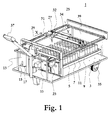
- Fig. 1 displays schematically an embodiment of a milk sampling apparatus according to the present invention.
- Figs. 2a-d illustrate four different embodiments of an XY-positioning system as being included in the milk sampling apparatus of Fig. 1.
- Fig. 3 is a schematic block diagram of an embodiment of the milk sampling apparatus according to the present invention connected to an automated milking system, the sampling apparatus being adapted for two-way communication with the milking system.
- Fig. 4 illustrate an embodiment of a shaking table as being included in the milk sampling apparatus of Fig. 1.
- an embodiment of a milk sampling apparatus 1 comprises a stainless steel chassis 3 at which a shaking or vibrating table 5 is mounted.
- a stirring or vibrating table 5 At table 5 one, or preferably two, cassettes 7 are removably mounted, in which cassette(s) milk sample collecting elements or tubes 9 are placed. Tubes 9 are arranged vertically with their openings pointing upwards.
- a rubber sheet or insert 11 may be provided at the upper surface of table 5 having a punched through opening, wherein cassette(s) 7 can be arranged. The opening is made such that a close fit between cassette(s) 7 and rubber sheet 11 is obtained.
- Sheet 11 is preferably about 25 mm thick and may be of any other suitable material such as e.g. steel. The provision of rubber sheet 11 allows for possibilities to tailor-make the sampling apparatus to fit with a particular cassette or a particular practice or standard.
- chassis 3, shaking table 5 and rubber sheet 11 are preferably such that there is room for two conventional German sample cassettes, which are the largest cassettes the present inventors have found on the market. In such a cassette there is room for 70 sample tubes and 140 sample tubes will probably be sufficient in order to handle 50 milking animals during a period of 24 hours if each animal yields one sample per milking. If a single sample tube may be used more than one time for a given animal that presents for milking during the 24 hours interval, the milk sample device can handle even more animals or, alternatively, the number of sample tubes may be reduced.
- the milk sampling apparatus comprises a collection vessel 13, which can be arranged in fluid connection with a milk passage, e.g. vessel or conduit, of an automated milking station to which the milk sampling apparatus is connectable via adjustment of a valve (not shown in Fig. 1).
- a milk passage e.g. vessel or conduit
- collection vessel 13 is by means of a vacuum supplied hose connected to a likewise vacuum supplied flow meter of the automated milking system, through which flow meter all milk as drawn from a milking animal is passed.
- a representative milk amount typically about 2 % (corresponding to about half a liter) of the total milk amount from a milking, is by way of gravity flowed into collection vessel 13 when a sample is to be taken.
- the hose has in a preferred embodiment an inner diameter of 10 mm and a thickness of material of about 3 mm.
- Collection vessel 13 is also connected to a source of compressed air via a pressure regulator (not shown in Fig. 1) for the supply of air.
- two different discharge outlets are arranged at different heights of collection vessel 13, of which the upper outlet 15 is connected to a discharge line (not shown in Fig. 1) and the lower outlet 17, being located at bottom of vessel 13, is via a conduit connected to a hose (not shown in Fig. 1) arranged in a spring biased reel 23.
- the milk sampling apparatus of Fig. 1 comprises further a servo-operated XY-positioning system or table 25 arranged parallel with and above cassette(s) 7.
- XY-positioning system 25 is a device adapted for flexible positioning of a filling member 27 above a selected one of the plurality of sample tubes in cassette(s) 7.
- XY-positioning system 25 comprises two servo systems 29, 31, of which a first moves an arm 34 in the X-direction such that the position of the arm is proportional to a first provided signal value (e.g. a voltage) or a first provided number of pulses.
- a first provided signal value e.g. a voltage
- the filling member being connected to the hose of hose reel 23, is mounted on a runner 32 that is movable along the arm in the Y-direction such that the position of runner 32 and filling member 27 is proportional to a second provided signal value (e.g. voltage) or a second provided number of pulses.
- a second provided signal value e.g. voltage
- the operation is thus similar to a conventional XY recorder.
- a processing means 33 is provided for two-way communication with the automated milking system, which will be further depicted below with reference to Fig. 3. Processing means 33 controls the position of the filling member as well as all valves included in the apparatus.
- All valves are preferably of hose clamping kind such that no pockets or spaces, where dirt and bacteria may settle, exists.
- the hose clamps are preferably electro-mechanical, wherein the hose is pinched by means of a spring and opened by means of an electromagnet. Pneumatic valves may alternatively be used.
- the milk sampling apparatus may preferably be provided with wheels 35 and a handle 37, such that the apparatus may easily be transported by the farmer.
- the apparatus comprises also a cover 39 to protect from dirt, the cover being preferably transparent such that the operation of the apparatus may be observed by the farmer.
- the apparatus is designed such that the distance between the cassette and the floor is large and the handling of the sample tubes takes place from above. In such an instance the risk of contamination of the samples is minimized and a good hygiene is safeguarded.
- a simple and low cost implementation of the transmission of force is the use of synchronous transmission or drive belts 41. Using such transmission a reliable design, which require no maintenance, is achieved. The precision is not excellent, but acceptable for the present purpose.
- the force the transmission has to cope with, is only the tension force from the hose reel and any occurring friction.
- FIG. 2b An alternative implementation, shown in Fig. 2b, uses linear rails with runners.
- the transmission of the runners is realized by means of gear racks 43 along rails 44, 45 and motors 29, 31 mounted on respective runners 46, 47, wherein rail 44 is firmly mounted on runner 47.
- the performance of this implementation would be similar to that of the implementation of Fig. 2a.
- One drawback using this implementation is that more cords must be flexible and movable.
- a further alternative, shown in Fig. 2c, is implementing a rotatable trapezoid threaded screw 49 and a runner or nut 50 for transmission, gearing, and load carrying in the X direction, said runner being prevented from being rotated.
- the movement in the Y direction is realized by a wire 51, which is journalled 53 at runner 50 and is attached to a further runner 54, which in turn is attached to a biased slidable spring 55.
- the spring 55 and the end of wire 51 attached to the spring may be considered to constitute arm 34 of Fig. 1.
- a still further alternative implementation shown in Fig. 2d, uses a respective rotatable screw 56 and a respective runner 57 for transmission, gearing, and load carrying in the respective direction.
- weak step motors may be used.
- Fig. 3 is a schematic block diagram of the inventive milk sampling apparatus including a two-way communication interface to the automated milking system, said milk sampling apparatus, and particularly the function thereof, will be further described.
- an initiating signal from a processing means 59 of automated milking system 61 is via line 63 sent to processing means 33 of milk sampling apparatus 1 together with XY coordinates for the sample tube to be used for the current sample.
- Processor 33 sends a control signal to open valve 65 and a representative fraction of milk from a milking, is then by way of gravity flowed from automated milking system 61, through conduit 67 and into collection vessel 13. At this point all other valves 69, 71, 73 are closed. Meanwhile processor 33 sends control signals to servo systems 29, 31 instructing them to move filling member 27 to the coordinates as received from automated milking system 61.
- valve 71 is opened by processor 33 such that a major portion of the milk is evacuated through line 77.
- the milk left in vessel 13 is given by the cross sectional area of vessel 13 and the height at which outlet 15 is arranged.
- a typical volume is 8-16 ml.
- the evacuated milk may be thrown away, recirculated to automated milking system 61, or transported to e.g. a milk storage tank (not shown in Fig. 3).
- Valve 71 is closed and valve 73 is opened. At this time the filling member is at place at the given coordinates, i.e. above the selected sample tube.
- the milk sample is flowed out of outlet 17, through a conduit 19 and a hose 21, and out through the orifice of filling member 27, and finally collected in the selected sample tube.
- the air is blown for a period of time such that it is safeguarded that the entire milk sample has been transferred to the sample tube.
- the vertical distance between the orifice of filling member 27 and the upper end of the sample tube has to be small enough to secure that the entire milk sample will be collected in the correct tube.
- processor 33 sends a signal to a motor 79, which shakes shaking table 5 and thus the sample tubes, see further the description with reference to Fig. 4 below.
- microprocessor 33 sends a completion message to automated milking system via line 81.
- valves and all motors are controlled by means of processor 33, which is indicated by control lines 83.
- processor 33 is preferably provided with a memory, suitable software and a power supply (not shown in Fig. 3). Also, the motors and valves are power supplied in any suitable manner.
- the milk sampling apparatus is provided with a battery for the supplying of power, and thus no electrical connections have to be made at the installation of the apparatus.
- the flexible function of the milk sampling apparatus implies that the filling of the sample tubes may be performed in any order.
- the filling member may be directly moved to any desired position (in terms of position coordinates) above the cassette. Hence, no undue restriction of the movement of the filling member to predetermined positions along a predetermined path is imposed.
- a single sample tube is to be used also for collecting a second non-consecutive sample, e.g. for sampling a cow a second time some hours later, it is readily done simply by instructing the servo systems of the XY-positioning system to move the filling member to the coordinates in question.
- Cleaning of all parts of the milk sampling apparatus 1 that come into contact with milk may easily be performed by using the conventional cleaning of the automated milking system.
- valves 65 and 73 By providing a drain outlet below any suitable XY coordinate position and by moving the filling member 27 to this position cleaning is simply performed by opening valves 65 and 73 (and possibly by opening a valve (not shown) at the automated milking station side of conduit 67) and letting the cleaning fluid pass through line 67, vessel 13, lines 19, 21 and filling member 27 and be discharged through said drain outlet.
- Valve 73 may be repeatedly closed and opened during the cleaning process such that vessel 13 becomes repeatedly entirely filled with cleaning fluid to enhance cleaning of vessel 13.
- Valve 69 may be opened such that compressed air is mixed with the cleaning fluid and if it is desirable to also clean line 77, valve 71 is opened.
- cleaning fluid may be supplied through line 77 by means of connecting it to a pump and a cleaning fluid supply (not shown in Fig. 3).
- drain outlet channels can be arranged along one or more sides of the milk sampling apparatus. If such channels are arranged along all sides filling member 27 has never to be moved more than half the width of the milk sampling apparatus.
- Communication from the automated milking station to the milk sample apparatus may preferably include various kinds of control commands and interrogation and information messages, whereas communication in the opposite direction include various kinds of information and alarm messages.
- Communication from the automated milking station to the milk sampling apparatus may particularly include any of:
- Communication from the milk sampling apparatus to the automated milking station may particularly include any of:
- FIG. 4 illustrates an embodiment of shaking table 5 as being part of the milk sampling apparatus 1 of Fig. 1, this aspect of the invention will be described closer.
- the sample tubes are typically prepared with a preservative prior to milk sampling, which preservative shall restrain the milk from turning to sour before the samples have been delivered to the laboratory and been analyzed.
- This preservative is to be dissolved in the milk.
- Such dissolving typically takes a certain period of time, during which the increase of bacteria in the milk speeds up, and thus the risk that the milk turns to sour increases.
- the sample tubes are typically delivered to the farmer in a cleaned and preservative prepared condition.
- the preservative may be 2-bromo-2-nitropropane-1,3-diol, also widely commercially available under the trademark BRONOPOL, which is crystallized in the bottom of the tubes.
- the cassette with the prepared sample tubes are typically to be used during a 24 hours period of time, which implies that that the tubes are standing for such a period in the milk sampling apparatus in a milk farm environment without any individual covers. It is under such circumstances desirable to safeguard a fast dissolving of the preservative in the milk.
- the shaking table 5 of the milk sampling apparatus according to the present invention is thus used to accelerate this dissolving by shaking sample tubes 9.
- the shaking table in Fig. 4 is arranged on chassis 3 of Fig. 1 by means of four elastic isolator feet 85, preferably made of rubber or plastic, of which only two are indicated in Fig. 4.
- Two cassettes 7 with sample tubes 9 are arranged on shaking table 5 as schematically illustrated in Fig. 4.
- the table 5 is being shaken by means of motor 79 rotating an eccentric disk 83.
- the shaking table 5 can be moved in two transverse directions (X and Y directions) and rotated around a third axis, the Z axis, being perpendicular to X and Y dimensions.
- the shaking operation may be affected by the mutual placement of various parts of the milk sampling apparatus such as shaking table, motor, eccentric disk, cassette, sample tubes and elastic isolator feet. Furthermore, the weights and weight distributions of the eccentric disk and of the shaking table may be altered. System constants such as rotation speed of the eccentric disk, spring constant and damping constant of the elastic isolator feet may also be altered. All these parameters affect the shaking function and thus a number of actions may be taken in order to properly design the shaking table to yield an appropriate agitation of the samples.
- Other shaking tables that may be used in the present invention are disclosed in U.S. Patent Nos. 4,102,649 and 5,259,672, which patents hereby are incorporated by reference.
- the preservative has partly or completely become dissolved after about an hour, but this may in some applications be a too long period of time since the growth of bacteria has started.
- the dissolving of preservative in milk is strongly accelerated.
- shaking is performed subsequent to each taken milk sample.
- dissolving acceleration means may be used as a complement or instead of the shaking table, such as ultrasonic devices or any other suitable agitating means known in the art.
- a representative small amount (e.g. 8-16 ml) of milk can be sampled directly from the automated milking system, see e.g. U.S. Patent No. 5,303,598.
- collection vessel 13 of Fig. 1 may be dispensed with and a small portion of milk (typically in the order of 10 -4 of the total amount of milk) may be flowed from the automated milking system, through a hose and a filling member, and into a sample tube, preferably during the entire time of the milking of an animal in order to obtain a representative sample.
Landscapes
- Life Sciences & Earth Sciences (AREA)
- Health & Medical Sciences (AREA)
- Chemical & Material Sciences (AREA)
- General Physics & Mathematics (AREA)
- Pathology (AREA)
- Analytical Chemistry (AREA)
- Biochemistry (AREA)
- General Health & Medical Sciences (AREA)
- Hydrology & Water Resources (AREA)
- Immunology (AREA)
- Physics & Mathematics (AREA)
- Clinical Laboratory Science (AREA)
- Chemical Kinetics & Catalysis (AREA)
- Animal Husbandry (AREA)
- Environmental Sciences (AREA)
- Sampling And Sample Adjustment (AREA)
- Dairy Products (AREA)
Claims (34)
- Milchproben-Entnahmevorrichtung zur Verwendung mit einem automatisierten Melksystem, die eine Kassette (7), in der Milchproben-Sammelelemente (9) angeordnet sind, und zumindest ein Einfüllelement (27) aufweist, das geeignet ist, oberhalb eines ausgewählten der Milchproben-Sammelelemente (9) durch ein Positioniersystem angeordnet zu werden und eine Milchprobe, die repräsentativ aus der Milch genommen wird, die während des Melkens eines Tieres durch das automatisierte Melksystem erhalten wird, in das Ausgewählte der Milchproben-Sammelelemente (9) zu bringen, wobei das Positioniersystem Folgendes aufweist:dadurch gekennzeichnet, dasseinen Arm (34, 44, 56, 51, 55), der sich in eine erste Richtung (Y) in einer Ebene (XY) oberhalb der Milchproben-Sammelelemente (9) erstreckt und in eine zweite Richtung (X) in der Ebene (XY) beweglich ist, wobei die erste (Y) und die zweite (X) Richtung orthogonal sind;einen ersten Läufer (32, 46, 54, 57), der das Einfüllelement (27) hält und entlang des Armes (34) beweglich ist underste (29) und zweite (31) Antriebseinrichtungen vorgesehen sind, wobeidie erste Antriebseinrichtung bewirkt, den Arm in die zweite Richtung (X) als Antwort auf einen ersten bereitgestellten Signalwert oder eine erste bereitgestellte Pulsanzahl zu bewegen, und die zweite Antriebseinrichtung bewirkt, den ersten Läufer entlang des Armes (Y-Richtung) als Antwort auf einen zweiten bereitgestellten Signalwert oder eine zweite bereitgestellte Pulsanzahl zu bewegen, um das Einfüllelement (27) oberhalb des Ausgewählten der Milchproben-Sammelelemente (9) anzuordnen.
- Milchproben-Entnahmevorrichtung nach Anspruch 1, bei der die ersten und zweiten Antriebseinrichtung jeweils einen Servo-betriebenen Motor (29, 31) aufweisen.
- Milchproben-Entnahmevorrichtung nach Anspruch 1 oder 2, bei der eine der ersten und zweiten Antriebseinrichtung die Bewegung durch einen Antriebsriemen (41) bewirkt.
- Milchproben-Entnahmevorrichtung nach Anspruch 1, bei der die erste Antriebseinrichtung einen ersten Servo-betriebenen Motor (29) aufweist, der zusammen mit dem Arm (44) fest an einem zweiten Läufer (47) befestigt ist, und der zweite Läufer durch einen ersten Motor bewegt wird, der mit einer ersten Zahnstange (43) zusammenwirkt.
- Milchproben-Entnahmevorrichtung nach Anspruch 4, bei der die zweite Antriebseinrichtung einen zweiten Servo-betriebenen Motor (31) aufweist, der fest an dem ersten Läufer (46) befestigt ist, und der erste Läufer durch einen zweiten Motor bewegt wird, der mit einer zweiten Zahnstange (43) zusammenwirkt.
- Milchproben-Entnahmevorrichtung nach Anspruch 2, bei der der Arm (34) an einem zweiten Läufer (50, 57) befestigt ist, der auf eine Schraube (49, 56) geschraubt und an einer Drehung gehindert ist, und bei der der Motor (29) der ersten Antriebseinrichtung bewirkt, den Arm (56, 51, 55) durch Drehen der Schraube zu bewegen.
- Milchproben-Entnahmevorrichtung nach Anspruch 6, bei der der erste Läufer (57) auf eine zweite Schraube (56) geschraubt und an einer Drehung gehindert ist, und bei der der Motor (31) der zweiten Antriebseinrichtung an dem zweiten Läufer befestigt ist und bewirkt, den ersten Läufer (57) durch Drehen der zweiten Schraube zu bewegen.
- Milchproben-Entnahmevorrichtung nach Anspruch 6, bei der der erste Läufer (54) durch eine Feder (55) vorgespannt ist und die zweite Antriebseinrichtung (31) bewirkt, den ersten Läufer durch einen Antriebsdraht (51) zu bewegen.
- Milchproben-Entnahmevorrichtung nach einem der Ansprüche 1 bis 8, die durch das Positioniersystem fähig ist, eine zweite nicht-fortlaufende Milchprobe, die repräsentativ aus der Milch genommen wird, die während eines zweiten Melkens des Tieres durch das automatisierte Melksystem erhalten wird, in das Ausgewählte der Milchproben-Sammelelemente (9) zu bringen.
- Milchproben-Entnahmevorrichtung nach einem der Ansprüche 1 bis 9, bei der die Kassette durch eine Einlage (11) an der Stelle gehalten wird.
- Milchproben-Entnahmevorrichtung nach Anspruch 10, bei der die Einlage (11) eine Öffnung aufweist, in die die Kassette hineinpasst.
- Milchproben-Entnahmevorrichtung nach Anspruch 10 oder 11, die eine zweite Kassette (7) aufweist, in der Milchproben-Sammelelemente (9) angeordnet sind, und bei der die zweite Kassette durch die Einlage (11) an der Stelle gehalten wird, und bei der das zumindest eine Einfüllelement (27) fähig ist, oberhalb eines Ausgewählten der Milchproben-Sammelelemente (9) in der zweiten Kassette (7) angeordnet zu werden.
- Milchproben-Entnahmevorrichtung nach einem der Ansprüche 1 bis 12, bei der der vertikale Abstand zwischen dem Einfüllelement (27) und dem oberen Ende des Ausgewählten der Milchproben-Sammelelemente (9) gering ist, wenn das Einfüllelement (27) oberhalb des Ausgewählten der Milchproben-Sammelelemente (9) angeordnet ist, um sicherzustellen, dass die Milchprobe in das Ausgewählte der Milchproben-Sammelelemente (9) in ihrer Gesamtheit eingebracht wird.
- Milchproben-Entnahmevorrichtung nach einem der Ansprüche 1 bis 13, die einen Auslaufablass aufweist und bei der ein Einfüllelement (27) oberhalb des Auslaufablasses durch das Positioniersystem angeordnet werden und Reinigungsfluid in den Auslaufablass bringen kann.
- Milchproben-Entnahmevorrichtung nach Anspruch 14, die Auslaufablass-Kanäle entlang zumindest einer Seite der Milchproben-Entnahmevorrichtung aufweist.
- Milchproben-Entnahmevorrichtung nach einem der Ansprüche 1 bis 15, die ferner eine Prozessoreinrichtung (33) aufweist, die ausgebildet ist, eine Angabe des Ausgewählten der Milchproben-Sammelelemente (9) zu empfangen und die erste und zweite Antriebseinrichtung zu steuern, um den Arm und den ersten Läufer zu bewegen, so dass das Einfüllelement (27) oberhalb des Ausgewählten der Milchproben-Sammelelemente (9) positioniert ist.
- Milchproben-Entnahmevorrichtung nach einem der Ansprüche 1 bis 15, die ferner eine Prozessoreinrichtung (33) aufweist, die für eine Zwei-Wege-Kommunikation mit dem automatisierten Melksystem (61) ausgebildet ist.
- Milchproben-Entnahmevorrichtung nach Anspruch 17, die ferner einen Sensor aufweist, der mit der Prozessoreinrichtung (33) verbunden ist und bei der die Prozessoreinrichtung (33) zum Senden eines Alarmsignals an das automatisierte Melksystem (61) in Abhängigkeit des Erkennens des Sensors ausgebildet ist.
- Milchproben-Entnahmevorrichtung nach einem der Ansprüche 1 bis 18, das ferner eine Erregungseinrichtung (5) aufweist, die zur Erregung jeder der Milchproben fähig ist.
- Milchproben-Entnahmevorrichtung nach Anspruch 19, bei der die Erregungseinrichtung einen Rütteltisch (5) aufweist, auf dem die Kassette entfernbar befestigt ist.
- Milchproben-Entnahmevorrichtung nach einem der Ansprüche 1 bis 20, bei der die Position des Ausgewählten der Milchproben-Sammelelemente in der Ebene (XY) durch ein Koordinatenpaar bereitgestellt wird und bei der die erste und zweite Antriebseinrichtung eine Bewegung als Antwort auf das Koordinatenpaar bewirken.
- Verfahren zur Milchprobenentnahme in einer Milchproben-Entnahmevorrichtung, die eine Kassette (7), in der Milchproben-Sammelelemente (9) angeordnet sind, und zumindest ein Einfüllelement (27) aufweist, das oberhalb der Milchproben-Sammelelemente (9) beweglich und geeignet ist, eine Milchprobe, die repräsentativ aus der Milch genommen wird, die während eines Melkens eines Tieres durch ein automatisiertes Melksystem erhalten wird, in irgendeines der Milchproben-Sammelelemente (9) zu bringen, und bei dem das Einfüllelement zu einer Position oberhalb eines Ausgewählten der Milchproben-Sammelelemente (9) durch Bewegen eines Armes (34), der sich in eine erste Richtung (Y) in einer Ebene (XY) oberhalb der Milchproben-Sammelelemente (9) erstreckt, in eine zweite Richtung (X) der Ebene (XY) bewegt wird,
gekennzeichnet durch die folgenden Schritte:Bewegen des Arms durch eine erste Antriebseinrichtung und als Antwort auf einen ersten bereitgestellten Signalwert oder eine erste bereitgestellte Pulsanzahl (29), wobei die erste (Y) und zweite (X) Richtung orthogonal sind; und Bewegen eines ersten Läufers (32), der das Einfüllelement (27) hält, entlang des Armes (34) durch eine zweite Antriebseinrichtung (31) und als Antwort auf einen zweiten bereitgestellten Signalwert oder eine zweite bereitgestellte Pulsanzahl; undBringen der Milchprobe in das Ausgewählte der Milchproben-Sammelelemente (9). - Verfahren nach Anspruch 22, bei dem irgendeine der ersten und zweiten Antriebseinrichtung die Bewegung durch einen Antriebsriemen (41) bewirkt.
- Verfahren nach Anspruch 22, bei dem irgendeine der ersten und zweiten Antriebseinrichtung die Bewegung durch eine Zahnstange (43) bewirkt.
- Verfahren nach Anspruch 22, bei dem irgendeine der ersten und zweiten Antriebseinrichtung die Bewegung durch eine drehbare Schraube (49, 56) bewirkt.
- Verfahren nach Anspruch 22, bei dem irgendeine der ersten und zweiten Antriebseinrichtung die Bewegung durch einen Antriebsdraht (51) bewirkt.
- Verfahren nach einem der Ansprüche 22 bis 26, bei dem eine zweite nicht-fortlaufende Milchprobe, die repräsentativ aus der Milch entnommen wird, die während eines zweiten Melkens des Tieres durch das automatisierte Melksystem erhalten wird, in das Ausgewählte der Milchproben-Sammelelemente (9) mittels der Antriebseinrichtungen gebracht wird.
- Verfahren nach einem der Ansprüche 22 bis 27, das ferner Halten der Kassette an der Stelle durch eine Einlage (11) aufweist.
- Verfahren nach einem der Ansprüche 22 bis 28, welches Anordnen des Einfüllelementes (27) oberhalb eines Auslaufablasses durch die Antriebseinrichtungen und Bringen von Reinigungsfluid in den Auslaufablass aufweist.
- Verfahren nach einem der Ansprüche 22 bis 29, das ferner Empfangen einer Angabe des Ausgewählten der Milchproben-Sammelelemente und Steuern der ersten und zweiten Antriebseinrichtung aufweist, um den Arm und den ersten Läufer zu bewegen, so dass das Einfüllelement (27) oberhalb des Ausgewählten der Milchproben-Sammelelemente (9) angeordnet wird.
- Verfahren nach einem der Ansprüche 22 bis 30, das ferner Messen eines Parameters der Milchproben-Entnahmevorrichtung und Senden eines Alarmsignals an das automatisierte Melksystem (61) in Abhängigkeit des gemessenen Parameters aufweist.
- Verfahren nach einem der Ansprüche 22 bis 30, das ferner Erregen der Milchproben aufweist.
- Verfahren nach Anspruch 32, bei dem das Erregen durch einen Rütteltisch (5) ausgeführt wird, auf dem die Kassette entfernbar befestigt wird.
- Verfahren nach einem der Ansprüche 22 bis 33, bei dem die Position des Ausgewählten der Milchproben-Sammelelemente in der Ebene (XY) durch ein Koordinatenpaar bereitgestellt wird und bei dem der Arm und der erste Läufer als Antwort auf das Koordinatenpaar bewegt werden.
Applications Claiming Priority (3)
| Application Number | Priority Date | Filing Date | Title |
|---|---|---|---|
| SE0001196A SE0001196D0 (sv) | 2000-04-03 | 2000-04-03 | Milk sampling apparatus and method |
| SE0001196 | 2000-04-03 | ||
| PCT/SE2001/000676 WO2001074149A1 (en) | 2000-04-03 | 2001-03-28 | Milk sampling apparatus and method |
Publications (2)
| Publication Number | Publication Date |
|---|---|
| EP1267607A1 EP1267607A1 (de) | 2003-01-02 |
| EP1267607B1 true EP1267607B1 (de) | 2005-05-25 |
Family
ID=20279134
Family Applications (1)
| Application Number | Title | Priority Date | Filing Date |
|---|---|---|---|
| EP01918087A Revoked EP1267607B1 (de) | 2000-04-03 | 2001-03-28 | Vorrichtung und verfahren zur entnahme von milchproben |
Country Status (10)
| Country | Link |
|---|---|
| US (1) | US7168391B2 (de) |
| EP (1) | EP1267607B1 (de) |
| JP (1) | JP2003529088A (de) |
| AT (1) | ATE296027T1 (de) |
| AU (1) | AU2001244956A1 (de) |
| CA (1) | CA2404393C (de) |
| DE (1) | DE60111032T2 (de) |
| IL (2) | IL151990A0 (de) |
| SE (1) | SE0001196D0 (de) |
| WO (1) | WO2001074149A1 (de) |
Families Citing this family (23)
| Publication number | Priority date | Publication date | Assignee | Title |
|---|---|---|---|---|
| US20040122358A1 (en) * | 2002-12-20 | 2004-06-24 | Kent Jacqueline Coral | Use of a breast pump |
| US8592219B2 (en) * | 2005-01-17 | 2013-11-26 | Gyros Patent Ab | Protecting agent |
| DE102004004324A1 (de) * | 2004-01-28 | 2005-08-25 | Bartec Gmbh | Transportbehälter |
| US7201072B1 (en) | 2004-08-26 | 2007-04-10 | Elemental Scientific Inc. | Automated sampling device |
| US7637175B1 (en) | 2004-08-26 | 2009-12-29 | Elemental Scientific, Inc. | Automated sampling device |
| US7690275B1 (en) | 2004-08-26 | 2010-04-06 | Elemental Scientific, Inc. | Automated sampling device |
| WO2006132620A1 (en) * | 2005-06-03 | 2006-12-14 | Alfa Wassermann, Inc. | Fraction collector |
| CA2785222C (en) | 2010-01-29 | 2015-11-03 | Gea Houle Inc. | Rotary milking station, kit for assembling the same, and methods of assembling and operating associated thereto |
| WO2013032386A1 (en) * | 2011-08-26 | 2013-03-07 | Delaval Holding Ab | A milk sampling apparatus |
| JP5643778B2 (ja) * | 2012-02-24 | 2014-12-17 | アルファ ワッサーマン インコーポレイテッドAlfa Wassermann,Inc. | フラクションコレクタ |
| DE102012108190A1 (de) * | 2012-09-04 | 2014-03-06 | Gea Farm Technologies Gmbh | Vorrichtung zur Aufnahme separierter Milch |
| US9341229B1 (en) | 2012-09-10 | 2016-05-17 | Elemental Scientific, Inc. | Automated sampling device |
| WO2014144759A1 (en) | 2013-03-15 | 2014-09-18 | Abbott Laboratories | Linear track diagnostic analyzer |
| WO2014144870A2 (en) | 2013-03-15 | 2014-09-18 | Abbott Laboratories | Light-blocking system for a diagnostic analyzer |
| ES2905353T3 (es) | 2013-03-15 | 2022-04-08 | Abbott Lab | Gestor de reactivos automatizado de un sistema analizador de diagnóstico |
| US10244729B2 (en) * | 2014-04-30 | 2019-04-02 | Delaval Holding Ab | Milk sampling device |
| CN106513078B (zh) * | 2016-12-29 | 2019-01-08 | 山西振东基赛生物科技有限公司 | 试管架及生物物质分离组件 |
| CN108287246A (zh) * | 2017-12-08 | 2018-07-17 | 张荷友 | 一种全自动牛奶检测专用取样装置 |
| CN108502832B (zh) * | 2018-02-27 | 2019-08-20 | 中国地质大学(武汉) | 自动分装处理器 |
| CN112710506B (zh) * | 2020-12-01 | 2022-08-16 | 皖南医学院 | 一种食品检测设备 |
| CN112763268B (zh) * | 2021-01-18 | 2022-10-28 | 邯郸北科高新技术有限公司 | 一种用于水质监测的多深度取样装置 |
| CN114279887A (zh) * | 2021-12-29 | 2022-04-05 | 广州立旺食品有限公司 | 一种奶糖制备用在线监控糖水分系统 |
| CN118130206B (zh) * | 2024-05-07 | 2024-07-16 | 湖南优之健乳业有限公司 | 一种生鲜乳检测的分样设备 |
Family Cites Families (20)
| Publication number | Priority date | Publication date | Assignee | Title |
|---|---|---|---|---|
| US3513526A (en) * | 1968-03-18 | 1970-05-26 | Us Army | Fine positioning control for lead screw of x-y table |
| GB1264201A (de) | 1969-03-15 | 1972-02-16 | ||
| JPS52143551A (en) * | 1976-05-25 | 1977-11-30 | Fuji Zoki Seiyaku | Method of diluting and stirring liquid and apparatus therefor |
| NL7704460A (nl) * | 1977-04-22 | 1978-10-24 | Vitatron Scientific Bv | Analyse-automaat. |
| US4140018A (en) * | 1977-09-07 | 1979-02-20 | Science Spectrum, Inc. | Programmable action sampler system |
| DE3035340C2 (de) * | 1980-09-19 | 1983-03-31 | Boehringer Ingelheim Diagnostika GmbH, 8046 Garching | Verfahren und Vorrichtung zur Verteilung von Proben aus Primärgefäßen |
| US5306510A (en) * | 1988-01-14 | 1994-04-26 | Cyberlab, Inc. | Automated pipetting system |
| US5055263A (en) * | 1988-01-14 | 1991-10-08 | Cyberlab, Inc. | Automated pipetting system |
| GB8918779D0 (en) * | 1989-08-17 | 1989-09-27 | Univ Leicester | Shaking table |
| ATE154981T1 (de) * | 1990-04-06 | 1997-07-15 | Perkin Elmer Corp | Automatisiertes labor für molekularbiologie |
| DE4018468A1 (de) * | 1990-06-08 | 1991-12-12 | Ultrakust Electronic Gmbh | Verfahren und vorrichtung zur entnahme einer repraesentativen milchprobe |
| EP0494066A3 (en) | 1991-01-02 | 1992-12-02 | Ebner Electronic Gesellschaft M.B.H. | Sampler for the quality control of milk |
| DE4117780A1 (de) | 1991-05-31 | 1994-02-10 | Die Erben Des Verstorbenen Sch | Milchsammelwagen-Probeflaschen-Mehrbehälter-Verfahren, getrennt für Transport und Analyse von MSW-Milchproben |
| EP0525273B1 (de) * | 1991-08-02 | 1996-10-16 | Grupo Grifols, S.A. | Verfahren und Vorrichtung zur Bestimmung der Gerinnungszeit von Blut und Plasma |
| NL9200582A (nl) | 1992-03-30 | 1993-10-18 | Lely Nv C Van Der | Werkwijze en inrichting voor het automatisch melken van dieren. |
| CA2121685A1 (en) * | 1992-08-19 | 1994-03-03 | Robert Hardie | Apparatus for dispensing substances which are biologically hazardous |
| JPH07209149A (ja) | 1994-01-14 | 1995-08-11 | Kubota Corp | 液体のサンプリング装置 |
| NL1001448C1 (nl) | 1995-06-21 | 1996-12-24 | Maasland Nv | Melkmonsterapparaat. |
| JP3559879B2 (ja) * | 1995-12-13 | 2004-09-02 | 東ソー株式会社 | 自動分析装置用の反応装置 |
| EP1027148B1 (de) * | 1997-11-08 | 2002-01-09 | Chemspeed Ltd. | Vorrichtung zur halterung von temperier- und schüttelbaren reaktionsgefässen |
-
2000
- 2000-04-03 SE SE0001196A patent/SE0001196D0/xx unknown
-
2001
- 2001-03-28 AT AT01918087T patent/ATE296027T1/de not_active IP Right Cessation
- 2001-03-28 EP EP01918087A patent/EP1267607B1/de not_active Revoked
- 2001-03-28 AU AU2001244956A patent/AU2001244956A1/en not_active Abandoned
- 2001-03-28 DE DE60111032T patent/DE60111032T2/de not_active Revoked
- 2001-03-28 US US10/240,397 patent/US7168391B2/en not_active Expired - Fee Related
- 2001-03-28 IL IL15199001A patent/IL151990A0/xx active IP Right Grant
- 2001-03-28 CA CA002404393A patent/CA2404393C/en not_active Expired - Fee Related
- 2001-03-28 JP JP2001571913A patent/JP2003529088A/ja not_active Withdrawn
- 2001-03-28 WO PCT/SE2001/000676 patent/WO2001074149A1/en not_active Ceased
-
2002
- 2002-10-03 IL IL151990A patent/IL151990A/en not_active IP Right Cessation
Also Published As
| Publication number | Publication date |
|---|---|
| CA2404393C (en) | 2009-09-29 |
| ATE296027T1 (de) | 2005-06-15 |
| EP1267607A1 (de) | 2003-01-02 |
| US7168391B2 (en) | 2007-01-30 |
| IL151990A0 (en) | 2003-04-10 |
| SE0001196D0 (sv) | 2000-04-03 |
| US20030143749A1 (en) | 2003-07-31 |
| IL151990A (en) | 2007-07-24 |
| DE60111032T2 (de) | 2005-10-27 |
| WO2001074149A1 (en) | 2001-10-11 |
| CA2404393A1 (en) | 2001-10-11 |
| DE60111032D1 (de) | 2005-06-30 |
| AU2001244956A1 (en) | 2001-10-15 |
| JP2003529088A (ja) | 2003-09-30 |
Similar Documents
| Publication | Publication Date | Title |
|---|---|---|
| EP1267607B1 (de) | Vorrichtung und verfahren zur entnahme von milchproben | |
| US7168390B2 (en) | Milk sampling apparatus and method | |
| US7171920B2 (en) | Milk sampling apparatus and method | |
| EP0744889A1 (de) | Verfahren zur steuerung eines melkverfahrenssystem und nach diesem verfahren gesteuerte vorrichtung | |
| EP1395109B1 (de) | Verbesserung von milchmessung und milchsammlung | |
| EP3732481A1 (de) | Kassette zur biomarkeranalyse einer milchprobe | |
| EP4459267A2 (de) | Melksystem mit detektionssystem | |
| EP3855892B1 (de) | Melksystem mit probenahmevorrichtung | |
| US20240272047A1 (en) | Automated workstation, and process, for handling histological samples in the embedding step | |
| SE515093C2 (sv) | Förfaringssätt och anordning för automatiskt uttagande av mjölkprov i mjölkningsanläggningar | |
| WO2001074148A1 (en) | Milk sampling apparatus and method | |
| WO2013032386A1 (en) | A milk sampling apparatus |
Legal Events
| Date | Code | Title | Description |
|---|---|---|---|
| PUAI | Public reference made under article 153(3) epc to a published international application that has entered the european phase |
Free format text: ORIGINAL CODE: 0009012 |
|
| 17P | Request for examination filed |
Effective date: 20020925 |
|
| AK | Designated contracting states |
Kind code of ref document: A1 Designated state(s): AT BE CH CY DE DK ES FI FR GB GR IE IT LI LU MC NL PT SE TR |
|
| AX | Request for extension of the european patent |
Free format text: AL;LT;LV;MK;RO;SI |
|
| RIN1 | Information on inventor provided before grant (corrected) |
Inventor name: GUDMUNDSSON, MATS Inventor name: MELLBERG, STEN |
|
| 17Q | First examination report despatched |
Effective date: 20040618 |
|
| GRAP | Despatch of communication of intention to grant a patent |
Free format text: ORIGINAL CODE: EPIDOSNIGR1 |
|
| GRAS | Grant fee paid |
Free format text: ORIGINAL CODE: EPIDOSNIGR3 |
|
| GRAA | (expected) grant |
Free format text: ORIGINAL CODE: 0009210 |
|
| AK | Designated contracting states |
Kind code of ref document: B1 Designated state(s): AT BE CH CY DE DK ES FI FR GB GR IE IT LI LU MC NL PT SE TR |
|
| PG25 | Lapsed in a contracting state [announced via postgrant information from national office to epo] |
Ref country code: IT Free format text: LAPSE BECAUSE OF FAILURE TO SUBMIT A TRANSLATION OF THE DESCRIPTION OR TO PAY THE FEE WITHIN THE PRESCRIBED TIME-LIMIT;WARNING: LAPSES OF ITALIAN PATENTS WITH EFFECTIVE DATE BEFORE 2007 MAY HAVE OCCURRED AT ANY TIME BEFORE 2007. THE CORRECT EFFECTIVE DATE MAY BE DIFFERENT FROM THE ONE RECORDED. Effective date: 20050525 Ref country code: LI Free format text: LAPSE BECAUSE OF FAILURE TO SUBMIT A TRANSLATION OF THE DESCRIPTION OR TO PAY THE FEE WITHIN THE PRESCRIBED TIME-LIMIT Effective date: 20050525 Ref country code: FI Free format text: LAPSE BECAUSE OF FAILURE TO SUBMIT A TRANSLATION OF THE DESCRIPTION OR TO PAY THE FEE WITHIN THE PRESCRIBED TIME-LIMIT Effective date: 20050525 Ref country code: BE Free format text: LAPSE BECAUSE OF FAILURE TO SUBMIT A TRANSLATION OF THE DESCRIPTION OR TO PAY THE FEE WITHIN THE PRESCRIBED TIME-LIMIT Effective date: 20050525 Ref country code: TR Free format text: LAPSE BECAUSE OF FAILURE TO SUBMIT A TRANSLATION OF THE DESCRIPTION OR TO PAY THE FEE WITHIN THE PRESCRIBED TIME-LIMIT Effective date: 20050525 Ref country code: AT Free format text: LAPSE BECAUSE OF FAILURE TO SUBMIT A TRANSLATION OF THE DESCRIPTION OR TO PAY THE FEE WITHIN THE PRESCRIBED TIME-LIMIT Effective date: 20050525 Ref country code: CH Free format text: LAPSE BECAUSE OF FAILURE TO SUBMIT A TRANSLATION OF THE DESCRIPTION OR TO PAY THE FEE WITHIN THE PRESCRIBED TIME-LIMIT Effective date: 20050525 |
|
| REG | Reference to a national code |
Ref country code: GB Ref legal event code: FG4D |
|
| REG | Reference to a national code |
Ref country code: CH Ref legal event code: EP |
|
| REG | Reference to a national code |
Ref country code: SE Ref legal event code: TRGR |
|
| REG | Reference to a national code |
Ref country code: IE Ref legal event code: FG4D |
|
| REF | Corresponds to: |
Ref document number: 60111032 Country of ref document: DE Date of ref document: 20050630 Kind code of ref document: P |
|
| PG25 | Lapsed in a contracting state [announced via postgrant information from national office to epo] |
Ref country code: GR Free format text: LAPSE BECAUSE OF FAILURE TO SUBMIT A TRANSLATION OF THE DESCRIPTION OR TO PAY THE FEE WITHIN THE PRESCRIBED TIME-LIMIT Effective date: 20050825 Ref country code: DK Free format text: LAPSE BECAUSE OF FAILURE TO SUBMIT A TRANSLATION OF THE DESCRIPTION OR TO PAY THE FEE WITHIN THE PRESCRIBED TIME-LIMIT Effective date: 20050825 |
|
| PG25 | Lapsed in a contracting state [announced via postgrant information from national office to epo] |
Ref country code: ES Free format text: LAPSE BECAUSE OF FAILURE TO SUBMIT A TRANSLATION OF THE DESCRIPTION OR TO PAY THE FEE WITHIN THE PRESCRIBED TIME-LIMIT Effective date: 20050905 |
|
| PG25 | Lapsed in a contracting state [announced via postgrant information from national office to epo] |
Ref country code: PT Free format text: LAPSE BECAUSE OF FAILURE TO SUBMIT A TRANSLATION OF THE DESCRIPTION OR TO PAY THE FEE WITHIN THE PRESCRIBED TIME-LIMIT Effective date: 20051027 |
|
| REG | Reference to a national code |
Ref country code: CH Ref legal event code: PL |
|
| ET | Fr: translation filed | ||
| PLBI | Opposition filed |
Free format text: ORIGINAL CODE: 0009260 |
|
| PG25 | Lapsed in a contracting state [announced via postgrant information from national office to epo] |
Ref country code: GB Free format text: LAPSE BECAUSE OF NON-PAYMENT OF DUE FEES Effective date: 20060328 Ref country code: IE Free format text: LAPSE BECAUSE OF NON-PAYMENT OF DUE FEES Effective date: 20060328 |
|
| PLAX | Notice of opposition and request to file observation + time limit sent |
Free format text: ORIGINAL CODE: EPIDOSNOBS2 |
|
| PG25 | Lapsed in a contracting state [announced via postgrant information from national office to epo] |
Ref country code: MC Free format text: LAPSE BECAUSE OF NON-PAYMENT OF DUE FEES Effective date: 20060331 Ref country code: LU Free format text: LAPSE BECAUSE OF NON-PAYMENT OF DUE FEES Effective date: 20060331 |
|
| 26 | Opposition filed |
Opponent name: OCTROOIBUREAU VAN DER LELY N.V. Effective date: 20060224 |
|
| NLR1 | Nl: opposition has been filed with the epo |
Opponent name: OCTROOIBUREAU VAN DER LELY N.V. |
|
| PLAF | Information modified related to communication of a notice of opposition and request to file observations + time limit |
Free format text: ORIGINAL CODE: EPIDOSCOBS2 |
|
| PLBB | Reply of patent proprietor to notice(s) of opposition received |
Free format text: ORIGINAL CODE: EPIDOSNOBS3 |
|
| GBPC | Gb: european patent ceased through non-payment of renewal fee |
Effective date: 20060328 |
|
| REG | Reference to a national code |
Ref country code: IE Ref legal event code: MM4A |
|
| RDAF | Communication despatched that patent is revoked |
Free format text: ORIGINAL CODE: EPIDOSNREV1 |
|
| APBP | Date of receipt of notice of appeal recorded |
Free format text: ORIGINAL CODE: EPIDOSNNOA2O |
|
| APAH | Appeal reference modified |
Free format text: ORIGINAL CODE: EPIDOSCREFNO |
|
| APBQ | Date of receipt of statement of grounds of appeal recorded |
Free format text: ORIGINAL CODE: EPIDOSNNOA3O |
|
| PG25 | Lapsed in a contracting state [announced via postgrant information from national office to epo] |
Ref country code: CY Free format text: LAPSE BECAUSE OF FAILURE TO SUBMIT A TRANSLATION OF THE DESCRIPTION OR TO PAY THE FEE WITHIN THE PRESCRIBED TIME-LIMIT Effective date: 20050525 |
|
| APBU | Appeal procedure closed |
Free format text: ORIGINAL CODE: EPIDOSNNOA9O |
|
| RDAG | Patent revoked |
Free format text: ORIGINAL CODE: 0009271 |
|
| STAA | Information on the status of an ep patent application or granted ep patent |
Free format text: STATUS: PATENT REVOKED |
|
| 27W | Patent revoked |
Effective date: 20091215 |
|
| PGFP | Annual fee paid to national office [announced via postgrant information from national office to epo] |
Ref country code: FR Payment date: 20100406 Year of fee payment: 10 |
|
| REG | Reference to a national code |
Ref country code: SE Ref legal event code: ECNC |
|
| PGFP | Annual fee paid to national office [announced via postgrant information from national office to epo] |
Ref country code: DE Payment date: 20100329 Year of fee payment: 10 Ref country code: NL Payment date: 20100324 Year of fee payment: 10 |
|
| PGFP | Annual fee paid to national office [announced via postgrant information from national office to epo] |
Ref country code: SE Payment date: 20100329 Year of fee payment: 10 |