EP1270494A1 - Extension device for telescopic booms of hydraulic cranes - Google Patents
Extension device for telescopic booms of hydraulic cranes Download PDFInfo
- Publication number
- EP1270494A1 EP1270494A1 EP02013063A EP02013063A EP1270494A1 EP 1270494 A1 EP1270494 A1 EP 1270494A1 EP 02013063 A EP02013063 A EP 02013063A EP 02013063 A EP02013063 A EP 02013063A EP 1270494 A1 EP1270494 A1 EP 1270494A1
- Authority
- EP
- European Patent Office
- Prior art keywords
- jack
- jacks
- hydraulic
- extension
- withdrawal
- Prior art date
- Legal status (The legal status is an assumption and is not a legal conclusion. Google has not performed a legal analysis and makes no representation as to the accuracy of the status listed.)
- Withdrawn
Links
- 239000012530 fluid Substances 0.000 claims abstract description 32
- 238000011144 upstream manufacturing Methods 0.000 claims description 7
- 238000005452 bending Methods 0.000 description 2
- 230000003247 decreasing effect Effects 0.000 description 2
- 238000012423 maintenance Methods 0.000 description 1
- 230000000737 periodic effect Effects 0.000 description 1
Images


Classifications
-
- F—MECHANICAL ENGINEERING; LIGHTING; HEATING; WEAPONS; BLASTING
- F15—FLUID-PRESSURE ACTUATORS; HYDRAULICS OR PNEUMATICS IN GENERAL
- F15B—SYSTEMS ACTING BY MEANS OF FLUIDS IN GENERAL; FLUID-PRESSURE ACTUATORS, e.g. SERVOMOTORS; DETAILS OF FLUID-PRESSURE SYSTEMS, NOT OTHERWISE PROVIDED FOR
- F15B15/00—Fluid-actuated devices for displacing a member from one position to another; Gearing associated therewith
- F15B15/08—Characterised by the construction of the motor unit
- F15B15/14—Characterised by the construction of the motor unit of the straight-cylinder type
- F15B15/149—Fluid interconnections, e.g. fluid connectors, passages
-
- B—PERFORMING OPERATIONS; TRANSPORTING
- B66—HOISTING; LIFTING; HAULING
- B66C—CRANES; LOAD-ENGAGING ELEMENTS OR DEVICES FOR CRANES, CAPSTANS, WINCHES, OR TACKLES
- B66C23/00—Cranes comprising essentially a beam, boom, or triangular structure acting as a cantilever and mounted for translatory of swinging movements in vertical or horizontal planes or a combination of such movements, e.g. jib-cranes, derricks, tower cranes
- B66C23/54—Cranes comprising essentially a beam, boom, or triangular structure acting as a cantilever and mounted for translatory of swinging movements in vertical or horizontal planes or a combination of such movements, e.g. jib-cranes, derricks, tower cranes with pneumatic or hydraulic motors, e.g. for actuating jib-cranes on tractors
-
- B—PERFORMING OPERATIONS; TRANSPORTING
- B66—HOISTING; LIFTING; HAULING
- B66C—CRANES; LOAD-ENGAGING ELEMENTS OR DEVICES FOR CRANES, CAPSTANS, WINCHES, OR TACKLES
- B66C23/00—Cranes comprising essentially a beam, boom, or triangular structure acting as a cantilever and mounted for translatory of swinging movements in vertical or horizontal planes or a combination of such movements, e.g. jib-cranes, derricks, tower cranes
- B66C23/62—Constructional features or details
- B66C23/64—Jibs
- B66C23/70—Jibs constructed of sections adapted to be assembled to form jibs or various lengths
- B66C23/701—Jibs constructed of sections adapted to be assembled to form jibs or various lengths telescopic
- B66C23/705—Jibs constructed of sections adapted to be assembled to form jibs or various lengths telescopic telescoped by hydraulic jacks
-
- F—MECHANICAL ENGINEERING; LIGHTING; HEATING; WEAPONS; BLASTING
- F15—FLUID-PRESSURE ACTUATORS; HYDRAULICS OR PNEUMATICS IN GENERAL
- F15B—SYSTEMS ACTING BY MEANS OF FLUIDS IN GENERAL; FLUID-PRESSURE ACTUATORS, e.g. SERVOMOTORS; DETAILS OF FLUID-PRESSURE SYSTEMS, NOT OTHERWISE PROVIDED FOR
- F15B11/00—Servomotor systems without provision for follow-up action; Circuits therefor
- F15B11/16—Servomotor systems without provision for follow-up action; Circuits therefor with two or more servomotors
- F15B11/20—Servomotor systems without provision for follow-up action; Circuits therefor with two or more servomotors controlling several interacting or sequentially-operating members
- F15B11/205—Servomotor systems without provision for follow-up action; Circuits therefor with two or more servomotors controlling several interacting or sequentially-operating members the position of the actuator controlling the fluid flow to the subsequent actuator
-
- F—MECHANICAL ENGINEERING; LIGHTING; HEATING; WEAPONS; BLASTING
- F15—FLUID-PRESSURE ACTUATORS; HYDRAULICS OR PNEUMATICS IN GENERAL
- F15B—SYSTEMS ACTING BY MEANS OF FLUIDS IN GENERAL; FLUID-PRESSURE ACTUATORS, e.g. SERVOMOTORS; DETAILS OF FLUID-PRESSURE SYSTEMS, NOT OTHERWISE PROVIDED FOR
- F15B15/00—Fluid-actuated devices for displacing a member from one position to another; Gearing associated therewith
- F15B15/08—Characterised by the construction of the motor unit
- F15B15/14—Characterised by the construction of the motor unit of the straight-cylinder type
- F15B15/1423—Component parts; Constructional details
- F15B15/1457—Piston rods
Definitions
- This invention is concerned with a device for sequentially extending and withdrawing telescopic booms of hydraulic cranes, particularly cranes mounted on motorized trucks, lorries and the like.
- Telescopic booms of hydraulic cranes are provided with a plurality of slidable sections driven by respective double-action, hydraulic jacks.
- such sections have sizes (and therefore capacity loads) decreasing from the hinged foot to the end of the boom supporting the lifting hook, in order to give the boom a uniform resistance to bending stresses caused by the hanging load. It is therefore necessary that the boom extension sequence be performed progressively from the larger to the smaller section, while the collapse sequence must be performed progressively from the smaller to the larger section, so that the smaller sections are not stressed by excessive bending torques, which could damage the sections and affect the crane safety.
- the sliding movement of sections of the telescopic boom with respect to each other generates considerable frictional forces, which also decrease from the foot to the end of the boom. These decreasing frictional forces also make it necessary that the above extension and withdrawal sequences are followed, in order to prevent jamming of the boom.
- Prior Italian patent No. 1.233.225 describes hydraulic how to obtain said extension and withdrawal sequences by means of circuits having a first branch, through which the fluid is supplied to the boom during its extension, and is drained from the boom during its collapse, with first single-acting valves associated with each section but the last, which valves intercept, only during the extension, the fluid flowing from a section to the adjacent one, until the first section is completely extended; and having a second branch, through which the fluid is supplied to the boom during extension, and is drained from the boom during its collapse, with second single-acting valves associated with each section but the first, which valves intercept, only during collapse, the fluid flowing from a section to the adjacent one, until the first section is completely withdrawn.
- Both the first and second single-acting valves are arranged on respective offtakes of said first and second branches, and are provided with shutters biased to their closed condition by elastic means and by the fluid pressure, while they are driven to their open condition by the pistons of the jacks of each section, during or at the end of their extension and withdrawal strokes.
- the valves are arranged outside the jacks, respectively on the head and the bottom of each jack, or on the cases of the cylinders near said head and bottom.
- a main object of the present invention is therefore to overcome the above mentioned drawbacks of the known devices, and more particularly to provide a device for driving the sequential extension and collapse of the type specified above, comprising first and second circuit branches of a hydraulic circuit which have a simplified structure which is free from flexiple tubes.
- Another object is to provide a device as above, which is free from circuit tubes running outside the boom sections.
- a known hydraulic crane 1 comprises a base 2 for mounting the crane on a truck, a lorry or the like and an upright 3 supported on base 2 and carrying a first boom 5 hinged to it by means of a pin 4 and driven by a jack 6.
- a second boom 7, provided with slidable sections, is hinged to boom 5 and is driven by a jack 8.
- boom 7 consists of a plurality of telescopic sections 9, 10, 11, 12, which are slidable within one another and which are driven by respective hydraulic, double-action jacks 13a, 13b, 13c, 13d, each comprising respective rods such as 18 integral with pistons such as 20 and sliding within cylinders such as 23.
- each jack 13 comprises hydraulic circuit branches 14, 15, supplying the fluid during the extension and withdrawal steps, respectively, which branches comprise transfer conduits 16 and 17, the former conduits 16 being associated with the extension of the boom and the latter conduits 17 being associated with the collapse of the boom, as will be explained below.
- transfer conduits 16 and 17 are bored inside rods 18 of jacks 13. Transfer conduit 16 is intercepted by a transfer valve 19 arranged on the head of corresponding piston 20 of jack 13 and mechanically operated by operating tappets 21 engaged by the bottom 22 of cylinder 23 of the jack.
- Supplying pressurized fluid through transfer conduit 17 will cause withdrawal of the pistons in the upstream jacks (with reference to the fluid flow) and initial collapse of the associated jack through an offtake 17a, also bored within rod 18 and controlled by a two-ways switch 24 that is carried on said rod 18 and is mechanically operated by a control finger 25 attached to the external end of rod 18 of adjacent jack 13 (Fig. 3).
- One way of switch 24 includes a single-acting valve 28, the other consists of a free port 29.
- first chamber 25 being delimited by piston 20 and cylinder 23, and a second chamber 27 by rod 18 and cylinder 23.
- pressurized fluid is supplied to the first chamber 26 through branch 14.
- transfer valve 19 is opened by the engagement of rods 21 with cylinder bottom 22, and pressurized fluid flows into the first chamber 26 of the downstream jack (with reference to the fluid flow), through transfer conduit 16, etc.
- the desired extension sequence of the jacks from the first 13a to the last 13d is therefore performed.
- the fluid is discharged from second chamber 27 through branches 15 and transfer conduits 17.
- conduit 17 When, at the end of the stroke, branch 15 is intercepted by conduit 17, the fluid in chamber 27 is drained through offtake 17a, port 29 and conduit 17, which is aligned with branch 15.
- downstream jack 13b accidentally extends before piston 20 of upstream jack 13a has completed its stroke (although, in this case, finger 25 switches switch 24 to cause valve 28, rather than port 29 to intercept branch 17a), the fluid can be drained through offtake 17a, single-acting valve 28 and conduit 17, thus preventing overpressures to build up in the chamber.
- Fig. 4 it can be seen that the collapse sequence starts from last jack 13d, which, at the completion of its withdrawal stroke, switches switch 24 of downstream jack 13c by means of its finger 25. Therefore, offtake 17a is directly connected to transfer conduit 17, and pressurized fluid is supplied into chamber 27 of jack 13c, which starts its withdrawal stroke. After a certain portion of the stroke, pressurized fluid is no longer supplied to chamber 27 through conduit 17, valve 24 and offtake 17a, because, during the withdrawal of piston 20, the fluid flows directly into chamber 27 through branch 15. At the end of the withdrawal stroke, finger 25 of jack 13c switches switch 24 of downstream jack 13b, which will starts its withdrawal, etc.
- the jack located downstream of the one which is withdrawing e.g. first jack 13a, does not move. In fact, until its switch 24 is switched by finger 25 of the upstream jack, the fluid cannot be supplied into chamber 27 because offtake 17a is intercepted by single-acting valve 28.
- offtakes 17a of withdrawal transfer conduits 17 are dispensed with, and second hydraulic chambers 27' comprise a terminal web 30, which separates a terminal transfer portion 27t of the chamber.
- switches 24 are replaced by taps 24' connecting branches 15 to chambers 27'. All taps 24' but the penultimate are operated by fingers 25' supported by jack cylinders 23'.
- Single-acting valves 28' whose function will be specified below, are arranged in parallel to taps 24'.
- the same sequence of the preferred embodiment is executed.
- the withdrawal sequence starts from last jack 13d which, at the end of its withdrawal stroke, closes tap 24' of third jack 13c by means of its auxiliary finger 25" which is attached to rod 18' rather than to cylinder 23', so that the pressurized fluid will flow from branch 15 into chamber 27' of the third jack 13c, causing the latter to start its withdrawal stroke.
- the first jack 13a and the second jack 13b cannot withdraw because their respective taps 24' are open, and the pressurized fluid cannot reach their hydraulic chambers 27' because it is directly supplied into chamber 27' of third jack 13c, through branches 15 and transfer conduits 17' of said first and second jacks.
- downstream jack allows the tap of the upstream jack to open, so that, due to the absence of any valves, the fluid would not be drained from chamber 27' of the upstream jack and would cause an overpressure.
Landscapes
- Engineering & Computer Science (AREA)
- Mechanical Engineering (AREA)
- Physics & Mathematics (AREA)
- Fluid Mechanics (AREA)
- General Engineering & Computer Science (AREA)
- Chemical & Material Sciences (AREA)
- Analytical Chemistry (AREA)
- Jib Cranes (AREA)
- Forklifts And Lifting Vehicles (AREA)
Abstract
Description
- This invention is concerned with a device for sequentially extending and withdrawing telescopic booms of hydraulic cranes, particularly cranes mounted on motorized trucks, lorries and the like.
- Telescopic booms of hydraulic cranes are provided with a plurality of slidable sections driven by respective double-action, hydraulic jacks. Typically, such sections have sizes (and therefore capacity loads) decreasing from the hinged foot to the end of the boom supporting the lifting hook, in order to give the boom a uniform resistance to bending stresses caused by the hanging load. It is therefore necessary that the boom extension sequence be performed progressively from the larger to the smaller section, while the collapse sequence must be performed progressively from the smaller to the larger section, so that the smaller sections are not stressed by excessive bending torques, which could damage the sections and affect the crane safety. Moreover, the sliding movement of sections of the telescopic boom with respect to each other generates considerable frictional forces, which also decrease from the foot to the end of the boom. These decreasing frictional forces also make it necessary that the above extension and withdrawal sequences are followed, in order to prevent jamming of the boom.
- Prior Italian patent No. 1.233.225 describes hydraulic how to obtain said extension and withdrawal sequences by means of circuits having a first branch, through which the fluid is supplied to the boom during its extension, and is drained from the boom during its collapse, with first single-acting valves associated with each section but the last, which valves intercept, only during the extension, the fluid flowing from a section to the adjacent one, until the first section is completely extended; and having a second branch, through which the fluid is supplied to the boom during extension, and is drained from the boom during its collapse, with second single-acting valves associated with each section but the first, which valves intercept, only during collapse, the fluid flowing from a section to the adjacent one, until the first section is completely withdrawn.
- Both the first and second single-acting valves are arranged on respective offtakes of said first and second branches, and are provided with shutters biased to their closed condition by elastic means and by the fluid pressure, while they are driven to their open condition by the pistons of the jacks of each section, during or at the end of their extension and withdrawal strokes. The valves are arranged outside the jacks, respectively on the head and the bottom of each jack, or on the cases of the cylinders near said head and bottom.
- The above known circuital arrangement satisfactorily performs the desired jack extension and collapse sequences, but it is complex and expensive because both said branches of the hydraulic circuit extend completely on the outside of the jacks, and therefore comprise tubes which are partially rigid and partially flexible. The flexible parts, as well known, need a diligent maintenance and periodic replacements, in view of the high delivery pressure of the fluid in cranes of this kind. Moreover, under current safety regulations, an automatic safety valve should be arranged at each point where a jack is connected with a flexible tube, with consequent increased complexity of the circuits.
- A main object of the present invention is therefore to overcome the above mentioned drawbacks of the known devices, and more particularly to provide a device for driving the sequential extension and collapse of the type specified above, comprising first and second circuit branches of a hydraulic circuit which have a simplified structure which is free from flexiple tubes.
- Another object is to provide a device as above, which is free from circuit tubes running outside the boom sections.
- According to the invention, the above and other objects, as will appear from the following detailed description, are achieved by means of a device for driving the sequential extension and withdrawal of sections of telescopic booms in hydraulic cranes, having the features recited in
claim 1. - Other advantageous features of the invention are recited in the subordinate claims.
- Features, purposes and advantages of the improved device according to the invention will appear from the following detailed description and with reference to the attached drawings, given by way of non limiting example, wherein:
- Fig. 1 is an diagrammatical elevation view of a hydraulic crane having an boom with slidable sections and provided with a device according to the invention;
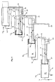
- Fig. 2 is a diagrammatical cross section view of a hydraulic jack, showing in detail the device of the invention;
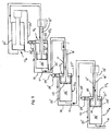
- Fig. 3 is a diagrammatical view showing the extension sequence of the sections of the crane boom of Fig. 1, as performed by the device of the invention;
- Fig. 4 is a diagrammatical view similar to Fig. 3 and showing the collapse sequence of the sections of the boom of Fig. 1; and
- Fig. 5 is a diagrammatical view similar to Fig. 4 and showing a different arrangement of the circuit branch through which the fluid is supplied during the collapse step, according to an alternative embodiment of the invention.
- With reference to the drawings, a known
hydraulic crane 1 comprises abase 2 for mounting the crane on a truck, a lorry or the like and an upright 3 supported onbase 2 and carrying afirst boom 5 hinged to it by means of a pin 4 and driven by ajack 6. Asecond boom 7, provided with slidable sections, is hinged to boom 5 and is driven by a jack 8. In a way known per se,boom 7 consists of a plurality oftelescopic sections action jacks - The device according to the invention is designed to control the sequential extension of the jacks, starting from the
first jack 13a, and the sequential collapse of the jacks starting from thelast jack 13d. To this purpose, as shown diagrammatically in Fig. 2, eachjack 13 compriseshydraulic circuit branches transfer conduits former conduits 16 being associated with the extension of the boom and thelatter conduits 17 being associated with the collapse of the boom, as will be explained below. - According to the invention,
transfer conduits rods 18 ofjacks 13.Transfer conduit 16 is intercepted by atransfer valve 19 arranged on the head ofcorresponding piston 20 ofjack 13 and mechanically operated by operatingtappets 21 engaged by thebottom 22 ofcylinder 23 of the jack. - Supplying pressurized fluid through
transfer conduit 17 will cause withdrawal of the pistons in the upstream jacks (with reference to the fluid flow) and initial collapse of the associated jack through anofftake 17a, also bored withinrod 18 and controlled by a two-ways switch 24 that is carried on saidrod 18 and is mechanically operated by acontrol finger 25 attached to the external end ofrod 18 of adjacent jack 13 (Fig. 3). One way ofswitch 24 includes a single-actingvalve 28, the other consists of afree port 29. - Two separated chambers are defined in each cylinder, a
first chamber 25 being delimited bypiston 20 andcylinder 23, and asecond chamber 27 byrod 18 andcylinder 23. - In order to extend
piston 20, pressurized fluid is supplied to thefirst chamber 26 throughbranch 14. At the end of the stroke,transfer valve 19 is opened by the engagement ofrods 21 withcylinder bottom 22, and pressurized fluid flows into thefirst chamber 26 of the downstream jack (with reference to the fluid flow), throughtransfer conduit 16, etc. The desired extension sequence of the jacks from the first 13a to the last 13d is therefore performed. During the sequence, the fluid is discharged fromsecond chamber 27 throughbranches 15 andtransfer conduits 17. - When, at the end of the stroke,
branch 15 is intercepted byconduit 17, the fluid inchamber 27 is drained throughofftake 17a,port 29 andconduit 17, which is aligned withbranch 15. - However, should
downstream jack 13b accidentally extends beforepiston 20 ofupstream jack 13a has completed its stroke (although, in this case,finger 25 switches switch 24 to causevalve 28, rather thanport 29 to interceptbranch 17a), the fluid can be drained throughofftake 17a, single-actingvalve 28 andconduit 17, thus preventing overpressures to build up in the chamber. - In order to withdraw
piston 20, pressurized fluid is supplied intosecond chamber 27 throughbranch 15. At the end of the stroke,finger 25 of the adjacent downstream jack (with reference to the fluid flow),e.g. jack 13c,switches switch 24 ofdownstream jack 13b. Consequently, single-acting valve 28 (which prevents pressurized fluid being supplied intochamber 27,e.g. jack 13a of Fig. 4) is cut off fromofftake 17a, while offtake 17a andconduit 17 are reciprocally connected throughport 29. - With reference now to Fig. 4, it can be seen that the collapse sequence starts from
last jack 13d, which, at the completion of its withdrawal stroke, switches switch 24 ofdownstream jack 13c by means of itsfinger 25. Therefore,offtake 17a is directly connected totransfer conduit 17, and pressurized fluid is supplied intochamber 27 ofjack 13c, which starts its withdrawal stroke. After a certain portion of the stroke, pressurized fluid is no longer supplied tochamber 27 throughconduit 17,valve 24 and offtake 17a, because, during the withdrawal ofpiston 20, the fluid flows directly intochamber 27 throughbranch 15. At the end of the withdrawal stroke,finger 25 ofjack 13c switches switch 24 ofdownstream jack 13b, which will starts its withdrawal, etc. During the withdrawal sequence described above, the jack located downstream of the one which is withdrawing, e.g.first jack 13a, does not move. In fact, until itsswitch 24 is switched byfinger 25 of the upstream jack, the fluid cannot be supplied intochamber 27 becauseofftake 17a is intercepted by single-actingvalve 28. - According to the alternative embodiment of Fig. 5, where similar parts bear the same reference numbers with an apex,
offtakes 17a ofwithdrawal transfer conduits 17 are dispensed with, and second hydraulic chambers 27' comprise aterminal web 30, which separates a terminal transfer portion 27t of the chamber. Moreover,switches 24 are replaced by taps 24' connectingbranches 15 to chambers 27'. All taps 24' but the penultimate are operated by fingers 25' supported by jack cylinders 23'. Single-acting valves 28', whose function will be specified below, are arranged in parallel to taps 24'. - In this alternative embodiment, the same sequence of the preferred embodiment is executed. The withdrawal sequence starts from
last jack 13d which, at the end of its withdrawal stroke, closes tap 24' ofthird jack 13c by means of itsauxiliary finger 25" which is attached to rod 18' rather than to cylinder 23', so that the pressurized fluid will flow frombranch 15 into chamber 27' of thethird jack 13c, causing the latter to start its withdrawal stroke. During this operative step, thefirst jack 13a and thesecond jack 13b cannot withdraw because their respective taps 24' are open, and the pressurized fluid cannot reach their hydraulic chambers 27' because it is directly supplied into chamber 27' ofthird jack 13c, throughbranches 15 and transfer conduits 17' of said first and second jacks. When finger 25' of thefourth jack 13d, which is supported by the rod of the third jack, closes tap 24' of thesecond jack 13b, the latter starts its withdrawal. Similarly, when control finger 25' borne bythird jack 13d closes tap 24' of thefirst jack 13a, the latter starts its withdrawal. By means of single-acting valves 28', during the jack extension the fluid can be drained from chamber 27' of the corresponding jack intobranch 15 even if the downstream jack accidentally begins to extend before the previous one has completed its extension stroke. It can in fact be seen that, in this case, the downstream jack allows the tap of the upstream jack to open, so that, due to the absence of any valves, the fluid would not be drained from chamber 27' of the upstream jack and would cause an overpressure. - Obviously, the details and the embodiments, within the concepts of the invention, can be changed extensively from what has been described and illustrated by way of non limitative example, without thereby going beyond the scope of the invention.
Claims (8)
- A device for driving the sequential extension and withdrawal of sections of telescopic booms in hydraulic cranes, the sections being driven by respective double-action, hydraulic jacks (13a-d) each having a piston (20) and a rod (18) slidable within a cylinder (23), the device comprising hydraulic circuit branches (14-15) through which hydraulic fluid is supplied to the jacks, characterized in that said branches (14-15) comprise respective extension transfer conduits (16) and withdrawal transfer conduits (17) bored inside the rods (18) of the jacks, and in that said extension transfer conduits (16) are intercepted by respective valves (19) located on the head of the respective pistons (20) of the jacks (13) and mechanically driven by engagement of control tappets (21) with the respective cylinder bottom (22), and said withdrawal transfer conduits (17) are provided with respective draining means (17a, 24, 28; 24', 28') operated by respective fingers (25, 25") borne by the piston rod (18) of the adjacent upstream jack.
- The device of claim 1, characterized in that said draining means comprise respective offtakes (17a) from the withdrawal transfer conduits (17), controlled by respective switches (24) which are mechanically operated by said fingers (25).
- The device of claim 1 or 2, characterized in that said switch (24) is a two-way switch in which one of the ways includes a single-acting valve (28), and the other way consists of a free port (29).
- The device of claim 3, characterized in that the hydraulic fluid is dischargeable, at the end of the extending stroke of the corresponding piston (20), from the residual portion of said second chamber (27) through said single-acting valve (28) of the switch (24).
- The device of claim 4, characterized in that said single-acting valve (28) intercepts also, during the withdrawal step, the offtake (17a) of the corresponding jack, preventing pressurized fluid to be supplied into the second hydraulic chamber (27) until the upstream jack, at the end of its contracting stroke, switches the switch by its finger (25) and cuts off the single-acting valve (28) of said offtake (17a).
- The device of claim 6, characterized in that said switches (24) are supported by, and integral to, the end of the rods (18) of each jack (13).
- The device of claim 1, characterized in that each cylinder (23) is provided with a web (30) delimiting a terminal chamber (27t) near the rod end of the cylinder and in that said draining means comprise respective, normally closed taps (24') connecting said terminal chambers (27t) with the main cylinders and mechanically operated, except the last, by said fingers (25').
- The device of claim 7, characterized in that said taps (24') are provided with single-acting valves (28'), arranged in parallel to the taps (24') and connecting the second chambers (27') to the branch (15), whereby the fluid can be drained even if the downstream jack begins to extend before the previous one has completed its extension stroke.
Applications Claiming Priority (2)
| Application Number | Priority Date | Filing Date | Title |
|---|---|---|---|
| ITTO20010586 ITTO20010586A1 (en) | 2001-06-18 | 2001-06-18 | PERFECTED DEVICE FOR DISPLACEMENT AND SEQUENTIAL RETURN OF SECTIONS OF TELESCOPIC ARMS OF HYDRAULIC CRANES. |
| ITTO20010586 | 2001-06-18 |
Publications (1)
| Publication Number | Publication Date |
|---|---|
| EP1270494A1 true EP1270494A1 (en) | 2003-01-02 |
Family
ID=11458970
Family Applications (1)
| Application Number | Title | Priority Date | Filing Date |
|---|---|---|---|
| EP02013063A Withdrawn EP1270494A1 (en) | 2001-06-18 | 2002-06-13 | Extension device for telescopic booms of hydraulic cranes |
Country Status (2)
| Country | Link |
|---|---|
| EP (1) | EP1270494A1 (en) |
| IT (1) | ITTO20010586A1 (en) |
Cited By (12)
| Publication number | Priority date | Publication date | Assignee | Title |
|---|---|---|---|---|
| WO2012119169A1 (en) * | 2011-03-10 | 2012-09-13 | Palfinger Ag | Loading crane jib |
| EP2101066A3 (en) * | 2008-03-12 | 2013-02-20 | Linde Material Handling GmbH | Device for sequentially moving at least two fluid-actuated displacement devices |
| CN103899585A (en) * | 2014-03-03 | 2014-07-02 | 徐州徐工随车起重机有限公司 | Hydraulic control system with two oil cylinders performing orderly telescopic motion, suspension arm mechanism and crane |
| WO2015086532A1 (en) * | 2013-12-12 | 2015-06-18 | Fella Werke Gmbh | Hydraulic system for automatic sequential cylinder operation |
| CN105370645A (en) * | 2015-12-14 | 2016-03-02 | 黑龙江省农业机械工程科学研究院 | Novel sequential action hydraulic cylinder |
| CN105605022A (en) * | 2016-03-14 | 2016-05-25 | 三一帕尔菲格特种车辆装备有限公司 | Multi-oil-cylinder sequential telescopic mechanism and engineering machine |
| CN105864134A (en) * | 2016-04-22 | 2016-08-17 | 三帕尔菲格特种车辆装备有限公司 | Multi-oil-cylinder sequential telescopic system and crane |
| CN109973463A (en) * | 2019-04-22 | 2019-07-05 | 韶关市起重机厂有限责任公司 | A kind of oil cylinder, Multi-cylinder sequential telescopic mechanism and engineering machinery that energy reliable sequence is flexible |
| CN112797042A (en) * | 2021-02-02 | 2021-05-14 | 柳州柳工液压件有限公司 | Integrated main control valve, hydraulic system and crane |
| RU205844U1 (en) * | 2021-04-28 | 2021-08-11 | Открытое акционерное общество "Машиностроительный завод "АРСЕНАЛ" | HYDRAULICALLY OPERATED TELESCOPIC SHIP CRANE BOOM |
| RU2771616C1 (en) * | 2021-04-28 | 2022-05-12 | Открытое акционерное общество "Машиностроительный завод "АРСЕНАЛ" | Hydraulically controlled telescopic jib of a ship crane |
| CN120667438A (en) * | 2025-08-05 | 2025-09-19 | 韶关市起重机厂有限责任公司 | Sequential telescopic oil cylinder and control valve thereof |
Citations (3)
| Publication number | Priority date | Publication date | Assignee | Title |
|---|---|---|---|---|
| IT1233225B (en) * | 1989-07-21 | 1992-03-20 | Fassi Gru Idrauliche S P A | SEQUENTIAL REMOVAL AND RETURN DEVICE OF CONTROLLED SECTION OF TELESCOPIC ARMS FOR HYDRAULIC CRANES |
| US5518129A (en) * | 1991-10-21 | 1996-05-21 | Palfinger Aktiengesellschaft | Boom including plural arms telescopically extendible and retractable successively |
| WO1996041764A1 (en) * | 1995-06-08 | 1996-12-27 | Hiab Ab | Extendible boom, particularly for cranes |
-
2001
- 2001-06-18 IT ITTO20010586 patent/ITTO20010586A1/en unknown
-
2002
- 2002-06-13 EP EP02013063A patent/EP1270494A1/en not_active Withdrawn
Patent Citations (3)
| Publication number | Priority date | Publication date | Assignee | Title |
|---|---|---|---|---|
| IT1233225B (en) * | 1989-07-21 | 1992-03-20 | Fassi Gru Idrauliche S P A | SEQUENTIAL REMOVAL AND RETURN DEVICE OF CONTROLLED SECTION OF TELESCOPIC ARMS FOR HYDRAULIC CRANES |
| US5518129A (en) * | 1991-10-21 | 1996-05-21 | Palfinger Aktiengesellschaft | Boom including plural arms telescopically extendible and retractable successively |
| WO1996041764A1 (en) * | 1995-06-08 | 1996-12-27 | Hiab Ab | Extendible boom, particularly for cranes |
Cited By (21)
| Publication number | Priority date | Publication date | Assignee | Title |
|---|---|---|---|---|
| EP2101066A3 (en) * | 2008-03-12 | 2013-02-20 | Linde Material Handling GmbH | Device for sequentially moving at least two fluid-actuated displacement devices |
| WO2012119169A1 (en) * | 2011-03-10 | 2012-09-13 | Palfinger Ag | Loading crane jib |
| AT12645U1 (en) * | 2011-03-10 | 2012-09-15 | Palfinger Ag | CRANE BOOM |
| CN103429522A (en) * | 2011-03-10 | 2013-12-04 | 帕尔菲格股份有限公司 | Loading crane jib |
| US9718655B2 (en) | 2011-03-10 | 2017-08-01 | Palfinger Ag | Loading crane jib |
| CN103429522B (en) * | 2011-03-10 | 2015-10-21 | 帕尔菲格股份有限公司 | Stevedoring crane cantilever |
| AU2012225180B2 (en) * | 2011-03-10 | 2017-05-18 | Palfinger Ag | Loading crane jib |
| RU2610898C2 (en) * | 2011-03-10 | 2017-02-17 | Палфингер Аг | Loading crane boom |
| WO2015086532A1 (en) * | 2013-12-12 | 2015-06-18 | Fella Werke Gmbh | Hydraulic system for automatic sequential cylinder operation |
| CN103899585B (en) * | 2014-03-03 | 2016-08-24 | 徐州徐工随车起重机有限公司 | The hydraulic control system of a kind of pair of oil cylinder sequential telescopic, suspension arm mechanism and crane |
| CN103899585A (en) * | 2014-03-03 | 2014-07-02 | 徐州徐工随车起重机有限公司 | Hydraulic control system with two oil cylinders performing orderly telescopic motion, suspension arm mechanism and crane |
| CN105370645B (en) * | 2015-12-14 | 2017-04-19 | 黑龙江省农业机械工程科学研究院 | Novel sequential action hydraulic cylinder |
| CN105370645A (en) * | 2015-12-14 | 2016-03-02 | 黑龙江省农业机械工程科学研究院 | Novel sequential action hydraulic cylinder |
| CN105605022A (en) * | 2016-03-14 | 2016-05-25 | 三一帕尔菲格特种车辆装备有限公司 | Multi-oil-cylinder sequential telescopic mechanism and engineering machine |
| CN105605022B (en) * | 2016-03-14 | 2018-06-12 | 三一帕尔菲格特种车辆装备有限公司 | A kind of Multi-cylinder sequential telescopic mechanism and engineering machinery |
| CN105864134A (en) * | 2016-04-22 | 2016-08-17 | 三帕尔菲格特种车辆装备有限公司 | Multi-oil-cylinder sequential telescopic system and crane |
| CN109973463A (en) * | 2019-04-22 | 2019-07-05 | 韶关市起重机厂有限责任公司 | A kind of oil cylinder, Multi-cylinder sequential telescopic mechanism and engineering machinery that energy reliable sequence is flexible |
| CN112797042A (en) * | 2021-02-02 | 2021-05-14 | 柳州柳工液压件有限公司 | Integrated main control valve, hydraulic system and crane |
| RU205844U1 (en) * | 2021-04-28 | 2021-08-11 | Открытое акционерное общество "Машиностроительный завод "АРСЕНАЛ" | HYDRAULICALLY OPERATED TELESCOPIC SHIP CRANE BOOM |
| RU2771616C1 (en) * | 2021-04-28 | 2022-05-12 | Открытое акционерное общество "Машиностроительный завод "АРСЕНАЛ" | Hydraulically controlled telescopic jib of a ship crane |
| CN120667438A (en) * | 2025-08-05 | 2025-09-19 | 韶关市起重机厂有限责任公司 | Sequential telescopic oil cylinder and control valve thereof |
Also Published As
| Publication number | Publication date |
|---|---|
| ITTO20010586A1 (en) | 2002-12-18 |
Similar Documents
| Publication | Publication Date | Title |
|---|---|---|
| US5584645A (en) | Telescopic boom with a multistage, lockable hydraulic cylinder protected against buckling | |
| EP3199485B1 (en) | A telescopic arm for self-propelled operating machines | |
| EP1270494A1 (en) | Extension device for telescopic booms of hydraulic cranes | |
| US20190084816A1 (en) | Industrial truck, hydraulic system for an industrial truck and method for operating a hydraulic system | |
| KR19990082971A (en) | Telescoping system with multi-stage telescopic cylinder | |
| US3483798A (en) | Telescopic hydraulic actuator | |
| US3481489A (en) | Means for extending and retracting boom sections of a crane | |
| JP5882977B2 (en) | Crane boom telescopic device | |
| EP1707529B1 (en) | Multistaged telescopic boom | |
| US7703616B2 (en) | Telescopable sliding beam | |
| US5518129A (en) | Boom including plural arms telescopically extendible and retractable successively | |
| JP2002070809A (en) | Double acting multi-stage cylinder | |
| JP4122903B2 (en) | crane | |
| GB2068330A (en) | Telescopic crane jib | |
| GB2206929A (en) | Improvements in or relating to hydraulically operated telescopic devices | |
| CN113614018A (en) | Telescopic device and crane | |
| JP7416281B2 (en) | work equipment | |
| JP3126657B2 (en) | Boom telescopic device | |
| JP5048260B2 (en) | Telescopic boom telescopic mechanism | |
| US20260097944A1 (en) | Method for operating a hydraulic system of an industrial truck having a plurality of hydraulic pumps, and industrial truck | |
| SU1736909A1 (en) | Lifting machine extendable support | |
| JP7756585B2 (en) | Ladder/boom equipped vehicle | |
| KR101726843B1 (en) | Working Fluid Filling Apparatus for preventing nature descent | |
| EP0310022B1 (en) | Hydraulic telescopic device | |
| US3064581A (en) | Reciprocating hydraulic pumps |
Legal Events
| Date | Code | Title | Description |
|---|---|---|---|
| PUAI | Public reference made under article 153(3) epc to a published international application that has entered the european phase |
Free format text: ORIGINAL CODE: 0009012 |
|
| AK | Designated contracting states |
Kind code of ref document: A1 Designated state(s): AT BE CH CY DE DK ES FI FR GB GR IE IT LI LU MC NL PT SE TR |
|
| AX | Request for extension of the european patent |
Free format text: AL;LT;LV;MK;RO;SI |
|
| 17P | Request for examination filed |
Effective date: 20030405 |
|
| 17Q | First examination report despatched |
Effective date: 20030606 |
|
| AKX | Designation fees paid |
Designated state(s): AT BE CH CY DE DK ES FI FR GB GR IE IT LI LU MC NL PT SE TR |
|
| GRAP | Despatch of communication of intention to grant a patent |
Free format text: ORIGINAL CODE: EPIDOSNIGR1 |
|
| STAA | Information on the status of an ep patent application or granted ep patent |
Free format text: STATUS: THE APPLICATION IS DEEMED TO BE WITHDRAWN |
|
| 18D | Application deemed to be withdrawn |
Effective date: 20050627 |