EP1273869A2 - Gepanzertes Fahrzeug - Google Patents
Gepanzertes Fahrzeug Download PDFInfo
- Publication number
- EP1273869A2 EP1273869A2 EP02010800A EP02010800A EP1273869A2 EP 1273869 A2 EP1273869 A2 EP 1273869A2 EP 02010800 A EP02010800 A EP 02010800A EP 02010800 A EP02010800 A EP 02010800A EP 1273869 A2 EP1273869 A2 EP 1273869A2
- Authority
- EP
- European Patent Office
- Prior art keywords
- vehicle
- weapon
- mortar
- ammunition
- magazines
- Prior art date
- Legal status (The legal status is an assumption and is not a legal conclusion. Google has not performed a legal analysis and makes no representation as to the accuracy of the status listed.)
- Granted
Links
- 239000004570 mortar (masonry) Substances 0.000 claims abstract description 26
- 238000010304 firing Methods 0.000 claims abstract description 8
- 239000003380 propellant Substances 0.000 claims description 2
- 230000033001 locomotion Effects 0.000 claims 1
- 229940125585 NDV-HXP-S Drugs 0.000 description 1
- 238000005474 detonation Methods 0.000 description 1
- 230000000694 effects Effects 0.000 description 1
- 238000009434 installation Methods 0.000 description 1
- 230000010354 integration Effects 0.000 description 1
Images


Classifications
-
- F—MECHANICAL ENGINEERING; LIGHTING; HEATING; WEAPONS; BLASTING
- F41—WEAPONS
- F41A—FUNCTIONAL FEATURES OR DETAILS COMMON TO BOTH SMALLARMS AND ORDNANCE, e.g. CANNONS; MOUNTINGS FOR SMALLARMS OR ORDNANCE
- F41A23/00—Gun mountings, e.g. on vehicles; Disposition of guns on vehicles
- F41A23/34—Gun mountings, e.g. on vehicles; Disposition of guns on vehicles on wheeled or endless-track vehicles
-
- F—MECHANICAL ENGINEERING; LIGHTING; HEATING; WEAPONS; BLASTING
- F41—WEAPONS
- F41A—FUNCTIONAL FEATURES OR DETAILS COMMON TO BOTH SMALLARMS AND ORDNANCE, e.g. CANNONS; MOUNTINGS FOR SMALLARMS OR ORDNANCE
- F41A9/00—Feeding or loading of ammunition; Magazines; Guiding means for the extracting of cartridges
- F41A9/38—Loading arrangements, i.e. for bringing the ammunition into the firing position
- F41A9/45—Loading arrangements, i.e. for bringing the ammunition into the firing position the cartridge chamber or the barrel as a whole being tiltable or transversely slidable between a loading and a firing position
Definitions
- the invention relates to an armored vehicle according to the The preamble of claim 1 features specified.
- Such a vehicle consists of the usual parts such as Drive motor, gears, wheelsets or chain drive, one Crew room and a housing that contains all fittings and attachments takes up together.
- a rifle combat vehicle several soldiers are transported by vehicle, who quickly over get out of the rear exit and sit on it.
- Another one Vehicle type, the armored transport vehicle, abbreviated GTK the vehicle is divided into modules and a so-called Mission module interchangeably housed on the chassis. Different armaments and equipment can then be used as a module can be carried interchangeably on the vehicle.
- AMOS Advanced Mortar System
- the rear-loading mortar weapon as a turret solution is a larger one Integration effort compared to a muzzle-loading mortar weapon required.
- the other known solution (Bofors) with double-tube front loader has one Gun cradle as storage for both gun barrels, so that none There is redundancy in the directional drive and the pipes are not independent can be directed from each other.
- the double system is also Realized in the center of the rear of the vehicle, so that a rear exit is given Dimensions is not feasible.
- the object of the invention is two mortar weapons, preferably 120 mm to integrate redundantly in a known vehicle.
- the Rear exit of the vehicle is not affected, muzzle-loading mortar are used and the entire operation of the mortar weapons under armor protection for the crew.
- the invention is based on the knowledge that the rear of the vehicle or at the rear end of the mission module, which is on the vehicle a pivot is installed on both sides left and right at the rear stored preferably 120mm mortar weapon with a respective one Return device are attached.
- Both mortar weapons have one each Straightening system that coordinates and via a control and computer system is controlled so that, for example, both weapons the same target can fight. If necessary, the weapons can also be aimed in this way be that a simultaneous detonation in the target area with one after the other and grenades fired in parallel, with which the Fire effect is increased significantly. For this mode of operation multiple ammunition for each weapon in an associated automated Magazine held.
- the advantages of the invention lie in the higher firepower with two Weapons compared to a weapon on the vehicle and the redundancy of the 2-weapon version, because even if a weapon fails, the fighting power preserved.
- By attaching to the rear using pivot storage there are only minor changes in the attachment of the weapon to one Base vehicle required. Above all, the rear exit can remain unchanged for the crew (7,8) or other functions, because the weapons are attached to the left and right of the rear exit.
- every single weapon is available and not for the existing purpose must be converted or developed.
- the muzzle-loading principle of the mortar means there is no shot gas load for the Operator and crew as opposed to using a mortar weapon with lock and rear loading. Through the automated ammunition flow an automated magazine increases the firing order reached which is higher than that with manual operation. Additional advantages result from the subclaims.
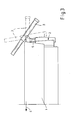
- FIGs 1 to 4 show the attachment of two 120mm mortar weapon systems (3) at the rear (2) of a mission module or at the rear of the Vehicle (1).
- the vehicle moves forward in the direction of travel (4).
- By attaching the weapons (3) to the rear the rear exit (5) is guaranteed.
- each Wafer system (3) is by means of a side-directional pivot (6) at the rear (2) of the vehicle.
- the weapon is loaded in the index position with 0 ° side and 0 ° height. Before each shot, the weapon is put in one Firing position aimed. After the shooting is back in the Loading position directed, the gun barrel (3a) in the loading trough (15) is pivoted in the vehicle roof.
- the weapon is loaded by the Loading flap (14) ( Figure 7) in the pipe mouth after the Muzzle-loading principle.
- the mortar tube is at different heights directed.
- the right tube is from the side Index position directed out.
- the magazine (11) is regarding the vehicle center and longitudinal axis positioned so that the seating position the loader (7) ergonomic operation of the magazine (11) allowed.
- the second right magazine (10) with an associated Loaders (8) under the same conditions as the left one Illustrated magazine.
- a through-loading tube (13) pushing the ammunition through a loading flap (14) into the Gun barrel (3a).
- the ammunition is directly through a corresponding loading flap (14) pushed into the gun barrel (3a).
- the arrangement of the two magazines is also possible interchanged depending on Space required for further installations.
- the arrangement and size of the two magazines (10, 11) including loaders is related to that Vehicle housing chosen so that a passage to the rear through the Rear exit (2) and vice versa is ensured.
- the storage of the The easiest way to do ammunition, for example, is horizontally in relation to yours Main direction in electrically driven belt magazines.
- piecing (16) used which are designed, for example, as chain attachers.
Landscapes
- Engineering & Computer Science (AREA)
- General Engineering & Computer Science (AREA)
- Aiming, Guidance, Guns With A Light Source, Armor, Camouflage, And Targets (AREA)
- Control Of Vehicles With Linear Motors And Vehicles That Are Magnetically Levitated (AREA)
- Fittings On The Vehicle Exterior For Carrying Loads, And Devices For Holding Or Mounting Articles (AREA)
- Body Structure For Vehicles (AREA)
- Refuge Islands, Traffic Blockers, Or Guard Fence (AREA)
Abstract
Description
- Figur 1:
- Eine Teil-Draufsicht im Schnitt des Fahrzeuges mit Waffenanlage
- Figur 2:
- die Ansicht der Figur 1 in einer Perspektive
- Figur 3:
- eine Seitenansicht des Fahrzeugs gemäß Figur 1
- Figur 4:
- eine rückwärtige Ansicht des Fahrzeugs gemäß Figur 1
- Figur 5:
- einen Fahrzeug-Querschnitt mit Detail Ladeschütze und Magazin links
- Figur 6:
- einen Fahrzeug-Querschnitt mit Ladeschütze und Magazin rechts
- Figur 7:
- eine Teil-Draufsicht des Fahrzeuges im Schnitt mit Ladeschützen links und rechts
- 1
- Fahrzeug
- 2
- Heck
- 3
- Mörser-Waffenanlage
- 3a
- Waffenrohr
- 4
- Fahrtrichtung
- 5
- Heckausstieg
- 6
- Pivot
- 7
- Ladeschütze
- 8
- Ladeschütze
- 9
- Munition
- 10
- Magazin
- 11
- Magazin
- 12
- weiteres Magazin
- 13
- Durchladerohr
- 14
- Ladeklappe
- 15
- Lademulde
- 16
- Ansetzer
Claims (9)
- Gepanzertes Fahrzeug (1) mit einem Radfahr- oder Kettenlaufwerk und einem Antrieb zur Fortbewegung sowie einem Fahrzeugaufbau zur Aufnahme und Einbau aller Komponenten für den Betrieb des Fahrzeugs (1) einschließlich einer Fahrzeugbesatzung (7,8) und einem Heckausstieg (5) am Heck des Fahrzeugs (1),
dadurch gekennzeichnet, dass am Heck des Fahrzeugs (1) an beiden Seiten links und rechts von dem Heckausstieg (5) jeweils eine unter Panzerschutz bedien- und ladbare Mörserwaffenanlage (3) mit Waffenrohr (3a) und Pivot-Lafette (6), Richtantrieben und Abfeuerung angeordnet ist. - Fahrzeug nach Anspruch 1,
dadurch gekennzeichnet, dass beide Mörserwaffenanlagen (3) mittels einer Steuer- und Rechnereinrichtung am Fahrzeug in ihrem Abschussverhalten eingerichtet und koordiniert werden können, zum Beispiel mit gleicher Ausrichtung der Rohre. - Fahrzeug nach Anspruch 1 und 2,
dadurch gekennzeichnet, dass für jede Mörserwaffe (3) ein automatisiertes Magazin (10,11) mit Vorhaltung von mehreren Munitionen (9) eingebaut ist. - Fahrzeug nach Anspruch 3,
dadurch gekennzeichnet, dass mindestens eines der zwei automatisierten Magazine (10,11) die manuelle Einstellung der darin untergebrachten Munitionen (9), zum Beispiel eine Treibladungseinstellung, ermöglicht. - Fahrzeug nach einem der Ansprüche 1- 4,
dadurch gekennzeichnet, dass die beiden Mörserwaffen (3) eine gemeinsame oder jeweils eine getrennte Waffenrichtanlage haben oder eine Kombination aus beiden. - Fahrzeug nach einem der Ansprüche 1 - 5,
dadurch gekennzeichnet, dass die Magazine (10,11) so angeordnet sind, dass ein Durchgang durch den Heckausstieg (5) und die manuelle Einstellung der Munition (9) durch Ladeschützen (7,8) möglich ist. - Fahrzeug nach einem der Ansprüche 1 - 6,
dadurch gekennzeichnet, dass für die Anordnung der Magazine (10,11) im Fahrzeug (1) ein Durchladerohr (13) eingebaut ist. - Fahrzeug nach einem der'Ansprüche 1 - 7,
dadurch gekennzeichnet, dass die zur Anwendung kommenden Magazine (10,11) als elektrisch angetriebene Bandmagazine ausgeführt sind. - Vorrichtung nach einem der Ansprüche 1 - 8,
dadurch gekennzeichnet, dass das Hineinschieben der Munition in das jeweilige Waffenrohr mittels Kettenansetzer (16) erfolgt.
Applications Claiming Priority (2)
| Application Number | Priority Date | Filing Date | Title |
|---|---|---|---|
| DE10133144A DE10133144A1 (de) | 2001-07-07 | 2001-07-07 | Gepanzertes Fahrzeug |
| DE10133144 | 2001-07-07 |
Publications (3)
| Publication Number | Publication Date |
|---|---|
| EP1273869A2 true EP1273869A2 (de) | 2003-01-08 |
| EP1273869A3 EP1273869A3 (de) | 2004-06-09 |
| EP1273869B1 EP1273869B1 (de) | 2008-02-20 |
Family
ID=7691068
Family Applications (1)
| Application Number | Title | Priority Date | Filing Date |
|---|---|---|---|
| EP02010800A Expired - Lifetime EP1273869B1 (de) | 2001-07-07 | 2002-05-15 | Gepanzertes Fahrzeug |
Country Status (5)
| Country | Link |
|---|---|
| EP (1) | EP1273869B1 (de) |
| AT (1) | ATE386918T1 (de) |
| DE (2) | DE10133144A1 (de) |
| DK (1) | DK1273869T3 (de) |
| ES (1) | ES2301586T3 (de) |
Cited By (1)
| Publication number | Priority date | Publication date | Assignee | Title |
|---|---|---|---|---|
| FR3002030A1 (fr) * | 2013-02-12 | 2014-08-15 | Nexter Systems | Systeme d'arme leger |
Families Citing this family (2)
| Publication number | Priority date | Publication date | Assignee | Title |
|---|---|---|---|---|
| DE10204299B4 (de) * | 2002-02-02 | 2004-03-11 | Rheinmetall Landsysteme Gmbh | Zwangsgeführter Entnahmemechanismus für Waffen, Geräte oder Besatzungs-Ausrüstung in einem gepanzerten Transportfahrzeug |
| DE102012001172A1 (de) * | 2012-01-24 | 2013-07-25 | Rheinmetall Waffe Munition Gmbh | Waffe, wie Mörser oder Düsenmörser, mit Lafette |
Citations (1)
| Publication number | Priority date | Publication date | Assignee | Title |
|---|---|---|---|---|
| DE19927646C1 (de) | 1999-06-17 | 2001-03-01 | Wieland Werke Ag | Verwendung einer zinnreichen Kupfer-Zinn-Eisen-Legierung |
Family Cites Families (12)
| Publication number | Priority date | Publication date | Assignee | Title |
|---|---|---|---|---|
| FR1099576A (fr) * | 1954-02-16 | 1955-09-07 | Véhicule blindé de combat | |
| FR1602851A (de) * | 1954-03-16 | 1971-02-08 | ||
| DE2043852A1 (de) * | 1969-09-04 | 1971-03-11 | Societe Nationale Industrielle Aerospatiale Paris | Versenkbare Abschußvorrichtung fur Lenkwaffen |
| FR2301797A1 (fr) * | 1975-02-18 | 1976-09-17 | Creusot Loire | Installation de lancement de missiles |
| US4326446A (en) * | 1979-11-19 | 1982-04-27 | The United States Of America As Represented By The Secretary Of The Army | Linkage of actuating system for elevating gun mount |
| DE3121963A1 (de) * | 1981-06-03 | 1982-12-23 | Rheinmetall GmbH, 4000 Düsseldorf | Moerser mit einer in eine rohrwiege integrierten ruecklauf-vorholeinrichtung |
| DE3440467A1 (de) * | 1984-11-06 | 1986-05-07 | Diehl GmbH & Co, 8500 Nürnberg | Waffensystem mit rohrwaffe im panzerfahrzeug |
| DE3703952A1 (de) * | 1987-02-10 | 1988-08-18 | Krupp Gmbh | Bedien- und ueberwachungskonsole fuer einen panzer |
| AT408690B (de) * | 1996-06-20 | 2002-02-25 | Dynamit Nobel Graz Gmbh | Steilfeuergeschütz, insbesondere granatwerfer |
| ES2140171T3 (es) * | 1996-08-20 | 2000-02-16 | Kraus Maffei Wegmann Gmbh & Co | Vehiculo de combate con accionamiento diesel-electrico y con puerta trasera. |
| DE19633904C2 (de) * | 1996-08-22 | 2000-01-20 | Rheinmetall W & M Gmbh | Vorderladerwaffe |
| DE19713192C2 (de) * | 1997-03-27 | 2000-02-24 | Rheinmetall Ind Ag | Trägerfahrzeug für eine Rohrwaffe mit einer Abstützvorrichtung |
-
2001
- 2001-07-07 DE DE10133144A patent/DE10133144A1/de not_active Withdrawn
-
2002
- 2002-05-15 EP EP02010800A patent/EP1273869B1/de not_active Expired - Lifetime
- 2002-05-15 ES ES02010800T patent/ES2301586T3/es not_active Expired - Lifetime
- 2002-05-15 DK DK02010800T patent/DK1273869T3/da active
- 2002-05-15 DE DE50211720T patent/DE50211720D1/de not_active Expired - Lifetime
- 2002-05-15 AT AT02010800T patent/ATE386918T1/de active
Patent Citations (1)
| Publication number | Priority date | Publication date | Assignee | Title |
|---|---|---|---|---|
| DE19927646C1 (de) | 1999-06-17 | 2001-03-01 | Wieland Werke Ag | Verwendung einer zinnreichen Kupfer-Zinn-Eisen-Legierung |
Cited By (3)
| Publication number | Priority date | Publication date | Assignee | Title |
|---|---|---|---|---|
| FR3002030A1 (fr) * | 2013-02-12 | 2014-08-15 | Nexter Systems | Systeme d'arme leger |
| WO2014125195A1 (fr) | 2013-02-12 | 2014-08-21 | Nexter Systems | Systeme d'arme leger |
| EP2956738B1 (de) | 2013-02-12 | 2017-04-19 | NEXTER Systems | Leichtes waffensystem |
Also Published As
| Publication number | Publication date |
|---|---|
| DK1273869T3 (da) | 2008-06-02 |
| DE10133144A1 (de) | 2003-01-30 |
| ES2301586T3 (es) | 2008-07-01 |
| EP1273869A3 (de) | 2004-06-09 |
| EP1273869B1 (de) | 2008-02-20 |
| ATE386918T1 (de) | 2008-03-15 |
| DE50211720D1 (de) | 2008-04-03 |
Similar Documents
| Publication | Publication Date | Title |
|---|---|---|
| EP1061323B1 (de) | Gepanzertes Transportkraftfahrzeug | |
| DE102007041294B4 (de) | Munitionsbevorratung | |
| DE60210182T2 (de) | Mit zwei Waffen versehener Turm für ein militärisches Kampffahrzeug | |
| EP0141900B1 (de) | Ladeautomat für ein Panzerfahrzeug mit drehbarem Panzerturm | |
| DE10258263B4 (de) | Schießmodul | |
| DE3719289C1 (en) | Small combat vehicle system, configured in a modular manner, for wheeled or tracked vehicles (track-laying vehicles | |
| EP1717541B1 (de) | Wurfanlage | |
| EP0042166B1 (de) | Panzerfahrzeug mit auswechselbarem Munitionsmagazin | |
| DE69005089T2 (de) | Turm für Leichtpanzer, ausgerüstet mit einer seitlich angebrachten Waffe. | |
| DE19717734A1 (de) | Kampffahrzeug | |
| EP2710323B1 (de) | Geschütz und militärisches fahrzeug | |
| EP0844455B1 (de) | Anordnung eines Geschützes in einem Panzerturm | |
| EP1273869A2 (de) | Gepanzertes Fahrzeug | |
| DE19644524C2 (de) | Geschützturm für Panzerfahrzeuge | |
| DE3042675A1 (de) | Waffenlade-einrichtung | |
| EP0635695B1 (de) | Kampffahrzeug, insbesondere Panzerhaubitze, mit Munitionsmagazinen | |
| DE2019144C1 (de) | Panzerfahrzeug mit niedriger Silhouette | |
| DE20122721U1 (de) | Gepanzertes Fahrzeug | |
| DE10160207B4 (de) | Munitionsmagazin | |
| DE102015008796A1 (de) | Waffe mit einem Rohrbündel | |
| US6481328B1 (en) | Method and device for handling propellant charges | |
| WO2019201518A1 (de) | Autolader sowie fahrzeug mit einem autolader | |
| DE2852699C1 (de) | Einrichtung fuer die Munitionszufuhr aus einem unterhalb einer drehbaren Plattform befindlichen Magazin zu einem auf der Plattform angeordneten scheitellafettierten Geschuetz | |
| EP1273871B1 (de) | Gepanzertes Transportfahrzeug | |
| DE102021001804A1 (de) | Panzerhaubitze im kaliber 203 mm |
Legal Events
| Date | Code | Title | Description |
|---|---|---|---|
| PUAI | Public reference made under article 153(3) epc to a published international application that has entered the european phase |
Free format text: ORIGINAL CODE: 0009012 |
|
| AK | Designated contracting states |
Kind code of ref document: A2 Designated state(s): AT BE CH CY DE DK ES FI FR GB GR IE IT LI LU MC NL PT SE TR |
|
| AX | Request for extension of the european patent |
Free format text: AL;LT;LV;MK;RO;SI |
|
| PUAL | Search report despatched |
Free format text: ORIGINAL CODE: 0009013 |
|
| AK | Designated contracting states |
Kind code of ref document: A3 Designated state(s): AT BE CH CY DE DK ES FI FR GB GR IE IT LI LU MC NL PT SE TR |
|
| AX | Request for extension of the european patent |
Extension state: AL LT LV MK RO SI |
|
| 17P | Request for examination filed |
Effective date: 20040429 |
|
| AKX | Designation fees paid |
Designated state(s): AT BE CH CY DE DK ES FI FR GB GR IE IT LI LU MC NL PT SE TR |
|
| RAP1 | Party data changed (applicant data changed or rights of an application transferred) |
Owner name: RHEINMETALL LANDSYSTEME GMBH |
|
| 17Q | First examination report despatched |
Effective date: 20061018 |
|
| GRAP | Despatch of communication of intention to grant a patent |
Free format text: ORIGINAL CODE: EPIDOSNIGR1 |
|
| GRAS | Grant fee paid |
Free format text: ORIGINAL CODE: EPIDOSNIGR3 |
|
| GRAA | (expected) grant |
Free format text: ORIGINAL CODE: 0009210 |
|
| AK | Designated contracting states |
Kind code of ref document: B1 Designated state(s): AT BE CH CY DE DK ES FI FR GB GR IE IT LI LU MC NL PT SE TR |
|
| REG | Reference to a national code |
Ref country code: GB Ref legal event code: FG4D Free format text: NOT ENGLISH |
|
| REG | Reference to a national code |
Ref country code: CH Ref legal event code: EP |
|
| REG | Reference to a national code |
Ref country code: IE Ref legal event code: FG4D Free format text: LANGUAGE OF EP DOCUMENT: GERMAN |
|
| REF | Corresponds to: |
Ref document number: 50211720 Country of ref document: DE Date of ref document: 20080403 Kind code of ref document: P |
|
| REG | Reference to a national code |
Ref country code: SE Ref legal event code: TRGR |
|
| GBT | Gb: translation of ep patent filed (gb section 77(6)(a)/1977) |
Effective date: 20080423 |
|
| REG | Reference to a national code |
Ref country code: DK Ref legal event code: T3 |
|
| REG | Reference to a national code |
Ref country code: CH Ref legal event code: NV Representative=s name: OK PAT AG PATENTE MARKEN LIZENZEN |
|
| REG | Reference to a national code |
Ref country code: ES Ref legal event code: FG2A Ref document number: 2301586 Country of ref document: ES Kind code of ref document: T3 |
|
| REG | Reference to a national code |
Ref country code: IE Ref legal event code: FD4D |
|
| ET | Fr: translation filed | ||
| PG25 | Lapsed in a contracting state [announced via postgrant information from national office to epo] |
Ref country code: IE Free format text: LAPSE BECAUSE OF FAILURE TO SUBMIT A TRANSLATION OF THE DESCRIPTION OR TO PAY THE FEE WITHIN THE PRESCRIBED TIME-LIMIT Effective date: 20080220 Ref country code: PT Free format text: LAPSE BECAUSE OF FAILURE TO SUBMIT A TRANSLATION OF THE DESCRIPTION OR TO PAY THE FEE WITHIN THE PRESCRIBED TIME-LIMIT Effective date: 20080721 |
|
| BERE | Be: lapsed |
Owner name: RHEINMETALL LANDSYSTEME G.M.B.H. Effective date: 20080531 |
|
| PLBE | No opposition filed within time limit |
Free format text: ORIGINAL CODE: 0009261 |
|
| STAA | Information on the status of an ep patent application or granted ep patent |
Free format text: STATUS: NO OPPOSITION FILED WITHIN TIME LIMIT |
|
| PG25 | Lapsed in a contracting state [announced via postgrant information from national office to epo] |
Ref country code: MC Free format text: LAPSE BECAUSE OF NON-PAYMENT OF DUE FEES Effective date: 20080531 |
|
| 26N | No opposition filed |
Effective date: 20081121 |
|
| PG25 | Lapsed in a contracting state [announced via postgrant information from national office to epo] |
Ref country code: BE Free format text: LAPSE BECAUSE OF NON-PAYMENT OF DUE FEES Effective date: 20080531 |
|
| PG25 | Lapsed in a contracting state [announced via postgrant information from national office to epo] |
Ref country code: CY Free format text: LAPSE BECAUSE OF FAILURE TO SUBMIT A TRANSLATION OF THE DESCRIPTION OR TO PAY THE FEE WITHIN THE PRESCRIBED TIME-LIMIT Effective date: 20080220 |
|
| PGFP | Annual fee paid to national office [announced via postgrant information from national office to epo] |
Ref country code: DK Payment date: 20090513 Year of fee payment: 8 Ref country code: NL Payment date: 20090527 Year of fee payment: 8 |
|
| PG25 | Lapsed in a contracting state [announced via postgrant information from national office to epo] |
Ref country code: LU Free format text: LAPSE BECAUSE OF NON-PAYMENT OF DUE FEES Effective date: 20080515 |
|
| PG25 | Lapsed in a contracting state [announced via postgrant information from national office to epo] |
Ref country code: GR Free format text: LAPSE BECAUSE OF FAILURE TO SUBMIT A TRANSLATION OF THE DESCRIPTION OR TO PAY THE FEE WITHIN THE PRESCRIBED TIME-LIMIT Effective date: 20080521 |
|
| REG | Reference to a national code |
Ref country code: NL Ref legal event code: V1 Effective date: 20101201 |
|
| REG | Reference to a national code |
Ref country code: DK Ref legal event code: EBP |
|
| PG25 | Lapsed in a contracting state [announced via postgrant information from national office to epo] |
Ref country code: NL Free format text: LAPSE BECAUSE OF NON-PAYMENT OF DUE FEES Effective date: 20101201 |
|
| PG25 | Lapsed in a contracting state [announced via postgrant information from national office to epo] |
Ref country code: DK Free format text: LAPSE BECAUSE OF NON-PAYMENT OF DUE FEES Effective date: 20100531 |
|
| PGFP | Annual fee paid to national office [announced via postgrant information from national office to epo] |
Ref country code: TR Payment date: 20140509 Year of fee payment: 13 |
|
| REG | Reference to a national code |
Ref country code: FR Ref legal event code: PLFP Year of fee payment: 14 |
|
| PGFP | Annual fee paid to national office [announced via postgrant information from national office to epo] |
Ref country code: FI Payment date: 20150812 Year of fee payment: 14 Ref country code: DE Payment date: 20150730 Year of fee payment: 14 Ref country code: CH Payment date: 20150819 Year of fee payment: 14 Ref country code: GB Payment date: 20150730 Year of fee payment: 14 Ref country code: ES Payment date: 20150728 Year of fee payment: 14 |
|
| PGFP | Annual fee paid to national office [announced via postgrant information from national office to epo] |
Ref country code: AT Payment date: 20150731 Year of fee payment: 14 Ref country code: FR Payment date: 20150730 Year of fee payment: 14 Ref country code: SE Payment date: 20150730 Year of fee payment: 14 |
|
| PGFP | Annual fee paid to national office [announced via postgrant information from national office to epo] |
Ref country code: IT Payment date: 20150730 Year of fee payment: 14 |
|
| REG | Reference to a national code |
Ref country code: DE Ref legal event code: R119 Ref document number: 50211720 Country of ref document: DE |
|
| REG | Reference to a national code |
Ref country code: CH Ref legal event code: PL |
|
| REG | Reference to a national code |
Ref country code: AT Ref legal event code: MM01 Ref document number: 386918 Country of ref document: AT Kind code of ref document: T Effective date: 20160515 |
|
| GBPC | Gb: european patent ceased through non-payment of renewal fee |
Effective date: 20160515 |
|
| PG25 | Lapsed in a contracting state [announced via postgrant information from national office to epo] |
Ref country code: CH Free format text: LAPSE BECAUSE OF NON-PAYMENT OF DUE FEES Effective date: 20160531 Ref country code: LI Free format text: LAPSE BECAUSE OF NON-PAYMENT OF DUE FEES Effective date: 20160531 Ref country code: FI Free format text: LAPSE BECAUSE OF NON-PAYMENT OF DUE FEES Effective date: 20160515 |
|
| PG25 | Lapsed in a contracting state [announced via postgrant information from national office to epo] |
Ref country code: AT Free format text: LAPSE BECAUSE OF NON-PAYMENT OF DUE FEES Effective date: 20160515 Ref country code: IT Free format text: LAPSE BECAUSE OF NON-PAYMENT OF DUE FEES Effective date: 20160515 Ref country code: SE Free format text: LAPSE BECAUSE OF NON-PAYMENT OF DUE FEES Effective date: 20160516 |
|
| REG | Reference to a national code |
Ref country code: FR Ref legal event code: ST Effective date: 20170131 |
|
| PG25 | Lapsed in a contracting state [announced via postgrant information from national office to epo] |
Ref country code: DE Free format text: LAPSE BECAUSE OF NON-PAYMENT OF DUE FEES Effective date: 20161201 Ref country code: FR Free format text: LAPSE BECAUSE OF NON-PAYMENT OF DUE FEES Effective date: 20160531 |
|
| PG25 | Lapsed in a contracting state [announced via postgrant information from national office to epo] |
Ref country code: GB Free format text: LAPSE BECAUSE OF NON-PAYMENT OF DUE FEES Effective date: 20160515 |
|
| PG25 | Lapsed in a contracting state [announced via postgrant information from national office to epo] |
Ref country code: ES Free format text: LAPSE BECAUSE OF NON-PAYMENT OF DUE FEES Effective date: 20160516 |
|
| REG | Reference to a national code |
Ref country code: ES Ref legal event code: FD2A Effective date: 20181203 |
|
| PG25 | Lapsed in a contracting state [announced via postgrant information from national office to epo] |
Ref country code: TR Free format text: LAPSE BECAUSE OF NON-PAYMENT OF DUE FEES Effective date: 20160515 |