EP1275806A2 - Haltevorrichtung für Tore, Türen, automatische Türen oder dergleichen - Google Patents
Haltevorrichtung für Tore, Türen, automatische Türen oder dergleichen Download PDFInfo
- Publication number
- EP1275806A2 EP1275806A2 EP02015225A EP02015225A EP1275806A2 EP 1275806 A2 EP1275806 A2 EP 1275806A2 EP 02015225 A EP02015225 A EP 02015225A EP 02015225 A EP02015225 A EP 02015225A EP 1275806 A2 EP1275806 A2 EP 1275806A2
- Authority
- EP
- European Patent Office
- Prior art keywords
- stop
- gate
- seating
- stop device
- ground
- Prior art date
- Legal status (The legal status is an assumption and is not a legal conclusion. Google has not performed a legal analysis and makes no representation as to the accuracy of the status listed.)
- Withdrawn
Links
Images


Classifications
-
- E—FIXED CONSTRUCTIONS
- E05—LOCKS; KEYS; WINDOW OR DOOR FITTINGS; SAFES
- E05C—BOLTS OR FASTENING DEVICES FOR WINGS, SPECIALLY FOR DOORS OR WINDOWS
- E05C17/00—Devices for holding wings open; Devices for limiting opening of wings or for holding wings open by a movable member extending between frame and wing; Braking devices, stops or buffers, combined therewith
- E05C17/02—Devices for holding wings open; Devices for limiting opening of wings or for holding wings open by a movable member extending between frame and wing; Braking devices, stops or buffers, combined therewith by mechanical means
- E05C17/46—Devices for holding wings open; Devices for limiting opening of wings or for holding wings open by a movable member extending between frame and wing; Braking devices, stops or buffers, combined therewith by mechanical means in which the wing or a member fixed thereon is engaged by a movable fastening member in a fixed position; in which a movable fastening member mounted on the wing engages a stationary member
- E05C17/50—Devices for holding wings open; Devices for limiting opening of wings or for holding wings open by a movable member extending between frame and wing; Braking devices, stops or buffers, combined therewith by mechanical means in which the wing or a member fixed thereon is engaged by a movable fastening member in a fixed position; in which a movable fastening member mounted on the wing engages a stationary member comprising a single pivoted securing member
-
- E—FIXED CONSTRUCTIONS
- E05—LOCKS; KEYS; WINDOW OR DOOR FITTINGS; SAFES
- E05F—DEVICES FOR MOVING WINGS INTO OPEN OR CLOSED POSITION; CHECKS FOR WINGS; WING FITTINGS NOT OTHERWISE PROVIDED FOR, CONCERNED WITH THE FUNCTIONING OF THE WING
- E05F5/00—Braking devices, e.g. checks; Stops; Buffers
- E05F5/06—Buffers or stops limiting opening of swinging wings, e.g. floor or wall stops
- E05F5/08—Buffers or stops limiting opening of swinging wings, e.g. floor or wall stops with springs
-
- E—FIXED CONSTRUCTIONS
- E05—LOCKS; KEYS; WINDOW OR DOOR FITTINGS; SAFES
- E05B—LOCKS; ACCESSORIES THEREFOR; HANDCUFFS
- E05B15/00—Other details of locks; Parts for engagement by bolts of fastening devices
- E05B15/0093—Weight arrangements in locks; gravity activated lock parts
-
- E—FIXED CONSTRUCTIONS
- E05—LOCKS; KEYS; WINDOW OR DOOR FITTINGS; SAFES
- E05B—LOCKS; ACCESSORIES THEREFOR; HANDCUFFS
- E05B15/00—Other details of locks; Parts for engagement by bolts of fastening devices
- E05B15/02—Striking-plates; Keepers; Bolt staples; Escutcheons
- E05B15/0205—Striking-plates, keepers, staples
- E05B15/029—Closures, e.g. preventing dirt or paint from entering into the striker
-
- E—FIXED CONSTRUCTIONS
- E05—LOCKS; KEYS; WINDOW OR DOOR FITTINGS; SAFES
- E05Y—INDEXING SCHEME ASSOCIATED WITH SUBCLASSES E05D AND E05F, RELATING TO CONSTRUCTION ELEMENTS, ELECTRIC CONTROL, POWER SUPPLY, POWER SIGNAL OR TRANSMISSION, USER INTERFACES, MOUNTING OR COUPLING, DETAILS, ACCESSORIES, AUXILIARY OPERATIONS NOT OTHERWISE PROVIDED FOR, APPLICATION THEREOF
- E05Y2201/00—Constructional elements; Accessories therefor
- E05Y2201/20—Brakes; Disengaging means; Holders; Stops; Valves; Accessories therefor
- E05Y2201/21—Brakes
- E05Y2201/212—Buffers
-
- E—FIXED CONSTRUCTIONS
- E05—LOCKS; KEYS; WINDOW OR DOOR FITTINGS; SAFES
- E05Y—INDEXING SCHEME ASSOCIATED WITH SUBCLASSES E05D AND E05F, RELATING TO CONSTRUCTION ELEMENTS, ELECTRIC CONTROL, POWER SUPPLY, POWER SIGNAL OR TRANSMISSION, USER INTERFACES, MOUNTING OR COUPLING, DETAILS, ACCESSORIES, AUXILIARY OPERATIONS NOT OTHERWISE PROVIDED FOR, APPLICATION THEREOF
- E05Y2201/00—Constructional elements; Accessories therefor
- E05Y2201/20—Brakes; Disengaging means; Holders; Stops; Valves; Accessories therefor
- E05Y2201/262—Type of motion, e.g. braking
- E05Y2201/264—Type of motion, e.g. braking linear
Definitions
- This invention relates to a stop device for gates, doors, automatic doors and the like, characterised in that it is retractable and therefore does not present the drawbacks due to the presence of the traditional stop device that projects from the floor.
- a stop device In the case of side-hinged gates and doors, especially automatic gates, a stop device must be installed to determine the closing or maximum opening position of the gate.
- Stop devices are used to stop the gate movement and shut down the motor when the gate reaches the "fully open” or “fully closed” position.
- the "fully open" position is determined by stop means positioned on the floor, consisting of bases, teeth, tubular parts or feet which are secured to the floor in various ways to constitute a fixed rebate for the gate.
- a stop device that projects from the floor is often installed in correspondence with the central area of the gate in the closing position.
- stop means relates to the fact that their position, projecting from the ground, can represent an obstacle and a serious danger for pedestrians, who may trip over it, and for vehicles in transit which, especially in the case of sloping or raised ground, may strike it with the lower part of the chassis and damage the vehicle or its mechanical parts.
- the invention solves these drawbacks by using a mechanical stop device that can be attached to the door or gate and collaborates with a matching seating in the floor.
- This seating is made in such a way that it is normally closed, so as to eliminate any possibility of accidents to persons or vehicles, and opens when intercepted by the stop device attached to the door or gate when it reaches the seating, and therefore its maximum opening position.
- no. 21 indicates a gate, door or the like fitted with the stop device in accordance with the invention.
- the device in accordance with the invention comprises a support structure 22 constituted by a plate 23 attached to the gate, for example by welding, screwing and the like, which said plate is integral with a pair of parallel wings 24 that support a body 25 fitted eccentrically to a shaft 26 attached to wings 24 in such a way that body 25 tends to rotate downwards due to the effect of gravity.
- wings 24 From the inside, wings 24 present two projecting parts whose upper surface 28 is inclined.
- the amplitude of rotation of body 25 around shaft 26 is defined by the projecting extremities of a plate 29, welded or otherwise attached to body 25, which engage with inclined surfaces 28 of the said projecting parts, as shown in figure 2.
- Cavities 30 in the ground in correspondence with the maximum opening and/or closing position of the gate are designed to receive body 25, which penetrates into the cavity and engages with the wall of the cavity, which thus acts as a door stop.
- the cavity has a body 30 of any suitable shape, for example a cylindrical body, closed at the top by a pair of opposing doors 31 and 31' which are hinged to two substantially horizontal shafts 32 and 32'.
- Doors 31 and 31' are connected via a cable 33 or other known system to a counterweight 34 which, in the case illustrated in the figure, is ringshaped, and slides inside cavity 30.
- counterweight 34 tends to keep doors 31 and 31' in the position shown in figure 4, where they close the cavity, preventing the entry of dirt and the like.
- the device operates as follows.
- body 25 rests on the ground via wheel 27 and can move freely.
- body 25 with wheel 27 is positioned above cavity 30.
- body 25 then overcomes the thrust exerted by counterweight 34 via cables 33, and opens doors 31. Body 25 then enters the cavity, as shown in figures 2 and 5.
- body 25 engages with the wall of the cavity, which thus acts as the door stop and prevents further advance of body 25, consequently stopping the travel of the gate.
- the stop device in question is specially designed and manufactured to meet safety criteria and also to be more compact, thus producing an end product of high quality and ergonomic design.
- the solution offered by this invention also eliminates the traditional floor-mounted door stops consisting of bases and the like, which constitute a potentially dangerous obstacle, thus solving all the problems they present.
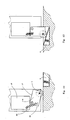
- seating 2 which contains the stop devices could form part of the structure of a gate or door, as will be illustrated with reference to figures 8 and 9.
- a box-shaped container 2 fitted to the bottom of gate 21 in correspondence with the free edge opposite the edge to which the hinges are fitted, forms a seating designed to receive door stop 3 which is normally kept pushed outwards, i.e. downwards, and designed to fit into a corresponding seating 4 in floor 5.
- door stop 3 consists of a mobile body, hinged to a fulcrum 6 and fitted with a wheel 7 at the bottom, which projects downwards from the gate and is normally maintained in this position, i.e. pushed towards the ground, by elastic means such as a spring 8 or the like, which is hooked onto the wall of seating 2.
- Door stop 3 can rotate around fulcrum 6 in such a way as to move from an upward recessed position in which it retracts completely inside the gate, with the wheel resting on the ground (fig. 8), to an operating position in which it projects from the gate and is inserted into seating 4 in the ground (fig. 7).
- Seating 4 is located in a position on the floor corresponding to the position of the free edge of the gate when the gate is in the maximum opening or closing position.
- the maximum outward extension of door stop 3 is determined when tooth 12, fitted to the top of door stop 3, comes to rest against a fixed rebate 13 in seating 2 (fig. 7) or in the door structure (fig. 8).
- This stop device for side-hinged gates and the like operates as follows.
- the stop device When the gate is in a position other than the maximum opening or closing position, the stop device is in the condition shown in figure 8, with wheel 7 resting on the ground and its mobile support 3 fully retracted into the gate.
- door stop 3 which could be made to slide instead of rotate, or fitted to a vertically sliding shaft 14 which counteracts a spring 15, as shown in figure 9, or represented by variations in the design of hatch 9 which, as shown in figure 10, could be made in two parts with an accordion fold, or made with other parts more suitable for the same purpose.
- a rotating support 16 is hinged to the gate structure in proximity to a corner and can rotate through an angle which, in the case illustrated, is approximately 90 degrees, between two extreme positions in which a pair of adjacent sides 17 and 18 thereof engage with the edge of a fixed rebate 19.
- a spring 20 tends to force support 16 into the position illustrated in figure 12, in which it projects from the gate, is inserted into seating 4, and engages with the wall of the said seating.
- FIG. 13 A further version of the device, designed to act as stop device in both the closing and opening positions of the gate, is illustrated in figure 13.
- box-shaped container 2 contains two supports 3 and 3' which are hinged to opposite sides of a support plate P.
- Supports 3 correspond substantially to the supports shown in figures 1 and 2, but are fitted symmetrically in relation to their common axis of rotation.
- the two supports can stop the movement of the gate in both directions.
- a stop device for the opening of gates and the like is thus obtained without parts projecting from the ground, and the risks and drawbacks they present.
- the arched contour of the lower edge of the two supports helps them to slide against the edge of seating 4 when the gate movement is reversed.
Landscapes
- Engineering & Computer Science (AREA)
- Mechanical Engineering (AREA)
- Gates (AREA)
Applications Claiming Priority (4)
| Application Number | Priority Date | Filing Date | Title |
|---|---|---|---|
| IT2001PC000022A ITPC20010022A1 (it) | 2001-07-12 | 2001-07-12 | Dispositivo di fine-corsa per cancelli, portoni e/o porte ad aperturaautomatica o simili. |
| ITPC20010022 | 2001-07-12 | ||
| ITPC20020015 | 2002-05-17 | ||
| ITPC20020015 ITPC20020015A1 (it) | 2002-05-17 | 2002-05-17 | Dispositivo di fine-corsa per cancelli, portone e/o porte ad aperturaautomatica o simili. |
Publications (2)
| Publication Number | Publication Date |
|---|---|
| EP1275806A2 true EP1275806A2 (de) | 2003-01-15 |
| EP1275806A3 EP1275806A3 (de) | 2004-06-02 |
Family
ID=26332803
Family Applications (1)
| Application Number | Title | Priority Date | Filing Date |
|---|---|---|---|
| EP02015225A Withdrawn EP1275806A3 (de) | 2001-07-12 | 2002-07-09 | Haltevorrichtung für Tore, Türen, automatische Türen oder dergleichen |
Country Status (1)
| Country | Link |
|---|---|
| EP (1) | EP1275806A3 (de) |
Cited By (5)
| Publication number | Priority date | Publication date | Assignee | Title |
|---|---|---|---|---|
| EP1405977A3 (de) * | 2002-10-02 | 2004-06-02 | DORMA GmbH + Co. KG | Türstoppsystem |
| CN103485627A (zh) * | 2013-10-12 | 2014-01-01 | 张继宇 | 机械牵引隐现式门吸 |
| DE102012108157B3 (de) * | 2012-09-03 | 2014-05-22 | Bombardier Transportation Gmbh | Schienenfahrzeug mit einer Schiebetür und Schienenfahrzeugwagen mit einer WC-Einheit |
| GR1009754B (el) * | 2019-08-26 | 2020-05-29 | Δημητριος Στυλιανου Γκατζουρας | Τροχος αναστολης και ελεγχου κινησης πορτας |
| US11661779B2 (en) * | 2016-06-29 | 2023-05-30 | Assa Abloy Entrance Systems Ab | Floor pit covering system |
Family Cites Families (4)
| Publication number | Priority date | Publication date | Assignee | Title |
|---|---|---|---|---|
| DE864220C (de) * | 1951-05-11 | 1953-01-22 | Ver Baubeschlag Gretsch Co | Tuerfeststellvorrichtung |
| DE1036106B (de) * | 1956-05-18 | 1958-08-07 | Ver Baubeschlag Gretsch Co | Feststelleinrichtung fuer Tueren |
| US2973215A (en) * | 1957-10-31 | 1961-02-28 | Loyd C Johnson | Door latch |
| US3239261A (en) * | 1961-01-24 | 1966-03-08 | Bryson | Door holders and stops |
-
2002
- 2002-07-09 EP EP02015225A patent/EP1275806A3/de not_active Withdrawn
Cited By (5)
| Publication number | Priority date | Publication date | Assignee | Title |
|---|---|---|---|---|
| EP1405977A3 (de) * | 2002-10-02 | 2004-06-02 | DORMA GmbH + Co. KG | Türstoppsystem |
| DE102012108157B3 (de) * | 2012-09-03 | 2014-05-22 | Bombardier Transportation Gmbh | Schienenfahrzeug mit einer Schiebetür und Schienenfahrzeugwagen mit einer WC-Einheit |
| CN103485627A (zh) * | 2013-10-12 | 2014-01-01 | 张继宇 | 机械牵引隐现式门吸 |
| US11661779B2 (en) * | 2016-06-29 | 2023-05-30 | Assa Abloy Entrance Systems Ab | Floor pit covering system |
| GR1009754B (el) * | 2019-08-26 | 2020-05-29 | Δημητριος Στυλιανου Γκατζουρας | Τροχος αναστολης και ελεγχου κινησης πορτας |
Also Published As
| Publication number | Publication date |
|---|---|
| EP1275806A3 (de) | 2004-06-02 |
Similar Documents
| Publication | Publication Date | Title |
|---|---|---|
| EP1694547B1 (de) | Fluchtvorrichtung für ein schienenfahrzeug | |
| RU2526924C2 (ru) | Дорожное устройство, а именно люк с рамой и затвором, снабженным обратным ходом относительно рамы, обеспечивающим закрытое положение затвора в раме | |
| US20200087964A1 (en) | Security gate with closer system | |
| US4318559A (en) | Lock for sliding members | |
| EP1275806A2 (de) | Haltevorrichtung für Tore, Türen, automatische Türen oder dergleichen | |
| KR100830570B1 (ko) | Psd용 구동부 커버의 개폐 장치 | |
| US6681525B1 (en) | Handicapped train-station gate | |
| RU201449U1 (ru) | Рельсовое транспортное средство с подвижной частью пола в дверном проёме | |
| US7997028B2 (en) | Internal swivel door for compartment of a vehicle | |
| US2681699A (en) | Garage door | |
| US7516514B2 (en) | Door stopper for a motor vehicle door and motor vehicle door for a motor vehicle with a door stopper of this type | |
| US1412871A (en) | Door | |
| GB2101192A (en) | Securing devices for closures | |
| KR100808649B1 (ko) | 지하철 스크린도어용 비상도어 | |
| EP3765691B1 (de) | Kabine mit türverriegelungsvorrichtung mit notzugriff | |
| KR200230637Y1 (ko) | 전동차량의 안전발판 | |
| KR100328395B1 (ko) | 자동도어 장치 | |
| KR200485812Y1 (ko) | 안전성이 강화된 선박용 난간 출입장치 | |
| NZ726011A (en) | Overhead door highwind retention system | |
| KR20080036571A (ko) | 절첩식 무빙 도어 장치 | |
| CN114531871B (zh) | 电梯设备 | |
| EP3026205A1 (de) | Garagentortropfschutz | |
| EP1582404A2 (de) | Sicherheitseinrichtung für Fahrzeugrampe | |
| FR2725971A1 (fr) | Dispositif d'acces au fonds de cuvette des ascenseurs | |
| JPS5938859Y2 (ja) | レ−ルからの外れを防止した戸車装置 |
Legal Events
| Date | Code | Title | Description |
|---|---|---|---|
| PUAI | Public reference made under article 153(3) epc to a published international application that has entered the european phase |
Free format text: ORIGINAL CODE: 0009012 |
|
| AK | Designated contracting states |
Kind code of ref document: A2 Designated state(s): AT BE BG CH CY CZ DE DK EE ES FI FR GB GR IE IT LI LU MC NL PT SE SK TR |
|
| AX | Request for extension of the european patent |
Free format text: AL;LT;LV;MK;RO;SI |
|
| PUAL | Search report despatched |
Free format text: ORIGINAL CODE: 0009013 |
|
| AK | Designated contracting states |
Kind code of ref document: A3 Designated state(s): AT BE BG CH CY CZ DE DK EE ES FI FR GB GR IE IT LI LU MC NL PT SE SK TR |
|
| AX | Request for extension of the european patent |
Extension state: AL LT LV MK RO SI |
|
| RIC1 | Information provided on ipc code assigned before grant |
Ipc: 7E 05F 5/02 B Ipc: 7E 05C 17/50 B Ipc: 7E 05F 5/08 A |
|
| AKX | Designation fees paid | ||
| REG | Reference to a national code |
Ref country code: DE Ref legal event code: 8566 |
|
| STAA | Information on the status of an ep patent application or granted ep patent |
Free format text: STATUS: THE APPLICATION IS DEEMED TO BE WITHDRAWN |
|
| 18D | Application deemed to be withdrawn |
Effective date: 20050201 |