EP1276175A1 - Connecteur hybride - Google Patents
Connecteur hybride Download PDFInfo
- Publication number
- EP1276175A1 EP1276175A1 EP02015508A EP02015508A EP1276175A1 EP 1276175 A1 EP1276175 A1 EP 1276175A1 EP 02015508 A EP02015508 A EP 02015508A EP 02015508 A EP02015508 A EP 02015508A EP 1276175 A1 EP1276175 A1 EP 1276175A1
- Authority
- EP
- European Patent Office
- Prior art keywords
- module
- locking
- grid
- locking means
- gate
- Prior art date
- Legal status (The legal status is an assumption and is not a legal conclusion. Google has not performed a legal analysis and makes no representation as to the accuracy of the status listed.)
- Granted
Links
Images



Classifications
-
- H—ELECTRICITY
- H01—ELECTRIC ELEMENTS
- H01R—ELECTRICALLY-CONDUCTIVE CONNECTIONS; STRUCTURAL ASSOCIATIONS OF A PLURALITY OF MUTUALLY-INSULATED ELECTRICAL CONNECTING ELEMENTS; COUPLING DEVICES; CURRENT COLLECTORS
- H01R13/00—Details of coupling devices of the kinds covered by groups H01R12/70 or H01R24/00 - H01R33/00
- H01R13/40—Securing contact members in or to a base or case; Insulating of contact members
- H01R13/42—Securing in a demountable manner
- H01R13/436—Securing a plurality of contact members by one locking piece or operation
- H01R13/4361—Insertion of locking piece perpendicular to direction of contact insertion
- H01R13/4362—Insertion of locking piece perpendicular to direction of contact insertion comprising a temporary and a final locking position
-
- H—ELECTRICITY
- H01—ELECTRIC ELEMENTS
- H01R—ELECTRICALLY-CONDUCTIVE CONNECTIONS; STRUCTURAL ASSOCIATIONS OF A PLURALITY OF MUTUALLY-INSULATED ELECTRICAL CONNECTING ELEMENTS; COUPLING DEVICES; CURRENT COLLECTORS
- H01R13/00—Details of coupling devices of the kinds covered by groups H01R12/70 or H01R24/00 - H01R33/00
- H01R13/44—Means for preventing access to live contacts
- H01R13/447—Shutter or cover plate
- H01R13/453—Shutter or cover plate opened by engagement of counterpart
- H01R13/4538—Covers sliding or withdrawing in the direction of engagement
Definitions
- the present invention relates to a connector hybrid electrical system comprising a contact holder module having pin contacts.
- Pins contact pins are known, designed to be coupled to female contact holder modules.
- the pin contact carrier module comprises a series of contact pins of small diameter, for example less than 1 mm, in particular less than or equal to about 0.64 mm. Such pins are fragile and require protection prior to mating with female contacts of a female module.
- Connector modules are also known whose locking contacts uses a shutter device equipped with finger locking contacts, these fingers to be inserted into windows in the contacts are supported on a rear wall of contact.
- the object of the invention is in particular to remedy these problems.
- the means locking is a movable locking flap, advantageously pivotally mounted on the body or sliding relative to the body, or a comb of locking.
- the body has a front end, a rear end, and a room in which the grid moves, this room having an opening before facing towards the front end of the body and a back part adjacent pin contacts, this end being turned towards the back end of the body, the grid being movable in said chamber between a position adjacent front of the body opening and a position adjacent back of alveoli receiving the bodies of contacts and letting the pin contacts pass.
- the grid has one or more first fingers pointing to the rear end of the body.
- the grid also has one or several second fingers directed towards the front end of the body or the opening of the chamber, the one or more second fingers directed towards the front end being arranged to cooperate with a locking means of a complementary module, this locking means abutting against an element of the grid in case correct non-locking by means of locking said complementary module and prohibiting the coupling of the modules.
- a return element or spring acts on the grid to exert a force tending to push the grid towards the front opening of the module.
- the module comprises one or short-circuit means for short-circuiting one or more contacts, said short-circuit means being movable between a short-circuit position and a short-circuit position. non-short circuit, said short-circuit means being controlled by the grid of the module in question or by an element of a module partially inserted into the module in question.
- the contact short-circuit means (s) are controlled by the gate, the one or more short-circuit means being deactivated when one or more fingers of the gate are engaged in a receiving notch of the gate. locking means.
- the short-circuit means include contact blades, presenting advantageously a curved end portion or folded.
- the blades of contact acts as a means of recall or spring tending to push the gate towards the front opening of the module.
- Another subject of the invention is the use of one or modules according to the invention for producing coupling connectors between contact pins small diameter and female contacts.
- the body 1 has a front end 1A and a rear end 1B, the chamber 7 being open from side of the end 1A. This opening of the room being adapted to allow the engagement of a party a module door contact female in the room.
- Each flap 4, 5 comprises clipping means 9 cooperating with body 1 means to ensure the keeping the shutter in the locked position.
- Each flap 4, 5 consists of two lugs 10, 11 between which extends a plate 12 carrying the lugs 26.
- Each lug 10, 11 is profiled so as to form a channel 13 and a stop 14.
- the leg 10, 11 has a profile substantially in L.
- the gate 6 bears on its face turned towards the bottom of the chamber or towards the end 1B of the body four 15A, 15B (FIGS. 4 and 6), two being located on the along the left edge 16 of the grid, while the two others are located along the right edge 17 of the grid 6.
- the upper fingers 15A are intended for cooperate with the tabs 10, 11 of the upper flap 5, while the lower fingers 15B are intended for cooperate with the lugs 10, 11 of the lower flap 4.
- each finger 15A, 15B of the grid 6 is located respectively in front of a channel 13 of a leg 10, 11 of a component 4, 5.
- each finger 15A, 15B is adapted to be engaged in a channel 13 during a movement of the gate towards the end back of the body 1.
- the fingers 15A, 15B serve as means opposing the opening of shutters 4, 5.
- the fingers 15A, 15B prevent any voluntary opening or accidental flaps 4, 5.
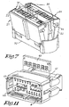
- a female module 21 able to cooperate with the module of FIG. 1 is schematically shown in FIG. FIG. 7.
- This female module comprises, for example also two contact locking flaps 22 females 23.
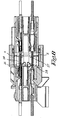
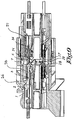
- the module of Figure 1 also includes blades short circuit 24 (FIGS. 8, 9 and 10) forming a short circuit of contacts as long as the module is not coupled to the female module.
- the elastic blades 24 act in the position of the figure 10 on the grid to push her towards the opening of room 7. Thus, during the uncoupling of the module of FIG. that of Figure 7, the elastic blades 24 push on the grid so as to ensure good protection pins from the beginning of the operation of separation of modules.
- the female module 21 (FIG. 7) has studs and pre-locking slots 30 and one or more pads and Final locking notches 31.
- the module presents also a polarization key 32 to be engaged in a throat 33 of room 7 of the body 1 (figure 1).
- the female module also has two 34 fooling fingers intended to be engaged in throats 35 of the chamber 7 when connecting the module of Figure 1 with the module of Figure 7.
- the polarization key 32 and the foolproof fingers 34 make it possible to avoid coupling the modules in in the opposite direction, but above all linear motion of the female module 21 with respect to the room 7.
- the flaps 22 may be of a similar type to that shown for the module of Figure 1, while the grid 6 has fingers (shown in broken lines in Figure 6 under the reference 15bis) turned towards the opening of Chamber 7. These 15bis fingers are meant to be engaged respectively in a channel of a paw of a shutter when the flaps 22 are in the locked position. These fingers 15a thus provide a function of because they prevent an opening accidental or not of a flap 22 during the coupling of the module 21 with the module of the figure 1.
- FIG 11 shows in perspective a similar module to that shown in Figure 1, except that this module has a locking comb 40 for inserted in a housing 41 of the module.
- This comb has notches 42 receiving rods 43 (shown in broken lines) in solidarity with the grid 6.
- the grid 6 also includes rods 44 turned forward and intended to work with a other module.
- each module may include pins and female parts.
- each module advantageously comprises a protection grid.
- the locking flap may be a non-pivoting flap, for example sliding.
- a separate locking system can be used to lock a shutter.
- this system of lock has a notch or window for receive a finger from the moving gate, when the locking system is in locked position.
Landscapes
- Details Of Connecting Devices For Male And Female Coupling (AREA)
- Coupling Device And Connection With Printed Circuit (AREA)
- Connector Housings Or Holding Contact Members (AREA)
- Diaphragms For Electromechanical Transducers (AREA)
Abstract
Description
De telles broches sont fragiles et nécessitent une protection avant leur accouplement avec des contacts femelles d'un module femelle.
- un corps adapté pour recevoir au moins des contacts broches;
- au moins un moyen de verrouillage des contacts broches, ce moyen étant mobile par rapport au corps entre une position de non verrouillage et une position de verrouillage correct ;
- une grille avant montée mobile par rapport au corps entre une position avancée de protection des contacts broches et une position reculée permettant l'accouplement du module avec un module complémentaire,
- un doigt ou une tige solidaire du moyen de verrouillage ou de la grille mobile, et,
- une encoche formée dans la grille avant ou le moyen de verrouillage pour recevoir respectivement le doigt ou la tige solidaire du moyen de verrouillage ou le doigt ou la tige solidaire de la grille mobile, et
- une butée que présente la grille ou le moyen de verrouillage,
De préférence, le ou les moyens de court-circuit de contact(s) sont commandés par la grille, le ou lesdits moyens de court-circuit étant désactivés lorsqu'un un ou des doigts de la grille sont engagés dans une encoche de réception du moyen de verrouillage.
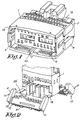
- La figure 1 est une vue d'ensemble d'un module comportant deux volets pivotants ;
- La figure 2 est une vue partielle en perspective du module de la figure 1, montrant les volets en position ouverte ;
- La figure 3 est une vue en perspective avec arrachement du module de la figure 1, avec les volets rabattus mais non en position verrouillée ;
- La figure 4 est une vue schématique montrant la position de la grille par rapport au volet supérieur du module dans la position de la figure 3 ;
- La figure 5 est une vue similaire à celle de la figure 3 si ce n'est que les volets sont en position verrouillée ;
- La figure 6 est une vue schématique montrant la position de la grille par rapport au volet supérieur du module de la figure 5 ;
- La figure 7 est une vue en perspective d'un module femelle coopérant avec le module de la figure 1 ;
- La figure 8 est une vue en coupe montrant l'introduction du module femelle dans le module mâle de la figure 1 ;
- La figure 9 est une vue en coupe montrant le module femelle partiellement accouplé au module mâle de la figure 1 ;
- La figure 10 est une vue en coupe montrant le module femelle accouplé au module mâle de la figure 1 ;
- La figure 11 est une vue schématique d'un module similaire à celui représenté à la figure 1, si ce n'est qu'il comporte un peigne de verrouillage.
- un corps 1 comportant une série de logements ou alvéoles 2 recevant des contacts broches 3 comportant un corps 3B reçu dans un alvéole 2 et une terminaison de contact 3A complémentaire d'un contact femelle complémentaire 23, 51;
- un volet inférieur 4 et un volet supérieur 5 présentant une série d'ergots de verrouillage 26 pour assurer le maintien en place des contacts broches 3, les volets 4, 5 étant montés à pivotement par rapport au corps 1 ;
- une grille de protection 6 placée dans une chambre 7 du corps 1, cette grille étant mobile par rapport au corps 1 et présente une série de passages 8 pour les extrémités des broches 3A lors de l'accouplement du module avec un module porte contacts femelles complémentaire.
A la figure 4, on a représenté le volet supérieur 5 et la grille 6 distants l'un de l'autre. La ligne interrompue 18 montre la position du doigt 15A par rapport à la patte 11. En réalité le doigt 15A est adjacent de la patte 11.
Le volet de verrouillage peut être un volet non pivotant, par exemple coulissant.
Claims (11)
- Module porte contacts comportant :caractérisé en ce que le module porte contacts comporte un moyen de blocage (14, 15A, 15B) s'opposant à un mouvement de la grille (6) en cas de non verrouillage correct des contacts par le moyen de verrouillage.un corps (1) adapté pour recevoir au moins des contacts broches;au moins un moyen de verrouillage (4, 5) desdits contacts, ce moyen de verrouillage étant mobile par rapport au corps (1) entre une position de non verrouillage et une position de verrouillage correct des contacts;une grille avant (6) montée mobile par rapport au corps entre une position avancée de protection des contacts broches et une position reculée permettant l'accouplement du module porte contacts avec un module complémentaire,
- Module suivant la revendication 1, caractérisé en ce que le moyen de blocage s'opposant à un mouvement de la grille en cas de non verrouillage correct par le moyen de verrouillage comporte :dans lequel l'encoche (13) et la butée (14) sont agencées de manière à permettre, en cas de verrouillage correct par le moyen de verrouillage, un mouvement de la grille grâce à l'engagement du doigt ou tige dans une encoche (13) lors d'un mouvement de la grille (6), et de manière, en cas de verrouillage incorrect, à ce que le doigt ou tige (15A, 15B) bute sur la butée (14) pour s'opposer à un mouvement de la grille (6).un doigt ou une tige (15A, 15B) solidaire du moyen de verrouillage ou de la grille avant mobile (6), etune encoche (13) formée dans la grille avant ou le moyen de verrouillage (4, 5) pour recevoir respectivement le doigt ou la tige solidaire du moyen de verrouillage ou le doigt ou la tige solidaire (15A, 15B) de la grille avant mobile (6), etune butée (14) que présente la grille ou le moyen de verrouillage (4, 5),
- Module suivant la revendication 1 ou 2, caractérisé en ce que le moyen de verrouillage est un volet mobile de verrouillage (4, 5), avantageusement monté à pivotement sur le corps (1) ou à glissement par rapport au corps, ou un peigne de verrouillage (40).
- Module suivant l'une quelconque des revendications précédentes, caractérisé en ce que le corps (1) présente une extrémité avant (1A), une extrémité arrière (1B), et une chambre (7) dans laquelle se déplace la grille (6), cette chambre (7) présentant une ouverture avant tournée vers l'extrémité avant (1A) du corps (1) et une partie arrière adjacente des corps (3B) des contacts broches (3), cette extrémité étant tournée vers l'extrémité arrière (1B) du corps (1), la grille (6) étant mobile dans ladite chambre (7) entre une position avancée de protection des broches adjacente de l'ouverture du corps et une position arrière adjacente des alvéoles 2 recevant les corps de contacts broches et laissant passer les terminaisons 3A des contacts broches 3.
- Module suivant la revendication 4, caractérisé en ce que la grille (6) présente un ou des premiers doigts (15A,15B) dirigés vers l'extrémité arrière (1B) du corps (1).
- Module suivant la revendication 5, caractérisé en ce que la grille (6) présente en outre un ou des seconds doigts (15bis) dirigés vers l'extrémité avant (1A) du corps (1) ou l'ouverture de la chambre (7), le ou lesdits seconds doigts (15bis) dirigés vers l'extrémité avant étant agencés pour coopérer avec un moyen de verrouillage d'un module (21) complémentaire, ce moyen de verrouillage venant en butée contre un élément de la grille (6) en cas de non verrouillage correct par le moyen de verrouillage dudit module complémentaire et interdisant l'accouplement des modules.
- Module suivant l'une quelconque des revendications précédentes, caractérisé en ce qu'un élément de rappel ou ressort (29) agit sur la grille (6) pour exercer une force tendant à pousser la grille (6) vers l'ouverture avant (1A) du module.
- Module suivant l'une des revendications précédentes, caractérisé en ce qu'il comporte un ou des moyens de court-circuit (24) d'un ou plusieurs contacts, le ou lesdits moyens de court-circuit étant mobile entre une position de court-circuit et une position de non court-circuit, le ou lesdits moyens de court-circuit étant commandés par la grille (6) du module considéré.
- Module suivant la revendication précédente, caractérisé en ce que le ou lesdits moyens de court-circuit (24) sont désactivés lorsqu'un ou des doigts (15A, 15B) de la grille (6) sont engagés dans une encoche (13) de réception du moyen de verrouillage (4, 5).
- Module suivant la revendication précédente, caractérisé en ce que le ou les moyens de court-circuit (24) comprennent des lames de contact, présentant avantageusement une partie terminale (28) recourbée ou pliée.
- Module suivant la revendication précédente, caractérisé en ce que les lames de contact (24) joue un rôle de moyen de rappel ou ressort tendant à pousser la grille (6) vers l'ouverture avant (1A) du module, au moins au début d'une opération de déconnexion.
Applications Claiming Priority (2)
| Application Number | Priority Date | Filing Date | Title |
|---|---|---|---|
| FR0109432A FR2827431A1 (fr) | 2001-07-10 | 2001-07-10 | Connecteur hybride |
| FR0109432 | 2001-07-10 |
Publications (2)
| Publication Number | Publication Date |
|---|---|
| EP1276175A1 true EP1276175A1 (fr) | 2003-01-15 |
| EP1276175B1 EP1276175B1 (fr) | 2008-05-28 |
Family
ID=8865529
Family Applications (1)
| Application Number | Title | Priority Date | Filing Date |
|---|---|---|---|
| EP02015508A Expired - Lifetime EP1276175B1 (fr) | 2001-07-10 | 2002-07-10 | Connecteur hybride |
Country Status (5)
| Country | Link |
|---|---|
| EP (1) | EP1276175B1 (fr) |
| AT (1) | ATE397308T1 (fr) |
| DE (1) | DE60226812D1 (fr) |
| ES (1) | ES2304410T3 (fr) |
| FR (1) | FR2827431A1 (fr) |
Cited By (3)
| Publication number | Priority date | Publication date | Assignee | Title |
|---|---|---|---|---|
| FR2864357A1 (fr) * | 2003-12-19 | 2005-06-24 | Framatome Connectors Int | Dispositif de verrouillage de contacts pour connecteur electrique et connecteur electrique le comprenant |
| US8469752B2 (en) | 2009-07-20 | 2013-06-25 | Delphi International Operations Luxembourg, S.Ar.L | Electrical connector having shorting bar operation device |
| FR3013519A1 (fr) * | 2013-11-19 | 2015-05-22 | Filec | Connecteur electrique destine a etre place au sein d'un volant de direction de vehicule automobile |
Citations (4)
| Publication number | Priority date | Publication date | Assignee | Title |
|---|---|---|---|---|
| DE19704356A1 (de) * | 1996-02-05 | 1997-08-07 | Yazaki Corp | Steckverbinder mit einem Teil zum Erfassen des Eingriffs von Anschlußstücken |
| US5913697A (en) * | 1996-12-10 | 1999-06-22 | The Whitaker Corporation | Electrical connector having a secondary lock |
| US5964621A (en) * | 1998-06-25 | 1999-10-12 | The Whitaker Corporation | Connector assembly for multi-pocket header |
| US5997365A (en) * | 1997-03-10 | 1999-12-07 | Yazaki Corporation | Connector |
-
2001
- 2001-07-10 FR FR0109432A patent/FR2827431A1/fr active Pending
-
2002
- 2002-07-10 AT AT02015508T patent/ATE397308T1/de not_active IP Right Cessation
- 2002-07-10 EP EP02015508A patent/EP1276175B1/fr not_active Expired - Lifetime
- 2002-07-10 DE DE60226812T patent/DE60226812D1/de not_active Expired - Lifetime
- 2002-07-10 ES ES02015508T patent/ES2304410T3/es not_active Expired - Lifetime
Patent Citations (4)
| Publication number | Priority date | Publication date | Assignee | Title |
|---|---|---|---|---|
| DE19704356A1 (de) * | 1996-02-05 | 1997-08-07 | Yazaki Corp | Steckverbinder mit einem Teil zum Erfassen des Eingriffs von Anschlußstücken |
| US5913697A (en) * | 1996-12-10 | 1999-06-22 | The Whitaker Corporation | Electrical connector having a secondary lock |
| US5997365A (en) * | 1997-03-10 | 1999-12-07 | Yazaki Corporation | Connector |
| US5964621A (en) * | 1998-06-25 | 1999-10-12 | The Whitaker Corporation | Connector assembly for multi-pocket header |
Cited By (7)
| Publication number | Priority date | Publication date | Assignee | Title |
|---|---|---|---|---|
| FR2864357A1 (fr) * | 2003-12-19 | 2005-06-24 | Framatome Connectors Int | Dispositif de verrouillage de contacts pour connecteur electrique et connecteur electrique le comprenant |
| WO2005069686A1 (fr) * | 2003-12-19 | 2005-07-28 | Fci | Dispositif de verrouillage de contacts pour connecteur electrique et connecteur electrique le comprenant |
| JP2007517362A (ja) * | 2003-12-19 | 2007-06-28 | エフシーアイ | 電気コネクター用コンタクト錠止デバイス及び前記デバイスを含む電気コンテナ |
| US7578709B2 (en) | 2003-12-19 | 2009-08-25 | Fci | Contact locking device for an electric connector and electric connector containing said device |
| CN100551173C (zh) * | 2003-12-19 | 2009-10-14 | Fci公司 | 用于电连接器的接头锁定装置以及包含所述装置的电连接器 |
| US8469752B2 (en) | 2009-07-20 | 2013-06-25 | Delphi International Operations Luxembourg, S.Ar.L | Electrical connector having shorting bar operation device |
| FR3013519A1 (fr) * | 2013-11-19 | 2015-05-22 | Filec | Connecteur electrique destine a etre place au sein d'un volant de direction de vehicule automobile |
Also Published As
| Publication number | Publication date |
|---|---|
| FR2827431A1 (fr) | 2003-01-17 |
| DE60226812D1 (de) | 2008-07-10 |
| ES2304410T3 (es) | 2008-10-16 |
| EP1276175B1 (fr) | 2008-05-28 |
| ATE397308T1 (de) | 2008-06-15 |
Similar Documents
| Publication | Publication Date | Title |
|---|---|---|
| EP0681345A1 (fr) | Organe de contact électrique hermaphrodite | |
| EP2109189A1 (fr) | Dispositif de verrouillage d'éléments de connecteur et connecteur le comprénant | |
| FR3049778A1 (fr) | Connecteur electrique a dispositif d'assurance de position de connecteur rotatif | |
| FR2805403A1 (fr) | Connecteur a levier | |
| FR2889365A1 (fr) | Connecteur du type a levier pivotant | |
| EP2456021B1 (fr) | Prise électrique comportant des montants latéraux mobiles en translation | |
| EP1276175B1 (fr) | Connecteur hybride | |
| FR2706687A1 (fr) | Elément de boîtier de connecteur électrique. | |
| EP0723314A1 (fr) | Connecteur électrique | |
| EP0207841A1 (fr) | Perfectionnements au montage des organes de connexions électriques | |
| EP0519815A1 (fr) | Connecteur électrique | |
| EP3062401A1 (fr) | Système de raccordement pour connecteur | |
| EP0673084A1 (fr) | Elément de boîtier de connecteur électrique | |
| EP1258949A1 (fr) | Système d'accrochage et éléments mettant en oeuvre ce système | |
| EP0677892B1 (fr) | Module porte-contact et connecteur le comprenant | |
| FR2932317A1 (fr) | Prise de courant universelle munie d'un obturateur de securite. | |
| FR2467490A1 (fr) | Organe de connexion electrique et boitier destine a contenir un tel organe | |
| FR2777392A1 (fr) | Connecteur electrique | |
| EP0949718B1 (fr) | Module de connexion/déconnexion de paires de conducteurs électriques isolés | |
| FR2696880A1 (fr) | Connecteur électrique à éléments de contact hermaphrodites. | |
| FR3106441A1 (fr) | Dispositif d’assemblage de fiche avec un dispositif d’assurance de position du connecteur | |
| EP1286427A1 (fr) | Bloc de jonction avec un bras de verrouillage pour connecteur enfichable | |
| FR3010578A1 (fr) | Connecteur a dispositif d'assurance de position electrique | |
| FR2828339A1 (fr) | Systeme de raccordement pour un reseau specifique de distribution de courant, et adaptateur a coiffe pour broche de terre de fiche et socle de prise correspondants | |
| FR2785728A1 (fr) | Assemblage de connecteurs electriques |
Legal Events
| Date | Code | Title | Description |
|---|---|---|---|
| PUAI | Public reference made under article 153(3) epc to a published international application that has entered the european phase |
Free format text: ORIGINAL CODE: 0009012 |
|
| AK | Designated contracting states |
Kind code of ref document: A1 Designated state(s): AT BE BG CH CY CZ DE DK EE ES FI FR GB GR IE IT LI LU MC NL PT SE SK TR |
|
| AX | Request for extension of the european patent |
Free format text: AL;LT;LV;MK;RO;SI |
|
| 17P | Request for examination filed |
Effective date: 20030702 |
|
| AKX | Designation fees paid |
Designated state(s): AT BE BG CH CY CZ DE DK EE ES FI FR GB GR IE IT LI LU MC NL PT SE SK TR |
|
| GRAP | Despatch of communication of intention to grant a patent |
Free format text: ORIGINAL CODE: EPIDOSNIGR1 |
|
| GRAS | Grant fee paid |
Free format text: ORIGINAL CODE: EPIDOSNIGR3 |
|
| GRAA | (expected) grant |
Free format text: ORIGINAL CODE: 0009210 |
|
| RAP1 | Party data changed (applicant data changed or rights of an application transferred) |
Owner name: FCI |
|
| AK | Designated contracting states |
Kind code of ref document: B1 Designated state(s): AT BE BG CH CY CZ DE DK EE ES FI FR GB GR IE IT LI LU MC NL PT SE SK TR |
|
| REG | Reference to a national code |
Ref country code: GB Ref legal event code: FG4D Free format text: NOT ENGLISH |
|
| REG | Reference to a national code |
Ref country code: CH Ref legal event code: EP |
|
| REF | Corresponds to: |
Ref document number: 60226812 Country of ref document: DE Date of ref document: 20080710 Kind code of ref document: P |
|
| REG | Reference to a national code |
Ref country code: IE Ref legal event code: FG4D Free format text: LANGUAGE OF EP DOCUMENT: FRENCH |
|
| REG | Reference to a national code |
Ref country code: ES Ref legal event code: FG2A Ref document number: 2304410 Country of ref document: ES Kind code of ref document: T3 |
|
| PG25 | Lapsed in a contracting state [announced via postgrant information from national office to epo] |
Ref country code: FI Free format text: LAPSE BECAUSE OF FAILURE TO SUBMIT A TRANSLATION OF THE DESCRIPTION OR TO PAY THE FEE WITHIN THE PRESCRIBED TIME-LIMIT Effective date: 20080528 |
|
| PG25 | Lapsed in a contracting state [announced via postgrant information from national office to epo] |
Ref country code: NL Free format text: LAPSE BECAUSE OF FAILURE TO SUBMIT A TRANSLATION OF THE DESCRIPTION OR TO PAY THE FEE WITHIN THE PRESCRIBED TIME-LIMIT Effective date: 20080528 Ref country code: AT Free format text: LAPSE BECAUSE OF FAILURE TO SUBMIT A TRANSLATION OF THE DESCRIPTION OR TO PAY THE FEE WITHIN THE PRESCRIBED TIME-LIMIT Effective date: 20080528 |
|
| NLV1 | Nl: lapsed or annulled due to failure to fulfill the requirements of art. 29p and 29m of the patents act | ||
| REG | Reference to a national code |
Ref country code: IE Ref legal event code: FD4D |
|
| PG25 | Lapsed in a contracting state [announced via postgrant information from national office to epo] |
Ref country code: SE Free format text: LAPSE BECAUSE OF FAILURE TO SUBMIT A TRANSLATION OF THE DESCRIPTION OR TO PAY THE FEE WITHIN THE PRESCRIBED TIME-LIMIT Effective date: 20080828 Ref country code: IE Free format text: LAPSE BECAUSE OF FAILURE TO SUBMIT A TRANSLATION OF THE DESCRIPTION OR TO PAY THE FEE WITHIN THE PRESCRIBED TIME-LIMIT Effective date: 20080528 Ref country code: PT Free format text: LAPSE BECAUSE OF FAILURE TO SUBMIT A TRANSLATION OF THE DESCRIPTION OR TO PAY THE FEE WITHIN THE PRESCRIBED TIME-LIMIT Effective date: 20081028 Ref country code: DK Free format text: LAPSE BECAUSE OF FAILURE TO SUBMIT A TRANSLATION OF THE DESCRIPTION OR TO PAY THE FEE WITHIN THE PRESCRIBED TIME-LIMIT Effective date: 20080528 Ref country code: CZ Free format text: LAPSE BECAUSE OF FAILURE TO SUBMIT A TRANSLATION OF THE DESCRIPTION OR TO PAY THE FEE WITHIN THE PRESCRIBED TIME-LIMIT Effective date: 20080528 |
|
| PG25 | Lapsed in a contracting state [announced via postgrant information from national office to epo] |
Ref country code: SK Free format text: LAPSE BECAUSE OF FAILURE TO SUBMIT A TRANSLATION OF THE DESCRIPTION OR TO PAY THE FEE WITHIN THE PRESCRIBED TIME-LIMIT Effective date: 20080528 |
|
| REG | Reference to a national code |
Ref country code: CH Ref legal event code: PL |
|
| PG25 | Lapsed in a contracting state [announced via postgrant information from national office to epo] |
Ref country code: MC Free format text: LAPSE BECAUSE OF NON-PAYMENT OF DUE FEES Effective date: 20080731 |
|
| PLBE | No opposition filed within time limit |
Free format text: ORIGINAL CODE: 0009261 |
|
| STAA | Information on the status of an ep patent application or granted ep patent |
Free format text: STATUS: NO OPPOSITION FILED WITHIN TIME LIMIT |
|
| GBPC | Gb: european patent ceased through non-payment of renewal fee |
Effective date: 20080828 |
|
| PG25 | Lapsed in a contracting state [announced via postgrant information from national office to epo] |
Ref country code: BG Free format text: LAPSE BECAUSE OF FAILURE TO SUBMIT A TRANSLATION OF THE DESCRIPTION OR TO PAY THE FEE WITHIN THE PRESCRIBED TIME-LIMIT Effective date: 20080828 Ref country code: EE Free format text: LAPSE BECAUSE OF FAILURE TO SUBMIT A TRANSLATION OF THE DESCRIPTION OR TO PAY THE FEE WITHIN THE PRESCRIBED TIME-LIMIT Effective date: 20080528 |
|
| 26N | No opposition filed |
Effective date: 20090303 |
|
| PG25 | Lapsed in a contracting state [announced via postgrant information from national office to epo] |
Ref country code: CH Free format text: LAPSE BECAUSE OF NON-PAYMENT OF DUE FEES Effective date: 20080731 Ref country code: LI Free format text: LAPSE BECAUSE OF NON-PAYMENT OF DUE FEES Effective date: 20080731 |
|
| PG25 | Lapsed in a contracting state [announced via postgrant information from national office to epo] |
Ref country code: IT Free format text: LAPSE BECAUSE OF FAILURE TO SUBMIT A TRANSLATION OF THE DESCRIPTION OR TO PAY THE FEE WITHIN THE PRESCRIBED TIME-LIMIT Effective date: 20080528 |
|
| PG25 | Lapsed in a contracting state [announced via postgrant information from national office to epo] |
Ref country code: GB Free format text: LAPSE BECAUSE OF NON-PAYMENT OF DUE FEES Effective date: 20080828 |
|
| PG25 | Lapsed in a contracting state [announced via postgrant information from national office to epo] |
Ref country code: LU Free format text: LAPSE BECAUSE OF NON-PAYMENT OF DUE FEES Effective date: 20080710 Ref country code: CY Free format text: LAPSE BECAUSE OF FAILURE TO SUBMIT A TRANSLATION OF THE DESCRIPTION OR TO PAY THE FEE WITHIN THE PRESCRIBED TIME-LIMIT Effective date: 20080528 Ref country code: BE Free format text: LAPSE BECAUSE OF NON-PAYMENT OF DUE FEES Effective date: 20080731 |
|
| PG25 | Lapsed in a contracting state [announced via postgrant information from national office to epo] |
Ref country code: TR Free format text: LAPSE BECAUSE OF FAILURE TO SUBMIT A TRANSLATION OF THE DESCRIPTION OR TO PAY THE FEE WITHIN THE PRESCRIBED TIME-LIMIT Effective date: 20080528 |
|
| PG25 | Lapsed in a contracting state [announced via postgrant information from national office to epo] |
Ref country code: GR Free format text: LAPSE BECAUSE OF FAILURE TO SUBMIT A TRANSLATION OF THE DESCRIPTION OR TO PAY THE FEE WITHIN THE PRESCRIBED TIME-LIMIT Effective date: 20080829 |
|
| REG | Reference to a national code |
Ref country code: FR Ref legal event code: CA |
|
| REG | Reference to a national code |
Ref country code: FR Ref legal event code: TP Owner name: FCI AUTOMOTIVE HOLDING, FR Effective date: 20110830 |
|
| REG | Reference to a national code |
Ref country code: FR Ref legal event code: GC Effective date: 20110908 |
|
| REG | Reference to a national code |
Ref country code: DE Ref legal event code: R081 Ref document number: 60226812 Country of ref document: DE Owner name: FCI AUTOMOTIVE HOLDING, FR Free format text: FORMER OWNER: FCI, VERSAILLES, FR Effective date: 20120419 Ref country code: DE Ref legal event code: R081 Ref document number: 60226812 Country of ref document: DE Owner name: DELPHI INTERNATIONAL OPERATIONS LUXEMBOURG S.A, LU Free format text: FORMER OWNER: FCI, VERSAILLES, FR Effective date: 20120419 |
|
| REG | Reference to a national code |
Ref country code: DE Ref legal event code: R081 Ref document number: 60226812 Country of ref document: DE Owner name: FCI AUTOMOTIVE HOLDING, FR Free format text: FORMER OWNER: FCI, GUYANCOURT, FR Effective date: 20120629 Ref country code: DE Ref legal event code: R081 Ref document number: 60226812 Country of ref document: DE Owner name: DELPHI INTERNATIONAL OPERATIONS LUXEMBOURG S.A, LU Free format text: FORMER OWNER: FCI, GUYANCOURT, FR Effective date: 20120629 |
|
| REG | Reference to a national code |
Ref country code: FR Ref legal event code: TP Owner name: DELPHI INTERNATIONAL OPERATIONS LUXEMBOURG S.A, LU Effective date: 20140715 |
|
| REG | Reference to a national code |
Ref country code: DE Ref legal event code: R082 Ref document number: 60226812 Country of ref document: DE Representative=s name: BARDEHLE PAGENBERG PARTNERSCHAFT MBB PATENTANW, DE |
|
| REG | Reference to a national code |
Ref country code: DE Ref legal event code: R081 Ref document number: 60226812 Country of ref document: DE Owner name: DELPHI INTERNATIONAL OPERATIONS LUXEMBOURG S.A, LU Free format text: FORMER OWNER: FCI AUTOMOTIVE HOLDING, GUYANCOURT, FR Effective date: 20141106 Ref country code: DE Ref legal event code: R082 Ref document number: 60226812 Country of ref document: DE Representative=s name: BARDEHLE PAGENBERG PARTNERSCHAFT MBB PATENTANW, DE Effective date: 20141106 |
|
| REG | Reference to a national code |
Ref country code: FR Ref legal event code: PLFP Year of fee payment: 15 |
|
| REG | Reference to a national code |
Ref country code: FR Ref legal event code: PLFP Year of fee payment: 16 |
|
| REG | Reference to a national code |
Ref country code: FR Ref legal event code: PLFP Year of fee payment: 17 |
|
| REG | Reference to a national code |
Ref country code: DE Ref legal event code: R082 Ref document number: 60226812 Country of ref document: DE Ref country code: DE Ref legal event code: R081 Ref document number: 60226812 Country of ref document: DE Owner name: APTIV TECHNOLOGIES LIMITED, BB Free format text: FORMER OWNER: DELPHI INTERNATIONAL OPERATIONS LUXEMBOURG S.A R.L., BASCHARAGE, LU |
|
| PGFP | Annual fee paid to national office [announced via postgrant information from national office to epo] |
Ref country code: FR Payment date: 20210719 Year of fee payment: 20 |
|
| PGFP | Annual fee paid to national office [announced via postgrant information from national office to epo] |
Ref country code: DE Payment date: 20210721 Year of fee payment: 20 Ref country code: ES Payment date: 20210809 Year of fee payment: 20 |
|
| REG | Reference to a national code |
Ref country code: DE Ref legal event code: R071 Ref document number: 60226812 Country of ref document: DE |
|
| REG | Reference to a national code |
Ref country code: ES Ref legal event code: FD2A Effective date: 20220727 |
|
| PG25 | Lapsed in a contracting state [announced via postgrant information from national office to epo] |
Ref country code: ES Free format text: LAPSE BECAUSE OF EXPIRATION OF PROTECTION Effective date: 20220711 |