EP1277910A1 - Schwellenlose Türe mit absenkbarer Dichtung - Google Patents
Schwellenlose Türe mit absenkbarer Dichtung Download PDFInfo
- Publication number
- EP1277910A1 EP1277910A1 EP02405324A EP02405324A EP1277910A1 EP 1277910 A1 EP1277910 A1 EP 1277910A1 EP 02405324 A EP02405324 A EP 02405324A EP 02405324 A EP02405324 A EP 02405324A EP 1277910 A1 EP1277910 A1 EP 1277910A1
- Authority
- EP
- European Patent Office
- Prior art keywords
- door
- profile
- seal
- sealing
- door leaf
- Prior art date
- Legal status (The legal status is an assumption and is not a legal conclusion. Google has not performed a legal analysis and makes no representation as to the accuracy of the status listed.)
- Granted
Links
Images


Classifications
-
- E—FIXED CONSTRUCTIONS
- E06—DOORS, WINDOWS, SHUTTERS, OR ROLLER BLINDS IN GENERAL; LADDERS
- E06B—FIXED OR MOVABLE CLOSURES FOR OPENINGS IN BUILDINGS, VEHICLES, FENCES OR LIKE ENCLOSURES IN GENERAL, e.g. DOORS, WINDOWS, BLINDS, GATES
- E06B7/00—Special arrangements or measures in connection with doors or windows
- E06B7/16—Sealing arrangements on wings or parts co-operating with the wings
- E06B7/18—Sealing arrangements on wings or parts co-operating with the wings by means of movable edgings, e.g. draught sealings additionally used for bolting, e.g. by spring force or with operating lever
- E06B7/20—Sealing arrangements on wings or parts co-operating with the wings by means of movable edgings, e.g. draught sealings additionally used for bolting, e.g. by spring force or with operating lever automatically withdrawn when the wing is opened, e.g. by means of magnetic attraction, a pin or an inclined surface, especially for sills
- E06B7/21—Sealing arrangements on wings or parts co-operating with the wings by means of movable edgings, e.g. draught sealings additionally used for bolting, e.g. by spring force or with operating lever automatically withdrawn when the wing is opened, e.g. by means of magnetic attraction, a pin or an inclined surface, especially for sills with sealing strip movable in plane of wing
-
- E—FIXED CONSTRUCTIONS
- E06—DOORS, WINDOWS, SHUTTERS, OR ROLLER BLINDS IN GENERAL; LADDERS
- E06B—FIXED OR MOVABLE CLOSURES FOR OPENINGS IN BUILDINGS, VEHICLES, FENCES OR LIKE ENCLOSURES IN GENERAL, e.g. DOORS, WINDOWS, BLINDS, GATES
- E06B3/00—Window sashes, door leaves, or like elements for closing wall or like openings; Layout of fixed or moving closures, e.g. windows in wall or like openings; Features of rigidly-mounted outer frames relating to the mounting of wing frames
- E06B3/02—Wings made completely of glass
-
- E—FIXED CONSTRUCTIONS
- E06—DOORS, WINDOWS, SHUTTERS, OR ROLLER BLINDS IN GENERAL; LADDERS
- E06B—FIXED OR MOVABLE CLOSURES FOR OPENINGS IN BUILDINGS, VEHICLES, FENCES OR LIKE ENCLOSURES IN GENERAL, e.g. DOORS, WINDOWS, BLINDS, GATES
- E06B7/00—Special arrangements or measures in connection with doors or windows
- E06B7/16—Sealing arrangements on wings or parts co-operating with the wings
- E06B7/18—Sealing arrangements on wings or parts co-operating with the wings by means of movable edgings, e.g. draught sealings additionally used for bolting, e.g. by spring force or with operating lever
- E06B7/20—Sealing arrangements on wings or parts co-operating with the wings by means of movable edgings, e.g. draught sealings additionally used for bolting, e.g. by spring force or with operating lever automatically withdrawn when the wing is opened, e.g. by means of magnetic attraction, a pin or an inclined surface, especially for sills
Definitions
- the invention relates to a threshold-free door with a lowerable Seal according to the preamble of claim 1.
- Threshold-free doors with lowerable seals are, for example known from DE-A-20'002'108.7 U, lowerable seals from EP-A-0'338'974 and a lowering mechanism for such Seals from DE-A-195'16'530.
- US-A-4'805'345 discloses a lowerable door seal which is attached to a lower end face of the door.
- US-A-4'425'738 shows a door seal, which as an angle element is formed, wherein a first leg of the angle one Forming surface for the lower end face of the door and a second angle serves as a stop surface for the door leaf.
- EP-A-609'755 describes a lowerable door seal, which in a profile rail is held by an additional Locking rod is penetrated.
- the lowerable seal is in one groove on the underside of the door leaf. If this is not possible, the seal is with angle constructions attached to a side surface of the door wing, wherein the seal protrudes from the door leaf.
- a type of fastening according to FIG. 5 is known for glass doors.
- the seal has a laterally arranged U-shaped rail P to hold the glass pane G, the glass pane usually inserted up to 40 mm deep into the profile rail is.
- This type of attachment has several disadvantages. So part of the glass pane is covered by the profile rail, which reduces the translucent area.
- the vertical sealing surface F has an undesirable Level S on and the horizontal distance H of the sealing surfaces is relatively large. Typical values for H. at 24 mm. Such a large distance between the sealing surfaces however, prevents effective sound insulation.
- the total thickness of the door in the lower area is even greater than the distance of the sealing surfaces, which from an aesthetic point of view is not absolutely desirable.
- the thresholdless door according to the invention has a lowerable Seal on, which below a lower face of a Door leaf is arranged and integrally with a support surface is connected to this end face.
- a support surface is connected to this end face.
- the seal is on mounted on a lower face. However, it can also an upper or side face to be attached to seal upwards or laterally.
- a guide profile is the lowerable seal with the lower end face of the door leaf bonded.
- the guide profile held in a recording profile, which with the Door leaf is glued.
- FIG 1 is a first simple embodiment of the invention Door shown. It has a lowerable Seal D, as disclosed for example in EP-A-0'338'974 is. It essentially consists of one down open, U-shaped guide rail 2, one relative to Guide profile sliding sealing strip 3 and a lowering mechanism 4 for moving the sealing strip 3 when closing and opening the door.
- the sealing strip 3 has a carrier profile rail 30 and an elastomer arranged thereon Sealing profile 31, the carrier profile 30 with the lowering mechanism 4 can be connected and the sealing profile 31 rests on floor B in the closed state.
- This seal D is only a preferred example
- the door according to the invention can, however, also be used provided with other types of lowerable seals.
- the guide profile 2 has a flat at its upper end Contact surface 20 on.
- the Seal D with a flat lower end face 10 of a door leaf 1 integrally connected, preferably glued.
- Adhesive 5 are all suitable for the combination of the respective Suitable adhesives.
- the leadership profile can for example made of metal, in particular aluminum, or Be made of plastic.
- the door is especially made of glass manufactured, the guide profile directly with the glass surface is glued.
- the seal D has at least approximately the same Width on like door leaf 1 so that the vertical Long sides of the seal D at least approximately with the door leaf 1 align.
- the lowerable Seal D a receiving profile 6, in which the guide profile 2 is embedded. Fixing the guide profile 2 in the receiving profile 6 can be done in different ways. In the embodiment shown here, the recording profile 6 in the lower area and on both long sides inwardly projecting paragraphs 60 on which the lower Rest the edges of the guide profile 2.
- the leadership profile can also be glued in, using a screw connection attach or otherwise fix.
- the receiving profile 6 in turn has one at its upper end flat support surface 61, which with the lower end face 10 of the door leaf 1 is glued.
- the outer vertical are aligned Longitudinal surfaces of the receiving profile 2 with the surfaces of the Door leaf 1.
- the Recording profile 6 integrally formed an angle element 62.
- the angle element 62 forms a 90 ° angle.
- a first one Leg of the angle element 62 forms the bearing surface 61
- a second leg forms a vertical stop surface 63 for a surface 11 of the door leaf 1 the second leg has a maximum length of the same length as the first leg.
- the stop surface 63 is preferably also with the Door surface glued. It is also possible that the angle element in the embodiment according to Figure 1 on the guide profile is molded.
- the arrangement and attachment of the lowerable according to the invention Sealing on a door leaf 1 enables, as in FIG. 6 visualized, at least on one side of the door a stepless vertical sealing surface F, which with the door surface flees.
- the distance H of the sealing surfaces can be minimized typically being a maximum of 7 mm. Thereby the soundproofing can be significantly improved.
- FIG. 1 A fifth embodiment is shown in FIG.
- This Embodiment can be configured the same in the upper area be like the first to fourth embodiments. Here she was designed in this area the same as the third embodiment according to FIG. 3. Different from the other embodiments however, the receiving profile 6 is longer. Its lower legs 64 protrude from a lower lip 31 of the sealing profile 3 when this is in the raised state located. The length A of the lower legs is 64, measured from paragraphs 60, preferably 5 - 10 mm. The The stroke of the sealing strip is correspondingly larger, so that the lower one Lip 32 still in the lowered state on the floor B lies sealingly.
- These lower legs 64 can be installed when the door is installed or when fastening the seal D to the desired installation height shorten the door without removing gasket D. got to. In this way, manufacturing and compensate for installation tolerances.
- FIG 1 has the guide profile 2 legs extended downwards which, according to the desired installation height of the Doors can be shortened.
- the stroke of the sealing strip so large that even with an unabridged guide profile Sealing strip rests on floor B when lowered.
- Such seals D with shortenable lower legs 64 and enlarged stroke can also be used in other known ways attach to doors, for example using screw connections.
Landscapes
- Engineering & Computer Science (AREA)
- Civil Engineering (AREA)
- Structural Engineering (AREA)
- Specific Sealing Or Ventilating Devices For Doors And Windows (AREA)
Abstract
Description
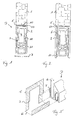
- Figur 1
- eine seitliche Stirnansicht des untersten Teils einer erfindungsgemässen Türe in einer ersten Ausführungsform;
- Figur 2
- die Türe in einer zweiten Ausführungsform;
- Figur 3
- die Türe in einer dritten Ausführungsform;
- Figur 4
- die Türe in einer vierten Ausführungsform;
- Figur 5
- eine Ansicht des untersten Teils einer Türe gemäss dem Stand der Technik mit einer visualisierten Dichtungsfläche;
- Figur 6
- eine Ansicht des untersten Teils einer Türe gemäss der Erfindung mit einer visualisierten Dichtungsfläche und
- Figur 7
- eine seitliche Stirnansicht des untersten Teils einer erfindungsgemässen Türe in einer fünften Ausführungsform.
- 1
- Türflügel
- 10
- untere Stirnfläche
- 11
- Türfläche
- D
- Absenkbare Dichtung
- 2
- Führungsprofil
- 20
- Auflagefläche
- 3
- Dichtleiste
- 30
- Trägerprofil
- 31
- Elastomeres Dichtungsprofil
- 32
- Untere Lippe
- 4
- Absenkmechanismus
- 5
- Klebstoff
- 6
- Aufnahmeprofil
- 60
- Absatz
- 61
- Auflagefläche
- 62
- Winkelelement
- 63
- Anschlagfläche
- 64
- Unterer Schenkel
- B
- Boden
- P
- Profilschiene
- G
- Glasscheibe
- F
- vertikale Dichtungsfläche
- S
- Stufe
- H
- Abstand der Dichtungsfläche
- A
- Länge des unteren Schenkels
Claims (12)
- Schwellenlose Türe mit mindestens einem Türflügel (1) und mit einer absenkbaren Dichtung (D) zum Abdichten des Türflügels (1) im geschlossenen Zustand der Tür, vorzugsweise zum Abdichten nach unten, wobei die Dichtung (D) ein nach unten offenes Führungsprofil (2) und eine im Führungsprofil (2) verschiebbare Dichtleiste (3) aufweist, wobei die Dichtleiste (3) ein Trägerprofil (30) und ein an diesem befestigtes elastomeres Dichtungsprofil (31) umfasst und wobei das Dichtungsprofil (31) im abgesenkten Zustand am Boden (B) anliegt, dadurch gekennzeichnet, dass die absenkbare Dichtung (D) unterhalb einer, vorzugsweise der unteren Stirnfläche (10) des Türflügels (1) angeordnet ist und dass sie an ihrem oberen Ende eine Auflagefläche (20,61) aufweist, welche über eine stoffschlüssige Verbindung mit der Stirnfläche (10) des Türflügels (1) verbunden ist.
- Türe nach Anspruch 1, dadurch gekennzeichnet, dass das Führungsprofil (2) in einem Aufnahmeprofil (6) gehalten ist, welches mit der Stirnfläche (10) des Türflügels (1) verbunden ist.
- Türe nach Anspruch 1, dadurch gekennzeichnet, dass das Führungsprofil (2) mit der Stirnfläche (10) des Türflügels (1) verbunden ist.
- Türe nach einem der Ansprüche 1 bis 3, dadurch gekennzeichnet, dass die Auflagefläche (20,61) mit der Stirnfläche (10) verklebt ist.
- Türe nach Anspruch 1, dadurch gekennzeichnet, dass der Türflügel (1) aus Glas gefertigt ist und die absenkbare Dichtung (D) mit dem Glas stoffschlüssig verbunden ist.
- Türe nach einem der Ansprüche 1 bis 3, dadurch gekennzeichnet, dass mindestens eine vertikale Seite der absenkbaren Dichtung (D) mit einer Fläche des Türflügels (1) fluchtet.
- Türe nach einem der Ansprüche 1 bis 3, dadurch gekennzeichnet, dass zwei gegenüberliegende vertikalen Seiten der absenkbaren Dichtung (D) mit Flächen des Türflügels (1) fluchten.
- Türe nach einem der Ansprüche 1 bis 3, dadurch gekennzeichnet, dass eine vertikale Seite der absenkbaren Dichtung (D) einer Fläche (11) des Türflügels (1) vorsteht.
- Türe nach den Ansprüchen 2 und 8, dadurch gekennzeichnet, dass am oberen Ende der Dichtung (D) ein Winkelelement (62) angeformt ist, wobei ein erster Schenkel des Winkelelementes (62) die Auflagefläche (61) und ein zweiter Schenkel des Winkelelementes (62) eine Anschlagfläche (63) bildet und dass die Anschlagfläche (63) mit einer Fläche (11) des Türflügels (1) verklebt ist.
- Türe nach Anspruch 9, dadurch gekennzeichnet, dass der zweite Schenkel kürzer oder gleich lang ist wie der erste Schenkel.
- Türe nach einem der Ansprüche 1 bis 10, dadurch gekennzeichnet, dass eine untere Stirnfläche des Führungsprofils (2) oder eines Aufnahmeprofils (6) eine Unterseite des Dichtungsprofils (31) in dessen angehobenen Zustand überragt.
- Absenkbare Türdichtung, mit einem nach unten offenen Führungsprofil (2) und einer im Führungsprofil (2) verschiebbaren Dichtleiste (3), wobei die Dichtleiste (3) ein Trägerprofil (30) und ein an diesem befestigtes elastomeres Dichtungsprofil (31) umfasst und wobei das Dichtungsprofil (31) im abgesenkten Zustand am Boden (B) anliegt, dadurch gekennzeichnet, dass eine untere Stirnfläche des Führungsprofils (2) oder eines Aufnahmeprofils (6), in welchem das Führungsprofil (2) gehalten ist, eine Unterseite des Dichtungsprofils (31) in dessen angehobenen Zustand überragt.
Priority Applications (1)
| Application Number | Priority Date | Filing Date | Title |
|---|---|---|---|
| EP07005141.2A EP1790816B1 (de) | 2001-07-20 | 2002-04-22 | Schwellenlose glastür mit absenkbarer dichtung |
Applications Claiming Priority (2)
| Application Number | Priority Date | Filing Date | Title |
|---|---|---|---|
| CH01346/01A CH702691B1 (de) | 2001-07-20 | 2001-07-20 | Schwellenlose Türe mit mindestens einem Türflügel und mit einer absenkbaren Dichtung . |
| CH13462001 | 2001-07-20 |
Related Child Applications (1)
| Application Number | Title | Priority Date | Filing Date |
|---|---|---|---|
| EP07005141.2A Division EP1790816B1 (de) | 2001-07-20 | 2002-04-22 | Schwellenlose glastür mit absenkbarer dichtung |
Publications (2)
| Publication Number | Publication Date |
|---|---|
| EP1277910A1 true EP1277910A1 (de) | 2003-01-22 |
| EP1277910B1 EP1277910B1 (de) | 2009-08-19 |
Family
ID=4565398
Family Applications (2)
| Application Number | Title | Priority Date | Filing Date |
|---|---|---|---|
| EP07005141.2A Expired - Lifetime EP1790816B1 (de) | 2001-07-20 | 2002-04-22 | Schwellenlose glastür mit absenkbarer dichtung |
| EP02405324A Expired - Lifetime EP1277910B1 (de) | 2001-07-20 | 2002-04-22 | Schwellenlose Türe mit absenkbarer Dichtung |
Family Applications Before (1)
| Application Number | Title | Priority Date | Filing Date |
|---|---|---|---|
| EP07005141.2A Expired - Lifetime EP1790816B1 (de) | 2001-07-20 | 2002-04-22 | Schwellenlose glastür mit absenkbarer dichtung |
Country Status (4)
| Country | Link |
|---|---|
| EP (2) | EP1790816B1 (de) |
| AT (1) | ATE440204T1 (de) |
| CH (1) | CH702691B1 (de) |
| DE (1) | DE50213777D1 (de) |
Cited By (3)
| Publication number | Priority date | Publication date | Assignee | Title |
|---|---|---|---|---|
| DE202005021765U1 (de) | 2004-09-07 | 2009-12-17 | Planet Gdz Ag | Türdichtung |
| EP2824271A1 (de) | 2013-07-08 | 2015-01-14 | Planet GDZ AG | Türdichtungssystem |
| DE202023106338U1 (de) | 2023-10-31 | 2025-02-10 | Assa Abloy (Schweiz) Ag | Dichtungseinheit |
Families Citing this family (1)
| Publication number | Priority date | Publication date | Assignee | Title |
|---|---|---|---|---|
| EP3112577B1 (de) * | 2015-07-01 | 2017-08-30 | Planet GDZ AG | Absenkdichtung |
Citations (4)
| Publication number | Priority date | Publication date | Assignee | Title |
|---|---|---|---|---|
| DE1181389B (de) * | 1959-07-22 | 1964-11-12 | Athmer Fa F | Abdichtungsvorrichtung fuer Tueren |
| US4425738A (en) * | 1982-11-24 | 1984-01-17 | Christensen Curtis M | Automatic threshold seal for a door |
| US4805345A (en) * | 1987-07-10 | 1989-02-21 | Nankai Kogyo Kabushiki Kaisha | Sealing device for a door |
| EP0609755A1 (de) * | 1993-01-29 | 1994-08-10 | Firma F. Athmer | Bodenseitige Dichtungsvorrichtung für eine Tür |
Family Cites Families (6)
| Publication number | Priority date | Publication date | Assignee | Title |
|---|---|---|---|---|
| US4519165A (en) * | 1984-01-05 | 1985-05-28 | F. Athmer | Sealing device for the bottom of a door |
| US4712331A (en) * | 1984-12-26 | 1987-12-15 | Hardglass Industry Co., Ltd. | Door |
| FI88332C (fi) | 1988-04-19 | 1993-04-26 | Planet Matthias Jaggi | Taetningsanordning foer en troeskelloes doerr |
| CH688741A5 (de) | 1994-06-01 | 1998-02-13 | Matthias Jaggi | Dichtungsvorrichtung, insbesondere für Türflügel. |
| DE19700886A1 (de) * | 1997-01-14 | 1998-07-16 | Dorma Gmbh & Co Kg | Duschabtrennung |
| DE20002108U1 (de) | 2000-02-07 | 2000-04-20 | PLANET GDZ AG, Nürensdorf | Türflügel für eine schwellenlose Türe |
-
2001
- 2001-07-20 CH CH01346/01A patent/CH702691B1/de not_active IP Right Cessation
-
2002
- 2002-04-22 AT AT02405324T patent/ATE440204T1/de not_active IP Right Cessation
- 2002-04-22 EP EP07005141.2A patent/EP1790816B1/de not_active Expired - Lifetime
- 2002-04-22 EP EP02405324A patent/EP1277910B1/de not_active Expired - Lifetime
- 2002-04-22 DE DE50213777T patent/DE50213777D1/de not_active Expired - Lifetime
Patent Citations (4)
| Publication number | Priority date | Publication date | Assignee | Title |
|---|---|---|---|---|
| DE1181389B (de) * | 1959-07-22 | 1964-11-12 | Athmer Fa F | Abdichtungsvorrichtung fuer Tueren |
| US4425738A (en) * | 1982-11-24 | 1984-01-17 | Christensen Curtis M | Automatic threshold seal for a door |
| US4805345A (en) * | 1987-07-10 | 1989-02-21 | Nankai Kogyo Kabushiki Kaisha | Sealing device for a door |
| EP0609755A1 (de) * | 1993-01-29 | 1994-08-10 | Firma F. Athmer | Bodenseitige Dichtungsvorrichtung für eine Tür |
Cited By (5)
| Publication number | Priority date | Publication date | Assignee | Title |
|---|---|---|---|---|
| DE202005021765U1 (de) | 2004-09-07 | 2009-12-17 | Planet Gdz Ag | Türdichtung |
| EP2824271A1 (de) | 2013-07-08 | 2015-01-14 | Planet GDZ AG | Türdichtungssystem |
| WO2015003942A1 (de) | 2013-07-08 | 2015-01-15 | Planet Gdz Ag | Türdichtungssystem |
| DE202023106338U1 (de) | 2023-10-31 | 2025-02-10 | Assa Abloy (Schweiz) Ag | Dichtungseinheit |
| EP4549692A1 (de) | 2023-10-31 | 2025-05-07 | ASSA ABLOY (Schweiz) AG | Dichtungseinheit |
Also Published As
| Publication number | Publication date |
|---|---|
| ATE440204T1 (de) | 2009-09-15 |
| EP1790816B1 (de) | 2020-02-26 |
| EP1790816A2 (de) | 2007-05-30 |
| DE50213777D1 (de) | 2009-10-01 |
| EP1790816A3 (de) | 2013-02-27 |
| CH702691B1 (de) | 2011-08-31 |
| HK1051885A1 (zh) | 2003-08-22 |
| EP1277910B1 (de) | 2009-08-19 |
Similar Documents
| Publication | Publication Date | Title |
|---|---|---|
| DE10329518B4 (de) | Führungseinrichtung für eine Schiebetür | |
| DE3705433A1 (de) | Duschabtrennung mit einem drehfluegel | |
| DE19733367A1 (de) | Flügel für eine Tür, ein Fenster oder dergleichen | |
| DE19926955B4 (de) | Stegkappe aus gummielastischem Material | |
| EP0819816B1 (de) | Türschwellenprofil | |
| EP0347537B1 (de) | Fahrzeugtür mit Fensterrahmen | |
| DE19730600A1 (de) | Stulpschienenbeschlag | |
| EP1308590B2 (de) | Kantriegel für eine Tür | |
| EP1439278A2 (de) | Dichtung, insbesondere Auflaufdichtung oder sich selbsttätig absenkende Bodendichtung für Türen mit einstellbarer Befestigung | |
| EP1277910B1 (de) | Schwellenlose Türe mit absenkbarer Dichtung | |
| EP1498569B1 (de) | Türdichtung | |
| EP0784144A1 (de) | Magnetische Türdichtung und Zusatzprofile zu deren Herstellung | |
| EP1718835A1 (de) | Befestigunsvorrichtung für eine gleit- oder führungsschiene | |
| EP1447514B1 (de) | Absenkbare Türdichtung einer Schiebetür | |
| EP1279791B1 (de) | Absenkbare Türdichtung | |
| EP0524631A1 (de) | Halteglied für Isolierglasscheiben | |
| EP0408871A2 (de) | Dichtung am Mittelstoss von Fenstern oder Türen mit horizontal verschiebbaren Flügeln | |
| EP4534793B1 (de) | Tür- oder fensteranordnung | |
| EP1072751A2 (de) | Tür mit Bodendichtung | |
| DE20221112U1 (de) | Schwellenlose Tür mit absenkbarer Dichtung | |
| EP1025790B1 (de) | Duschabtrennung | |
| EP3674509B1 (de) | Abschlusselement | |
| EP0736436B1 (de) | Schienenfahrzeug | |
| DE8615696U1 (de) | Strangartiges Dichtungsprofil | |
| DE202025103742U1 (de) | Türanordnung |
Legal Events
| Date | Code | Title | Description |
|---|---|---|---|
| PUAI | Public reference made under article 153(3) epc to a published international application that has entered the european phase |
Free format text: ORIGINAL CODE: 0009012 |
|
| AK | Designated contracting states |
Kind code of ref document: A1 Designated state(s): AT BE CH CY DE DK ES FI FR GB GR IE IT LI LU MC NL PT SE TR |
|
| AX | Request for extension of the european patent |
Free format text: AL;LT;LV;MK;RO;SI |
|
| 17P | Request for examination filed |
Effective date: 20030426 |
|
| AKX | Designation fees paid |
Designated state(s): AT BE CH CY DE DK ES FI FR GB GR IE IT LI LU MC NL PT SE TR |
|
| AXX | Extension fees paid |
Extension state: LT Payment date: 20030426 Extension state: SI Payment date: 20030426 Extension state: LV Payment date: 20030426 |
|
| 17Q | First examination report despatched |
Effective date: 20041207 |
|
| 17Q | First examination report despatched |
Effective date: 20041207 |
|
| RAP1 | Party data changed (applicant data changed or rights of an application transferred) |
Owner name: PLANET GDZ AG |
|
| RAP1 | Party data changed (applicant data changed or rights of an application transferred) |
Owner name: PLANET GDZ AG |
|
| GRAP | Despatch of communication of intention to grant a patent |
Free format text: ORIGINAL CODE: EPIDOSNIGR1 |
|
| GRAS | Grant fee paid |
Free format text: ORIGINAL CODE: EPIDOSNIGR3 |
|
| GRAA | (expected) grant |
Free format text: ORIGINAL CODE: 0009210 |
|
| AK | Designated contracting states |
Kind code of ref document: B1 Designated state(s): AT BE CH CY DE DK ES FI FR GB GR IE IT LI LU MC NL PT SE TR |
|
| AX | Request for extension of the european patent |
Extension state: LT LV SI |
|
| REG | Reference to a national code |
Ref country code: GB Ref legal event code: FG4D Free format text: NOT ENGLISH |
|
| REG | Reference to a national code |
Ref country code: CH Ref legal event code: EP |
|
| REG | Reference to a national code |
Ref country code: IE Ref legal event code: FG4D |
|
| REG | Reference to a national code |
Ref country code: CH Ref legal event code: NV Representative=s name: ISLER & PEDRAZZINI AG |
|
| REF | Corresponds to: |
Ref document number: 50213777 Country of ref document: DE Date of ref document: 20091001 Kind code of ref document: P |
|
| LTIE | Lt: invalidation of european patent or patent extension |
Effective date: 20090819 |
|
| PG25 | Lapsed in a contracting state [announced via postgrant information from national office to epo] |
Ref country code: ES Free format text: LAPSE BECAUSE OF FAILURE TO SUBMIT A TRANSLATION OF THE DESCRIPTION OR TO PAY THE FEE WITHIN THE PRESCRIBED TIME-LIMIT Effective date: 20091130 Ref country code: FI Free format text: LAPSE BECAUSE OF FAILURE TO SUBMIT A TRANSLATION OF THE DESCRIPTION OR TO PAY THE FEE WITHIN THE PRESCRIBED TIME-LIMIT Effective date: 20090819 Ref country code: SE Free format text: LAPSE BECAUSE OF FAILURE TO SUBMIT A TRANSLATION OF THE DESCRIPTION OR TO PAY THE FEE WITHIN THE PRESCRIBED TIME-LIMIT Effective date: 20090819 |
|
| REG | Reference to a national code |
Ref country code: HK Ref legal event code: GR Ref document number: 1051885 Country of ref document: HK |
|
| REG | Reference to a national code |
Ref country code: IE Ref legal event code: FD4D |
|
| PG25 | Lapsed in a contracting state [announced via postgrant information from national office to epo] |
Ref country code: CY Free format text: LAPSE BECAUSE OF FAILURE TO SUBMIT A TRANSLATION OF THE DESCRIPTION OR TO PAY THE FEE WITHIN THE PRESCRIBED TIME-LIMIT Effective date: 20090819 Ref country code: PT Free format text: LAPSE BECAUSE OF FAILURE TO SUBMIT A TRANSLATION OF THE DESCRIPTION OR TO PAY THE FEE WITHIN THE PRESCRIBED TIME-LIMIT Effective date: 20091221 |
|
| PG25 | Lapsed in a contracting state [announced via postgrant information from national office to epo] |
Ref country code: DK Free format text: LAPSE BECAUSE OF FAILURE TO SUBMIT A TRANSLATION OF THE DESCRIPTION OR TO PAY THE FEE WITHIN THE PRESCRIBED TIME-LIMIT Effective date: 20090819 Ref country code: IE Free format text: LAPSE BECAUSE OF FAILURE TO SUBMIT A TRANSLATION OF THE DESCRIPTION OR TO PAY THE FEE WITHIN THE PRESCRIBED TIME-LIMIT Effective date: 20090819 |
|
| PLBE | No opposition filed within time limit |
Free format text: ORIGINAL CODE: 0009261 |
|
| STAA | Information on the status of an ep patent application or granted ep patent |
Free format text: STATUS: NO OPPOSITION FILED WITHIN TIME LIMIT |
|
| 26N | No opposition filed |
Effective date: 20100520 |
|
| PG25 | Lapsed in a contracting state [announced via postgrant information from national office to epo] |
Ref country code: GR Free format text: LAPSE BECAUSE OF FAILURE TO SUBMIT A TRANSLATION OF THE DESCRIPTION OR TO PAY THE FEE WITHIN THE PRESCRIBED TIME-LIMIT Effective date: 20091120 |
|
| BERE | Be: lapsed |
Owner name: PLANET GDZ A.G. Effective date: 20100430 |
|
| PG25 | Lapsed in a contracting state [announced via postgrant information from national office to epo] |
Ref country code: MC Free format text: LAPSE BECAUSE OF NON-PAYMENT OF DUE FEES Effective date: 20100430 |
|
| GBPC | Gb: european patent ceased through non-payment of renewal fee |
Effective date: 20100422 |
|
| REG | Reference to a national code |
Ref country code: FR Ref legal event code: ST Effective date: 20101230 |
|
| PG25 | Lapsed in a contracting state [announced via postgrant information from national office to epo] |
Ref country code: BE Free format text: LAPSE BECAUSE OF NON-PAYMENT OF DUE FEES Effective date: 20100430 Ref country code: GB Free format text: LAPSE BECAUSE OF NON-PAYMENT OF DUE FEES Effective date: 20100422 |
|
| PG25 | Lapsed in a contracting state [announced via postgrant information from national office to epo] |
Ref country code: AT Free format text: LAPSE BECAUSE OF NON-PAYMENT OF DUE FEES Effective date: 20100422 |
|
| PG25 | Lapsed in a contracting state [announced via postgrant information from national office to epo] |
Ref country code: FR Free format text: LAPSE BECAUSE OF NON-PAYMENT OF DUE FEES Effective date: 20100430 |
|
| PG25 | Lapsed in a contracting state [announced via postgrant information from national office to epo] |
Ref country code: LU Free format text: LAPSE BECAUSE OF NON-PAYMENT OF DUE FEES Effective date: 20100422 |
|
| PG25 | Lapsed in a contracting state [announced via postgrant information from national office to epo] |
Ref country code: TR Free format text: LAPSE BECAUSE OF FAILURE TO SUBMIT A TRANSLATION OF THE DESCRIPTION OR TO PAY THE FEE WITHIN THE PRESCRIBED TIME-LIMIT Effective date: 20090819 |
|
| PGFP | Annual fee paid to national office [announced via postgrant information from national office to epo] |
Ref country code: NL Payment date: 20190418 Year of fee payment: 18 |
|
| PGFP | Annual fee paid to national office [announced via postgrant information from national office to epo] |
Ref country code: CH Payment date: 20190410 Year of fee payment: 18 |
|
| PGFP | Annual fee paid to national office [announced via postgrant information from national office to epo] |
Ref country code: DE Payment date: 20200408 Year of fee payment: 19 |
|
| PGFP | Annual fee paid to national office [announced via postgrant information from national office to epo] |
Ref country code: IT Payment date: 20200312 Year of fee payment: 19 |
|
| REG | Reference to a national code |
Ref country code: CH Ref legal event code: PL |
|
| REG | Reference to a national code |
Ref country code: NL Ref legal event code: MM Effective date: 20200501 |
|
| PG25 | Lapsed in a contracting state [announced via postgrant information from national office to epo] |
Ref country code: CH Free format text: LAPSE BECAUSE OF NON-PAYMENT OF DUE FEES Effective date: 20200430 Ref country code: LI Free format text: LAPSE BECAUSE OF NON-PAYMENT OF DUE FEES Effective date: 20200430 |
|
| PG25 | Lapsed in a contracting state [announced via postgrant information from national office to epo] |
Ref country code: NL Free format text: LAPSE BECAUSE OF NON-PAYMENT OF DUE FEES Effective date: 20200501 |
|
| REG | Reference to a national code |
Ref country code: DE Ref legal event code: R119 Ref document number: 50213777 Country of ref document: DE |
|
| PG25 | Lapsed in a contracting state [announced via postgrant information from national office to epo] |
Ref country code: DE Free format text: LAPSE BECAUSE OF NON-PAYMENT OF DUE FEES Effective date: 20211103 |
|
| PG25 | Lapsed in a contracting state [announced via postgrant information from national office to epo] |
Ref country code: IT Free format text: LAPSE BECAUSE OF NON-PAYMENT OF DUE FEES Effective date: 20200422 |
|
| PG25 | Lapsed in a contracting state [announced via postgrant information from national office to epo] |
Ref country code: IT Free format text: LAPSE BECAUSE OF NON-PAYMENT OF DUE FEES Effective date: 20210422 |