EP1278008A2 - Boítier de luminaire - Google Patents
Boítier de luminaire Download PDFInfo
- Publication number
- EP1278008A2 EP1278008A2 EP02014975A EP02014975A EP1278008A2 EP 1278008 A2 EP1278008 A2 EP 1278008A2 EP 02014975 A EP02014975 A EP 02014975A EP 02014975 A EP02014975 A EP 02014975A EP 1278008 A2 EP1278008 A2 EP 1278008A2
- Authority
- EP
- European Patent Office
- Prior art keywords
- holding frame
- housing part
- cover body
- cover plate
- fastening means
- Prior art date
- Legal status (The legal status is an assumption and is not a legal conclusion. Google has not performed a legal analysis and makes no representation as to the accuracy of the status listed.)
- Withdrawn
Links
- 230000033001 locomotion Effects 0.000 claims abstract description 49
- 230000002093 peripheral effect Effects 0.000 claims description 18
- 239000011521 glass Substances 0.000 claims description 15
- 230000007246 mechanism Effects 0.000 claims description 11
- 229920003023 plastic Polymers 0.000 claims description 8
- 230000000694 effects Effects 0.000 claims description 5
- 239000004033 plastic Substances 0.000 description 5
- 239000002313 adhesive film Substances 0.000 description 4
- 230000008901 benefit Effects 0.000 description 3
- 238000003780 insertion Methods 0.000 description 3
- 230000037431 insertion Effects 0.000 description 3
- 238000009434 installation Methods 0.000 description 3
- 239000002184 metal Substances 0.000 description 3
- 229910052751 metal Inorganic materials 0.000 description 3
- UQSXHKLRYXJYBZ-UHFFFAOYSA-N Iron oxide Chemical compound [Fe]=O UQSXHKLRYXJYBZ-UHFFFAOYSA-N 0.000 description 2
- 239000000853 adhesive Substances 0.000 description 2
- 230000001070 adhesive effect Effects 0.000 description 2
- 239000011324 bead Substances 0.000 description 2
- 230000009286 beneficial effect Effects 0.000 description 2
- 239000002131 composite material Substances 0.000 description 2
- 230000004313 glare Effects 0.000 description 2
- 238000004519 manufacturing process Methods 0.000 description 2
- 239000000463 material Substances 0.000 description 2
- 239000011022 opal Substances 0.000 description 2
- 238000003825 pressing Methods 0.000 description 2
- 230000009467 reduction Effects 0.000 description 2
- 239000005336 safety glass Substances 0.000 description 2
- 241000190070 Sarracenia purpurea Species 0.000 description 1
- NIXOWILDQLNWCW-UHFFFAOYSA-N acrylic acid group Chemical group C(C=C)(=O)O NIXOWILDQLNWCW-UHFFFAOYSA-N 0.000 description 1
- 238000004026 adhesive bonding Methods 0.000 description 1
- 230000032683 aging Effects 0.000 description 1
- 238000005422 blasting Methods 0.000 description 1
- 230000008859 change Effects 0.000 description 1
- 238000004040 coloring Methods 0.000 description 1
- 230000006835 compression Effects 0.000 description 1
- 238000007906 compression Methods 0.000 description 1
- 238000010276 construction Methods 0.000 description 1
- 239000006059 cover glass Substances 0.000 description 1
- 230000001419 dependent effect Effects 0.000 description 1
- 238000005530 etching Methods 0.000 description 1
- 238000001914 filtration Methods 0.000 description 1
- 239000011888 foil Substances 0.000 description 1
- 238000007373 indentation Methods 0.000 description 1
- 230000009191 jumping Effects 0.000 description 1
- 238000000034 method Methods 0.000 description 1
- 239000008267 milk Substances 0.000 description 1
- 210000004080 milk Anatomy 0.000 description 1
- 235000013336 milk Nutrition 0.000 description 1
- 230000008569 process Effects 0.000 description 1
Images


Classifications
-
- F—MECHANICAL ENGINEERING; LIGHTING; HEATING; WEAPONS; BLASTING
- F21—LIGHTING
- F21V—FUNCTIONAL FEATURES OR DETAILS OF LIGHTING DEVICES OR SYSTEMS THEREOF; STRUCTURAL COMBINATIONS OF LIGHTING DEVICES WITH OTHER ARTICLES, NOT OTHERWISE PROVIDED FOR
- F21V17/00—Fastening of component parts of lighting devices, e.g. shades, globes, refractors, reflectors, filters, screens, grids or protective cages
- F21V17/10—Fastening of component parts of lighting devices, e.g. shades, globes, refractors, reflectors, filters, screens, grids or protective cages characterised by specific fastening means or way of fastening
- F21V17/14—Bayonet-type fastening
-
- F—MECHANICAL ENGINEERING; LIGHTING; HEATING; WEAPONS; BLASTING
- F21—LIGHTING
- F21S—NON-PORTABLE LIGHTING DEVICES; SYSTEMS THEREOF; VEHICLE LIGHTING DEVICES SPECIALLY ADAPTED FOR VEHICLE EXTERIORS
- F21S8/00—Lighting devices intended for fixed installation
- F21S8/02—Lighting devices intended for fixed installation of recess-mounted type, e.g. downlighters
-
- F—MECHANICAL ENGINEERING; LIGHTING; HEATING; WEAPONS; BLASTING
- F21—LIGHTING
- F21S—NON-PORTABLE LIGHTING DEVICES; SYSTEMS THEREOF; VEHICLE LIGHTING DEVICES SPECIALLY ADAPTED FOR VEHICLE EXTERIORS
- F21S8/00—Lighting devices intended for fixed installation
- F21S8/03—Lighting devices intended for fixed installation of surface-mounted type
- F21S8/033—Lighting devices intended for fixed installation of surface-mounted type the surface being a wall or like vertical structure, e.g. building facade
-
- F—MECHANICAL ENGINEERING; LIGHTING; HEATING; WEAPONS; BLASTING
- F21—LIGHTING
- F21S—NON-PORTABLE LIGHTING DEVICES; SYSTEMS THEREOF; VEHICLE LIGHTING DEVICES SPECIALLY ADAPTED FOR VEHICLE EXTERIORS
- F21S8/00—Lighting devices intended for fixed installation
- F21S8/04—Lighting devices intended for fixed installation intended only for mounting on a ceiling or the like overhead structures
-
- F—MECHANICAL ENGINEERING; LIGHTING; HEATING; WEAPONS; BLASTING
- F21—LIGHTING
- F21V—FUNCTIONAL FEATURES OR DETAILS OF LIGHTING DEVICES OR SYSTEMS THEREOF; STRUCTURAL COMBINATIONS OF LIGHTING DEVICES WITH OTHER ARTICLES, NOT OTHERWISE PROVIDED FOR
- F21V17/00—Fastening of component parts of lighting devices, e.g. shades, globes, refractors, reflectors, filters, screens, grids or protective cages
- F21V17/10—Fastening of component parts of lighting devices, e.g. shades, globes, refractors, reflectors, filters, screens, grids or protective cages characterised by specific fastening means or way of fastening
- F21V17/18—Latch-type fastening, e.g. with rotary action
Definitions
- the invention relates to a luminaire housing with a housing part and a cover body provided with a holding frame, wherein the holding frame with the housing part can be detached via fastening means connected is.
- Such luminaire housings are in as wall and ceiling lights Form of surface or recessed installations available.
- the cover body which is attached in the lamp housing Illuminant covers, either directly or by means of Holding frame via a screw connection with the housing part connected.
- the screw connection is either through openings guided in the cover body or connects the holding frame laterally with the housing part.
- the cover body is usually in shape a transparent cover plate. Attaching the Openings in a glass cover plate are a complex manufacturing process, which also involves the risk of damage to the cover glass by jumping hides.
- the holding force for the Cover body with such an attachment point to the Openings of the cover body applied, which in particular large ceiling lights to considerable tension in the Cover body leads. Through the openings in the cover body guided screw fastenings do not only influence the design of the lamp housing but form protrusions on the otherwise flat cover plate, where dirt is preferred accumulate.
- Another possibility for fastening the cover body is one lateral attachment of the holding frame to the housing part by means of Screws.
- the implementation of a Screw connection through the cover plate can be dispensed with, however
- Such an arrangement is not suitable for flush mounting of the luminaire housing, since the side screw connections are no longer accessible after installation.
- locking lever for locking between the holding frame and the housing part must be led out of the luminaire housing for actuation and be accessible from the outside. This is particularly so when installing the lamp, e.g. in a plasterboard ceiling, not always possible.
- screw connections Another disadvantage when using screw connections consists in that for screwing or loosening the screw suitable tools, such as screwdrivers or Wrenches, which may be necessary for a Person who changes the lamp in the lamp housing would like to be handled under unfavorable conditions.
- the object of the invention is to provide a luminaire housing which is an easy to use and secure connection between the cover body provided with a holding frame and the Housing part is made possible.
- the lamp housing can be a housing part and have a cover body provided with a holding frame.
- the housing part can be used to mount the lamp, for example can be attached to a ceiling or wall.
- the cover body can be an arbitrarily shaped and / or transparent body, for example in the form of a hemisphere or a plate that a covers the lamp attached to the lamp housing.
- the basic shape of the lamp housing can be any, preferred however, are rectangular, triangular or n-angular shapes as well round housing shapes used.
- the holding frame can be made essentially of the same material like the cover body. Holding frame and cover body can also be designed as a common part. The holding frame but can also be made of a different material than the cover body exist, for example, metal or plastic are special suitable.
- the holding frame can also consist of several together connected, e.g. screwed or glued parts.
- the holding frame can for example be on the side or on the Be back of the cover body attached. It is beneficial if the holding frame the outer boundary of the cover body forms and the peripheral surface of the cover body or its outer Edge encloses.
- the holding frame can be attached to the housing part using fasteners be releasably connected, the fastening means a Ver and Unlocking the holding frame with the housing part by a linear Movement of the holding frame and the housing part relative effect each other.
- This linear movement takes place along one Axis, which is preferably perpendicular to the base of the housing part stands.
- By moving the holding frame and the housing part relative to each other the holding frame and the housing part locked together. By another similar movement both can be unlocked again.
- This principle enables an easy to use detachable connection of the Holding frame with the housing part without the use of Tools.
- the light housing can be replaced by a light Pressure on the cover body to replace the lamp opened and then closed again. A cumbersome Handling a screwdriver or wrench to tighten or loosen a screw connection is at the luminaire housing according to the invention is not necessary.
- the fasteners can be used as suitable spring snap locks be formed, the one and one by the linear movement Snap out and thus lock and unlock the holding frame effect with the housing part.
- the cover body is a cover plate educated.
- the axis of the linear movement then stands perpendicular to the outer surface of the cover plate.
- the locking and unlocking the fastening means can be affected by a force (e.g. by pressing) on the cover body and / or the holding frame in the direction of the housing part.
- the connection between Cover body and holding frame with the housing part can through solved a simple force on the cover body and again be locked.
- the cover body as a cover plate is formed, the locking and unlocking of the fasteners done particularly easily.
- pressing the cover plate exerts a force in the direction of the housing part, the perpendicular to the outer surface of the cover plate and is parallel to the axis of the associated linear movement.
- the releasable fasteners snap due to the force on and off and enable an easy to use and safe Connection of the holding frame to the housing part.
- the Fasteners one or more levers.
- the lever can be designed to be pivotable or linearly movable. Caused by the linear movement of the holding frame and / or due to the force, the lever or levers lock into a bulge and are locked in this position.
- a spring mechanism in the fastening means is preferred used, which snaps and the lever in the locked position fixed.
- the fastening means can preferably be attached to the housing part be and the lever in a bulge of the holding frame intervention. It is of course also possible to use the fasteners to attach to the holding frame, with the levers in a suitable bulge of the housing part can intervene.
- the lever on the bulge engaging end have a roller, a wheel or a ball, so that the friction between the lever and bulge when moving and Unlocking is reduced and smooth movement is achieved.
- the holding frame arranged within the housing part and is by this guided.
- the housing part thus forms the outer end of the Luminaire housing and protects the holding frame and the cover body from damage.
- the fastening means are expediently located within the housing part appropriate. This allows a particularly simple one Structure of the lamp housing and a reduction in weight of the holding frame.
- the pivotable lever or fasteners can engage in a bulge in the holding frame, to keep it in the locked position.
- the bulge the holding frame is advantageously designed such that the pivoting lever, caused by the linear movement of the Holding frame and the housing part relative to each other, operated becomes.
- the pivotable lever By actuation, the pivotable lever is in the locking position brought and locked there.
- the locked lever prevents the holding frame from falling out and the cover body from the housing part.
- the pivoting lever is moved by a linear movement of the Holding frame in the direction of the housing part or a corresponding one Force on the cover body in the locking position brought.
- the fasteners can absorb forces acting on the Act holding frame in a direction away from the housing part. The The holding frame with the cover body is held in this position.
- the fastening means one or more pins to lock the Holding frame with the housing part in one or more bulges intervention.
- the retaining pins can, for example, by spring force operated and held in the engaged position.
- the appropriate bulge can be on the housing part as well be provided on the holding frame.
- the one or more holding pins and the The spring mechanism is on the holding frame or on Housing part attached.
- the spring mechanism can have a compression spring, for example, the presses against the retaining pins to keep them in the locked position to keep in the bulge.
- the locking and unlocking takes place by a linear movement of the holding frame and the housing part relative to each other along an axis.
- the Fasteners one or more pivotable levers on the engage with one or more pins for locking and by a spring mechanism in a locking position can be locked.
- the lever can have a bulge have, in which the pin engages in the locking position and firmly connects the holding frame and the housing part to one another.
- the pin can be on the holding frame and the pivoting lever be attached to the housing part or vice versa.
- the spring mechanism expediently has a spring on the lever acts. To close the lamp, the pin comes with the Lever in contact and moves it into the locked position, in which are both firmly connected.
- the lever can be in the Locking position can be held by a stop.
- Unlocking the holding frame and the housing part can be locked of the lever by another linear movement that the lever can be moved from the locking position, released, and the holding frame with cover body can be removed. It is beneficial the lever by the spring and another stop in the unlocked Hold position for easy insertion of the lamp to enable.
- the holding frame covered on a peripheral surface of the cover body or the Cover plate attached.
- the holding frame can, for example, with glued to the peripheral surface or otherwise connected to it his.
- By attaching the holding frame to the side the cover body or the cover plate can have their side faces or peripheral surfaces are protected from damage.
- the lateral covering of the cover body can be done by a corresponding Design of the holding frame completely or partially respectively. Due to the concealed attachment of the invention Holding frame is the entire cover body in a plan view or the entire surface of the cover plate is visible. So it can Possibly disruptive effects due to parts visible in the top view the holding frame or by visible fasteners, for example Cover parts of the cover plate, largely avoided become.
- the holding frame engages in a recess in the peripheral surface of the cover body on.
- a simple attachment of the Holding frame can be achieved on the cover body.
- the holding frame on the Attaching the cover plate engages a projection of the holding frame into a circumferential groove in the peripheral surface of the cover plate.
- a to the peripheral surface of the cover plate all-round holding frame can be attached easily and securely.
- the holding force for the cover plate is in such an embodiment distributed along the peripheral surface of the cover plate what is of great advantage especially in the case of glass-like cover plates.
- the holding frame is even with the holding force for the Cover plate loaded.
- the holding frame can have one or more projections have, with which he in one or more wells in engages the peripheral surface of the cover body. It is special advantageous, the projections and the corresponding recesses to be arranged uniformly along the circumferential surface of the cover body, the force with which the holding frame holds the cover body keeps distributing evenly.
- the cover body can also have a chamfer into which the protrusion of the holding frame engages to hold the cover body.
- the chamfer can be circumferential or on parts of the peripheral surface of the Cover body may be provided.
- a chamfer on the edge of a disc is particularly easy to manufacture, especially for cover plates made of glass or plastic.
- the cover plate can have several adhesively bonded to one another Have panes, for example a security network, similar to a laminated safety glass.
- Have panes for example a security network, similar to a laminated safety glass.
- Gluing multiple panes can change their properties advantageously combined with each other, for example, a To achieve tint or a reduction in weight of the cover plate.
- the cover plate can be designed as a vacuum composite.
- a or several recesses in the peripheral surface of the cover plate arise.
- One or more projections can be placed in these recesses of the holding frame.
- three discs with a round, oval or square base glued together. If the footprint the middle of the three disks is smaller than the base of the outer one is a circumferential groove in the two disks Circumferential surface of the cover plate into which the protrusion of the holding frame can intervene.
- each other another appropriate arrangement to be glued with one or more recesses in the peripheral surface of the cover plate to achieve.
- the discs can also be used on others Wise without being glued to one another get connected.
- the adhesive film can consist of PVB, for example. It is also useful to have an adhesive film with high resistance to be used against temperature, humidity and light to prevent aging of the adhesive connection.
- a suitable foil arranged between the panes can be further advantageous effects, such as coloring or filtering of the light passing through can be achieved.
- a matt film is placed between the panes his.
- the cover body or the cover plate must be matted. With such a matting can still cover the illuminant and a glare can be reduced by the lamp.
- a particularly even matting of the cover body or the cover plate can be etched or glass bead blasted respectively. It is particularly useful if an inside Surface of one of the glued panes matted or with a Opal layer is provided. Such a cover plate made of glass An opal layer on the back is also used as a milk overlay glass designated. In a further embodiment of the invention also an external surface of the cover plate is matted his.
- the cover body or the cover plate can advantageously be made of glass or plastic.
- glass is low in iron oxide or transparent plastic.
- the cover plate also be designed as a perforated plate.
- a light source carrier is expedient in the interior of the housing part attached to accommodate a lamp.
- the invention Luminaire housing can be used with a variety of known Bulbs of different shapes and different Luminosity.
- the supply of the power supply for the lamp for example, through an opening in the Rear wall of the housing part.
- the Fastening a locking and unlocking of the holding frame with the housing part by a rotary movement and / or a linear Movement of the holding frame and the housing part relative to each other.
- levers or pins are brought into a locking position, in which they engage in one or more bulges and be locked in this position.
- the locking can be done by a further movement, preferably with a sense of rotation the first rotary movement, unlocked and the connection between Retaining frame and housing part are released.
- a locking and unlocking by a rotary movement is especially for luminaire housings advantageous with a round base.
- the levers and / or Pins can be locked and / or spring mechanism the fasteners are held in the locked position.
- a projection of the holding frame expediently engages in one Indentation in the peripheral surface of the cover body to a concealed fastening of the holding frame with the cover body create.
- the depression is advantageously in the form of a circumferential groove formed the peripheral surface of the cover body.
- the cover body can be used as a transparent cover plate, for example made of glass or translucent plastic.
- the fastening means are designed as a bayonet catch.
- the fasteners can have a pin that is rotated into a appropriately trained bulge engages and thus the Holding frame connects to the housing part.
- the pen or pens are either attached to the housing part and engage in a bulge of the holding frame or they are attached to the holding frame and engage in a corresponding bulge in the housing part on.
- a bayonet lock simply a durable and detachable connection between the holding frame and housing part can be achieved, especially for luminaire housings with a round basic shape is appropriate.
- the lamp housing according to the invention has fastening means for locking and unlocking the holding frame with the housing part with a simple and secure connection of the holding frame enable the housing part. Opening and closing the Luminaire housing is without the aid of tools and Tools by a linear movement or a rotary movement the holding frame and the housing part relative to each other or a appropriate force possible.
- Training of the lamp housing can both in assembled and operated in a body and in an installation position become. Due to the arrangement of the holding frame according to the invention can this with the cover body without screw fastenings or additional parts can be detachably connected.
- Through the concealed bracket of the, for example, formed as a cover plate Cover body the entire cover surface is visible. The Engagement of the holding frame in a circumferential groove in the peripheral surface of the cover body distributes the force with which the holding frame holds the cover body evenly on the cover body and allows large and / or heavy cover bodies to be securely to keep.
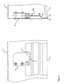
- Fig. 1 shows three different views of an inventive Luminaire housing, with a top view of an open one in the middle Luminaire housing and two different side views above and left of a closed luminaire housing are.
- the lamp housing shown has a rectangular housing part 1 on by a lamp carrier for receiving a lamp, not shown, can be provided.
- the design of the The basic shape of the housing part is arbitrary, for example can round or triangular shapes can also be used.
- the housing part 1 can for example be made of sheet metal, metal or plastic getting produced.
- the square holding frame 2 is inside in the example shown arranged of the housing part 1 and is guided by this, which leads to improved stability of the luminaire housing.
- the holding frame 2 can, as shown, from each other screwed frame parts or consist of one piece.
- the cover body 3 shown is a translucent cover plate trained and consists of three discs glued together 3a, 3b, 3c.
- the panes 3a, 3b, 3c can be made of glass, for example or a transparent plastic. Between Disks 3a, 3b, 3c, an adhesive film is arranged.
- Such one Glass structure corresponds to a laminated safety glass and is sufficient the corresponding building regulations.
- the glass composite can, for example, be designed as a vacuum system. to To reduce glare, it is advantageous if the cover plate 3 is matted. This can be done, for example, by etching or a glass bead blasting one of the surfaces of the glued Slices 3a, 3b, 3c take place.
- the locking and unlocking of the holding frame 2 with the housing part 1 is done by the fasteners 4.
- the Fastening means 4 is a locking and unlocking by a linear Movement of the holding frame 2 and the housing part 1 relative to each other or by a corresponding force on the Cover plate 3 and / or the holding frame in the direction of the housing part 1 causes.
- the wedge can Unlocking is particularly easy thanks to light pressure the cover plate 3 take place. Through this force, the Snap mechanisms for locking the individual fasteners evenly operated.
- Fig. 1 are the fasteners 4 attached to the housing part 1.
- the pivotable lever 5 of the Fasteners 4 engage with those attached to their ends Roll 6 in bulges 7 of the holding frame 2.
- the fasteners preferably have pressure locks for locking and unlocking on how they are also used as fittings for locking furniture doors be used.
- These automatic spring snap locks or mini-latches can be made in one embodiment from one Snap, which engages in a locking part, exist.
- the flycatcher can for example be attached to the housing part 1 of the lamp housing become.
- the pivotable lever 5 of the catch then engages for locking in corresponding bulges 7 of the holding frame 2 a.
- the luminaire housing shown can be used both for construction and can be used for flush mounting. Due to the great holding power the fastener 4, the lamp housing both as Wall and ceiling lights can be used.
- Fig. 2 shows schematically a side view of an inventive Luminaire housing in a state when closing through the not yet locked cover plate 3 with the holding frame 2.
- the levers 5 of the fastening means 4 not yet in its locked position.
- the appropriate Design of the bulge 7 in the holding frame 2 is by the linear movement of the holding frame 2 and the housing part 1 relative to each other along an axis (shown as an arrow) Swiveling movement of the lever 5 causes.
- the lever 5 each grip a nose of the bulge 7 a.
- the lever 5 in the locking position locked. In this position, the holding frame 2 held by the lever 5.
- the friction reduced in the locking process resulting in a more even and smooth movement.
- the locked state, connected to each other in the holding frame 2 and housing part 1 are shown in Fig. 1.
- a projection engages 2d of the holding frame 2 in a circumferential groove 3d of the cover plate 3 a.
- the cover plate 3 is glued together from three Discs 3a, 3b, 3c formed.
- the circumferential groove of the bases of the disks 3a, 3b, 3c 3d of the cover plate 3 can be designed in a simple manner.
- FIG. 3 schematically shows a side view of a further embodiment of the lamp housing according to the invention.
- the housing part 1 is via fastening means 4 with the holding frame 2 releasably connected.
- the fastening means 4 are in this embodiment designed as spring pins.
- the fastener pins 4 are by springs (not shown) in bulges 7 of the holding frame 2 pressed and the holding frame 2 is thereby held.
- the fastening means 4 attached to the housing part 1.
- the fastening means 4 on the holding frame 2 attach and in bulges 7 of the housing part 1 to intervene.
- the cover body 3 designed as a cover plate is in this example connected to the holding frame 2 by an adhesive connection.
- the holding frame 2 is designed such that it covers the cover body 3 encompasses on the side and protects against damage.
- FIG. 4 schematically shows a top view of a further embodiment of the lamp housing according to the invention.
- the well-trained Housing part 1 is with the likewise round holding frame 2 releasably connected via fastening means 4.
- the fasteners 4 are designed in this example as a bayonet lock and have 2 pins attached to the holding frame.
- One pen each the fastening means 4 engages in a suitably designed bulge of the housing part 1 and causes a releasable connection between housing part 1 and holding frame 2.
- the pins can also be attached to the housing part 1 and in Engage bulges of the holding frame 2.
- the locking and unlocking takes place by a rotary movement of the holding frame 2 and of the housing part 1 relative to one another or by rotating and / or Linear movement of the holding frame 2 and the housing part 1 relative to each other along an axis.
- the cover plate 3 is not shown in the example shown.
- a lamp carrier 8 for receiving a lamp 9 attached.
- illuminants 9 can commercially available light sources or lamps may be provided.
- Fig. 5 shows a schematic view of an inventive Luminaire housing when closed.
- the left part of the figure shows a view inside the lamp housing.
- the right one Part of the figure shows a sectional view of the lamp housing.
- the housing part 1 there are one or inside the lamp housing several fasteners 4, in particular spring snap closures or mini-latches.
- a swiveling lever 5 the fastening means 4 engages in a bulge for locking 7 of the holding frame 2.
- the holding frame 2 has a suitable closure profile 2b.
- connecting parts which engage in the closure profile 2b, the parts of a multi-part holding frame 2 with each other get connected.
- angular connecting parts it is possible in this way from straight profile parts to form a rectangular holding frame 2.
- the cover plate 3 is in this embodiment as an acrylic or Glass plate with a bevel 10 formed on an edge of the plate 3.
- a projection 2a of the Holding frame 2 a Due to the circumferential engagement in the chamfer 10 the cover plate, for example round or rectangular 3 holding frame 2 and cover plate 3 are firmly connected. Retaining frame and cover plate 3 can continue to work together be glued.
- FIG. 6 shows a schematic view of another according to the invention Luminaire housing in the closed state.
- the Fastening means 4 in Fig. 6 firmly connected to the holding frame 2 and engage in a corresponding bulge 7 of the housing part 1 a.
- the holding frame 2 arranged outside the housing part 1 and forms the side Cover of the lamp housing.
- the housing part 1 can be particularly simple.
- the fasteners 4 are for example via a screw connection with the holding frame 2 connected.
- Such an embodiment has the advantage that no Part of the housing part 1 protrudes laterally beyond the holding frame 2. Viewed from the front, the holding frame 2 forms the side closure of the lamp housing.
- the cover plate 3 has the chamfer 10.
- FIG. 7 shows several schematic views of a further one according to the invention Luminaire housing.
- the illustrations on the left show a view of the interior of the lamp housing.
- the right ones Illustrations show a section through the luminaire housing.
- the holding frame 2 is completely inserted into the housing 1 and locked in that position.
- the swiveling lever 5 is in the locking position by a spring mechanism 12 locked.
- the lever 5 is in the locking position on a Stop and is in engagement with the pin 11.
- In the Locking position is the holding frame 2 with the cover plate 3 recorded.
- the further linear movement can either in the direction in which the holding frame 2 in the Housing part 1 was used, as was the case with those already described Spring snap locks are the case. It is also possible to counter the holding frame 2 by a linear movement to unlock the direction of insertion. In this case, the holding frame 2 with the cover plate 3 against the holding force of the spring mechanism 12 pulled out of the housing part 1. This can for example by placing a suction device on the Cover plate 3 and pulling out cover plate 3 and holding frame 2 done. Of course, cover plate 3 and Holding frame 2 also moved out of the housing part 1 in a different way become.
Landscapes
- Engineering & Computer Science (AREA)
- General Engineering & Computer Science (AREA)
- Architecture (AREA)
- Securing Globes, Refractors, Reflectors Or The Like (AREA)
Applications Claiming Priority (2)
| Application Number | Priority Date | Filing Date | Title |
|---|---|---|---|
| DE2001135369 DE10135369A1 (de) | 2001-07-20 | 2001-07-20 | Leuchtengehäuse |
| DE10135369 | 2001-07-20 |
Publications (2)
| Publication Number | Publication Date |
|---|---|
| EP1278008A2 true EP1278008A2 (fr) | 2003-01-22 |
| EP1278008A3 EP1278008A3 (fr) | 2005-09-21 |
Family
ID=7692482
Family Applications (1)
| Application Number | Title | Priority Date | Filing Date |
|---|---|---|---|
| EP02014975A Withdrawn EP1278008A3 (fr) | 2001-07-20 | 2002-07-09 | Boítier de luminaire |
Country Status (2)
| Country | Link |
|---|---|
| EP (1) | EP1278008A3 (fr) |
| DE (1) | DE10135369A1 (fr) |
Cited By (1)
| Publication number | Priority date | Publication date | Assignee | Title |
|---|---|---|---|---|
| US20230288037A1 (en) * | 2022-03-14 | 2023-09-14 | Usai, Llc | Flush Glass Adjustable Lighting Fixture |
Families Citing this family (2)
| Publication number | Priority date | Publication date | Assignee | Title |
|---|---|---|---|---|
| DE102007005848B4 (de) * | 2007-02-01 | 2014-05-08 | Wofi Leuchten Wortmann & Filz Gmbh & Co. Kg | Leuchte mit gläsernem Schirm |
| DE202009016318U1 (de) * | 2009-12-01 | 2011-04-14 | Zumtobel Lighting Gmbh | Leuchte mit beweglichem Halteelement für ein Lichtaustrittselement |
Citations (2)
| Publication number | Priority date | Publication date | Assignee | Title |
|---|---|---|---|---|
| FR2617946A1 (fr) * | 1987-07-08 | 1989-01-13 | Perche Ets | Projecteur encastrable d'eclairage |
| DE29822538U1 (de) * | 1998-12-18 | 2000-04-20 | Halemeier, Eckhard, 32120 Hiddenhausen | Paneelleuchte |
Family Cites Families (9)
| Publication number | Priority date | Publication date | Assignee | Title |
|---|---|---|---|---|
| GB762202A (en) * | 1954-02-02 | 1956-11-28 | Gen Electric Co Ltd | Improvements in or relating to lighting fittings including support mechanisms for detachable reflectors |
| DE1675722U (de) * | 1954-03-03 | 1954-04-29 | Wilhelm Lenze K G | Vorrichtung zur halterung von abdeckwannen aus kunststoffglas bei langfeld-deckenleuchten. |
| BE619051A (fr) * | 1961-12-14 | 1962-10-15 | Trilux Lenze Gmbh & Co Kg | Boîtier de lampe, en particulier pour des lampes à gaz lumineux. |
| US3525544A (en) * | 1968-09-27 | 1970-08-25 | Prudential Lighting Corp | Combination latch and hinge apparatus |
| DE2325588C3 (de) * | 1973-05-19 | 1983-12-29 | Rudolf Zimmermann Gmbh + Co Kg, 8600 Bamberg | Vorrichtung zur lösbaren Halterung der Schale von elektrischen Nurglasleuchten |
| DE4003032A1 (de) * | 1989-03-25 | 1991-08-08 | Ceag Licht & Strom | Langfeldleuchte |
| DE4202295C1 (en) * | 1992-01-28 | 1993-07-15 | Hoffmeister-Leuchten Gmbh & Co Kg, 5880 Luedenscheid, De | Ceiling-mounted lamp e.g. for buildings - has holding ring with magnetic flange and magnetic locking ring, sandwiching shoulder of reflector mouth and glass |
| FR2704302B1 (fr) * | 1993-04-19 | 1995-07-07 | Cellux Sa | Dispositif de protection d'un luminaire. |
| DE29508921U1 (de) * | 1995-06-06 | 1995-08-10 | INPROTEC Innovative Produktionstechnik Willy Reisen, 41372 Niederkrüchten | Elektrische Leuchte |
-
2001
- 2001-07-20 DE DE2001135369 patent/DE10135369A1/de not_active Withdrawn
-
2002
- 2002-07-09 EP EP02014975A patent/EP1278008A3/fr not_active Withdrawn
Patent Citations (2)
| Publication number | Priority date | Publication date | Assignee | Title |
|---|---|---|---|---|
| FR2617946A1 (fr) * | 1987-07-08 | 1989-01-13 | Perche Ets | Projecteur encastrable d'eclairage |
| DE29822538U1 (de) * | 1998-12-18 | 2000-04-20 | Halemeier, Eckhard, 32120 Hiddenhausen | Paneelleuchte |
Cited By (1)
| Publication number | Priority date | Publication date | Assignee | Title |
|---|---|---|---|---|
| US20230288037A1 (en) * | 2022-03-14 | 2023-09-14 | Usai, Llc | Flush Glass Adjustable Lighting Fixture |
Also Published As
| Publication number | Publication date |
|---|---|
| DE10135369A1 (de) | 2003-01-30 |
| EP1278008A3 (fr) | 2005-09-21 |
Similar Documents
| Publication | Publication Date | Title |
|---|---|---|
| DE102007009616A1 (de) | Befestigungseinheit | |
| DE102014205901B4 (de) | Leuchte | |
| EP3565979A1 (fr) | Système de fixation et boîtier d'armoire de commande correspondant | |
| DE20313306U1 (de) | Verstellbarer Handgriff mit einem Steuerdruckknopf, in den Mittel zur schnellen Montage und Demontage integriert sind | |
| DE10163150A1 (de) | Gerätetür, vorzugsweise für einen Backofen | |
| DE102010026832A1 (de) | Mehrteilige Blasform, insbesondere für die Herstellung von Kunststofflaschen | |
| DE602005001154T2 (de) | Tür mit integriertem Griff oder mit integriertem Befestigungselement zur lösbaren Befestigung eines Griffes | |
| EP1278008A2 (fr) | Boítier de luminaire | |
| DE19900831C1 (de) | Befestigungsvorrichtung für Wandteile | |
| DE202019102018U1 (de) | Eine neue Eckverbindungsvorrichtung | |
| EP0223106B1 (fr) | Construction de cadre | |
| DE9402836U1 (de) | Türanschlag | |
| DE20307030U1 (de) | Schiebeelement für eine Luftdüse | |
| DE4444357C1 (de) | Gehäuse | |
| DE102017220387B4 (de) | Zargenverbindersystem | |
| DE4420037B4 (de) | Verbindungselement insbesondere zur Montage von Türdrückern, Griffen od. dgl. an Türen, Fenstern od. dgl. | |
| DE7816799U1 (de) | Beschlag fuer scheibenfoermige glaskoerper | |
| EP0833030B1 (fr) | Paumelle pour portes, fenêtres ou similaires | |
| DE1759456B2 (fr) | ||
| DE102012002931B4 (de) | Beschlag für Türen | |
| EP0104533B1 (fr) | Dispositif de connexion de préférence détachable pour éléments de construction | |
| DE3010936C2 (de) | Hebelverschluß für schwere Türen | |
| DE19651466A1 (de) | Möbelsystem | |
| EP1253272A1 (fr) | Ensemble ferrure avec élément de fixation | |
| DE2611430B2 (de) | Lösbare Gestängekupplung für ein mehrteiliges Gestänge von Treibstangenbeschlägen |
Legal Events
| Date | Code | Title | Description |
|---|---|---|---|
| PUAI | Public reference made under article 153(3) epc to a published international application that has entered the european phase |
Free format text: ORIGINAL CODE: 0009012 |
|
| AK | Designated contracting states |
Kind code of ref document: A2 Designated state(s): AT BE BG CH CY CZ DE DK EE ES FI FR GB GR IE IT LI LU MC NL PT SE SK TR |
|
| AX | Request for extension of the european patent |
Free format text: AL;LT;LV;MK;RO;SI |
|
| PUAL | Search report despatched |
Free format text: ORIGINAL CODE: 0009013 |
|
| AK | Designated contracting states |
Kind code of ref document: A3 Designated state(s): AT BE BG CH CY CZ DE DK EE ES FI FR GB GR IE IT LI LU MC NL PT SE SK TR |
|
| AX | Request for extension of the european patent |
Extension state: AL LT LV MK RO SI |
|
| 17P | Request for examination filed |
Effective date: 20060424 |
|
| AKX | Designation fees paid | ||
| RAP1 | Party data changed (applicant data changed or rights of an application transferred) |
Owner name: A.F.P. TRADING AG |
|
| REG | Reference to a national code |
Ref country code: DE Ref legal event code: 8566 |
|
| RBV | Designated contracting states (corrected) |
Designated state(s): AT BE BG CH CY CZ DE DK EE ES FI FR GB GR IE IT LI LU MC NL PT SE SK TR |
|
| 17Q | First examination report despatched |
Effective date: 20060921 |
|
| RAP1 | Party data changed (applicant data changed or rights of an application transferred) |
Owner name: TARGETTI SANKEY S.P.A. |
|
| 17Q | First examination report despatched |
Effective date: 20060921 |
|
| STAA | Information on the status of an ep patent application or granted ep patent |
Free format text: STATUS: THE APPLICATION IS DEEMED TO BE WITHDRAWN |
|
| 18D | Application deemed to be withdrawn |
Effective date: 20080103 |