EP1281584A1 - Horn actuating device for a motor vehicle steering wheel - Google Patents
Horn actuating device for a motor vehicle steering wheel Download PDFInfo
- Publication number
- EP1281584A1 EP1281584A1 EP02014992A EP02014992A EP1281584A1 EP 1281584 A1 EP1281584 A1 EP 1281584A1 EP 02014992 A EP02014992 A EP 02014992A EP 02014992 A EP02014992 A EP 02014992A EP 1281584 A1 EP1281584 A1 EP 1281584A1
- Authority
- EP
- European Patent Office
- Prior art keywords
- steering wheel
- actuating element
- electrical contact
- framework
- springs
- Prior art date
- Legal status (The legal status is an assumption and is not a legal conclusion. Google has not performed a legal analysis and makes no representation as to the accuracy of the status listed.)
- Granted
Links
- 230000000284 resting effect Effects 0.000 claims abstract description 8
- 229920003023 plastic Polymers 0.000 claims description 12
- 239000004033 plastic Substances 0.000 claims description 12
- 229920002457 flexible plastic Polymers 0.000 claims description 3
- 239000000470 constituent Substances 0.000 description 2
- 238000004519 manufacturing process Methods 0.000 description 2
- 230000001747 exhibiting effect Effects 0.000 description 1
Images

Classifications
-
- B—PERFORMING OPERATIONS; TRANSPORTING
- B60—VEHICLES IN GENERAL
- B60R—VEHICLES, VEHICLE FITTINGS, OR VEHICLE PARTS, NOT OTHERWISE PROVIDED FOR
- B60R21/00—Arrangements or fittings on vehicles for protecting or preventing injuries to occupants or pedestrians in case of accidents or other traffic risks
- B60R21/02—Occupant safety arrangements or fittings, e.g. crash pads
- B60R21/16—Inflatable occupant restraints or confinements designed to inflate upon impact or impending impact, e.g. air bags
- B60R21/20—Arrangements for storing inflatable members in their non-use or deflated condition; Arrangement or mounting of air bag modules or components
- B60R21/203—Arrangements for storing inflatable members in their non-use or deflated condition; Arrangement or mounting of air bag modules or components in steering wheels or steering columns
- B60R21/2035—Arrangements for storing inflatable members in their non-use or deflated condition; Arrangement or mounting of air bag modules or components in steering wheels or steering columns using modules containing inflator, bag and cover attachable to the steering wheel as a complete sub-unit
- B60R21/2037—Arrangements for storing inflatable members in their non-use or deflated condition; Arrangement or mounting of air bag modules or components in steering wheels or steering columns using modules containing inflator, bag and cover attachable to the steering wheel as a complete sub-unit the module or a major component thereof being yieldably mounted, e.g. for actuating the horn switch or for protecting the driver in a non-deployment situation
-
- B—PERFORMING OPERATIONS; TRANSPORTING
- B60—VEHICLES IN GENERAL
- B60Q—ARRANGEMENT OF SIGNALLING OR LIGHTING DEVICES, THE MOUNTING OR SUPPORTING THEREOF OR CIRCUITS THEREFOR, FOR VEHICLES IN GENERAL
- B60Q5/00—Arrangement or adaptation of acoustic signal devices
- B60Q5/001—Switches therefor
- B60Q5/003—Switches therefor mounted on the steering wheel
-
- Y—GENERAL TAGGING OF NEW TECHNOLOGICAL DEVELOPMENTS; GENERAL TAGGING OF CROSS-SECTIONAL TECHNOLOGIES SPANNING OVER SEVERAL SECTIONS OF THE IPC; TECHNICAL SUBJECTS COVERED BY FORMER USPC CROSS-REFERENCE ART COLLECTIONS [XRACs] AND DIGESTS
- Y10—TECHNICAL SUBJECTS COVERED BY FORMER USPC
- Y10T—TECHNICAL SUBJECTS COVERED BY FORMER US CLASSIFICATION
- Y10T74/00—Machine element or mechanism
- Y10T74/20—Control lever and linkage systems
- Y10T74/20576—Elements
- Y10T74/20732—Handles
- Y10T74/20834—Hand wheels
Definitions
- the present invention relates to motor vehicle steering wheels comprising an airbag module and to horn actuating devices mounted on steering wheels of this type.
- a motor vehicle steering wheel of the above-stated type comprising: a metallic framework comprising a hub, a ring and a plurality of spokes joining the hub to the ring, an actuating element, typically constituted by an airbag module, which is mounted on the framework of the steering wheel in movable manner between a raised resting position and a lowered horn actuating position, resilient means interposed between said actuating element and said steering wheel framework to return the actuating element to its raised position, a horn actuating device interposed between the actuating element and the steering wheel framework and comprising at least a first electrical contact rigidly connected to the steering wheel framework and at least a second electrical contact which moves with the actuating element and is intended to cooperate with said first electrical contact for actuation of the horn, in which said resilient means are constituted by a plurality of springs, each of which exhibits a fixed base portion supported by the steering wheel framework and a portion operatively associated
- the present invention provides a steering wheel exhibiting all the above-stated features and furthermore characterised in that said springs are helical springs each having a free end constituting said second electrical contact constituted by an extended portion protruding outside the theoretical cylinder of the helical spring.
- said extended portion is a V-shaped portion contained in a plane perpendicular to the axis of the spring.
- each spring there is applied onto each spring an end cap made from plastics which also covers said extended portion which acts as the second electrical contact. Screws are attached to said actuating element, namely to the airbag module, each slidingly mounted from beneath through the steering wheel framework and through a respective helical spring and each having a head suitable for bearing against the lower surface of the steering wheel framework to define an extreme resting position of the airbag module, against which the module is returned by said helical springs.
- each screw is restrained from unthreading by a metallic washer interposed between said end cap of each helical spring and a wall of the airbag module, which washer when in the mounted state bears with its internal annular edge within a circumferential neck of the body of the respective screw.
- the number 1 denotes a motor vehicle steering wheel in its entirety comprising a metallic framework 2 covered in manner known per se with plastics padding 3.
- the framework 2 comprises a circle 4 connected by means of metallic spokes 3 (a portion of one of which is visible in Figures 4, 5) to a hub (not shown in the drawings) intended to be fixed to the motor vehicle's steering column.
- the padding 3 comprises a circumferential portion 4a which covers the circle 4, three spoke portions 3a which cover the corresponding spokes 3 of the metallic framework and a central body 5 connected to the spokes 3a and surmounted by a cover 6 which is associated with an airbag module.
- the structure and shape of said module is neither described nor illustrated here since it may be implemented in any known embodiment.
- the cover 6 of the module has stirrups 7 (only one of which is shown in Figure 5) on its internal surface for fixing the support and guide screws 8.
- Each stirrup 7 comprises a blind threaded hole 9, into which is screwed a threaded end portion 8a of the respective screw 8.
- Said screw is inserted from beneath through a hole 10 located in an intermediate portion 11 of the respective metallic spoke 3.
- the intermediate portion 11 is substantially flat and perpendicular to the axis of the steering wheel.
- the screw 8 is slidingly mounted through the hole 10 of the metallic framework with an interposed plastics sleeve 12. At its lower end, the screw 8 has a head 13 that bears against the lower surface of the metallic framework in the extreme upper position of the airbag module.
- each helical spring 14 rests on the framework 11 with an interposed plastic component 15 that defines a seat for the spring.
- the plastics supports 15 are interconnected by a flexible plastics strip 16 in which are embedded two conductive tracks 17, 18.
- two wings 19 leave the track 17 and extend to form a metallic contact 20 which is embedded in the plastics support 15 and is in electrical contact with the lower end of the respective helical spring 14.
- a wing 21 leaves the track 18 this time, the end 21a of which wing defines a first electrical contact of the motor vehicle's horn actuating device.
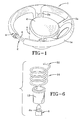
- each spring 14 has an extended portion 22 that protrudes outside the theoretical cylinder of the helical spring (see Figure 6).
- the extension 22 is V-shaped and is substantially contained in a plane perpendicular to the axis of the helical spring. Said extended portion 22 constitutes a second electrical contact intended to come into contact with the first electrical contact 21a to actuate the horn.
- the upper end of the spring 14 is covered with a cap 23 comprising a plastics component which has a central hole 23a to allow the screw 8 to pass through and is shaped so as to be able to cover the upper circular end of the helical spring with its extended portion 22.
- the flexible strip 16 is extended into a portion 16a ending in a plastics body 17 of a connector for connecting the electrical tracks 17, 18 to the motor vehicle's on-board electric power supply.
- FIGs 4 and 5 illustrate the mounting of each screw 8.
- a conical metallic washer 24 is fitted which, in the mounted state ( Figure 5), is interposed between the plastics cap 23 and a wall of the stirrup 7.
- the washer 24 is forced to adopt a flattened state with its internal annular edge bearing within a circumferential neck 25 of the body of the screw 8, so as to act as an anti-unscrewing device for the screw.
- each screw 8 is rigidly connected to the air bag module and thus acts as a support and guide element for said module.
- the airbag module is returned towards its resting position by the three helical springs 14.
- the module By exerting hand pressure on the cover 6, the module may be lowered as far as to bring the upper end 22 of at least one of the springs 14 into contact with the respective electrical contact 21a and so actuate the horn.
- the whole unit illustrated in Figures 2, 3 may be preassembled and mounted in the steering wheel in a single operation, after which the airbag module may be mounted by screwing in the screws 8 through the passage in the framework 11.
- the specific shape of the helical springs 14 which return the airbag module towards its resting position ensures, on the one hand, simplicity of manufacture and, on the other, an effective return action of the airbag module towards the resting position.
- the above-described shape of the springs means that the springs themselves may be used as electrical contact means for actuating the horn.
Landscapes
- Engineering & Computer Science (AREA)
- Mechanical Engineering (AREA)
- Physics & Mathematics (AREA)
- Acoustics & Sound (AREA)
- Air Bags (AREA)
- Steering Controls (AREA)
Abstract
Description
- The present invention relates to motor vehicle steering wheels comprising an airbag module and to horn actuating devices mounted on steering wheels of this type.
- In Italian patent application TO98A000795 of 17 September 1998, the applicant proposed a motor vehicle steering wheel of the above-stated type comprising: a metallic framework comprising a hub, a ring and a plurality of spokes joining the hub to the ring, an actuating element, typically constituted by an airbag module, which is mounted on the framework of the steering wheel in movable manner between a raised resting position and a lowered horn actuating position, resilient means interposed between said actuating element and said steering wheel framework to return the actuating element to its raised position, a horn actuating device interposed between the actuating element and the steering wheel framework and comprising at least a first electrical contact rigidly connected to the steering wheel framework and at least a second electrical contact which moves with the actuating element and is intended to cooperate with said first electrical contact for actuation of the horn, in which said resilient means are constituted by a plurality of springs, each of which exhibits a fixed base portion supported by the steering wheel framework and a portion operatively associated with the actuating element and having a free end suitable for constituting said second electrical contact which cooperates with said first electrical contact, and in which moreover said springs are mounted on respective plastics supports interconnected by a flexible plastics strip in which are embedded two conductive tracks, respectively connected electrically to each spring and to the first electrical contact cooperating therewith, in such a manner as to form a preassembled unit adapted to the steering wheel framework.
- With the aim of further improving the above-specified device from the standpoint of simplicity of manufacture and efficiency of operation, the present invention provides a steering wheel exhibiting all the above-stated features and furthermore characterised in that said springs are helical springs each having a free end constituting said second electrical contact constituted by an extended portion protruding outside the theoretical cylinder of the helical spring.
- In a preferred embodiment, said extended portion is a V-shaped portion contained in a plane perpendicular to the axis of the spring.
- Still in the case of said preferred embodiment, there is applied onto each spring an end cap made from plastics which also covers said extended portion which acts as the second electrical contact. Screws are attached to said actuating element, namely to the airbag module, each slidingly mounted from beneath through the steering wheel framework and through a respective helical spring and each having a head suitable for bearing against the lower surface of the steering wheel framework to define an extreme resting position of the airbag module, against which the module is returned by said helical springs.
- Still in the case of said preferred embodiment, each screw is restrained from unthreading by a metallic washer interposed between said end cap of each helical spring and a wall of the airbag module, which washer when in the mounted state bears with its internal annular edge within a circumferential neck of the body of the respective screw.
- Further features and advantages of the invention will be evident from the following description which refers to the attached drawings, which are provided purely by way of non-limiting examples and in which;
- Figure 1 is a perspective view of a preferred embodiment of the steering wheel according to the invention;
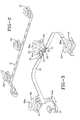
- Figure 2 is a perspective view of the preassembled unit constituting the horn actuating device according to the invention in its state prior to mounting on the steering wheel;
- Figure 3 is a perspective view of the unit of Figure 2 in the state it assumes on the motor vehicle steering wheel;
- Figures 4 and 5 are enlarged scale cross-sectional views which show the details of one of the constituent springs of the unit according to the invention before and after mounting on the motor vehicle steering wheel; and
- Figure 6 is a perspective exploded view of a detail of Figure 4.
-
- With reference to the drawings, the
number 1 denotes a motor vehicle steering wheel in its entirety comprising ametallic framework 2 covered in manner known per se with plastics padding 3. Theframework 2 comprises a circle 4 connected by means of metallic spokes 3 (a portion of one of which is visible in Figures 4, 5) to a hub (not shown in the drawings) intended to be fixed to the motor vehicle's steering column. Likewise, thepadding 3 comprises acircumferential portion 4a which covers the circle 4, threespoke portions 3a which cover thecorresponding spokes 3 of the metallic framework and acentral body 5 connected to thespokes 3a and surmounted by acover 6 which is associated with an airbag module. The structure and shape of said module is neither described nor illustrated here since it may be implemented in any known embodiment. What is important for the purposes of understanding the invention is that thecover 6 of the module has stirrups 7 (only one of which is shown in Figure 5) on its internal surface for fixing the support andguide screws 8. Eachstirrup 7 comprises a blind threadedhole 9, into which is screwed a threadedend portion 8a of therespective screw 8. Said screw is inserted from beneath through ahole 10 located in anintermediate portion 11 of the respectivemetallic spoke 3. Theintermediate portion 11 is substantially flat and perpendicular to the axis of the steering wheel. Thescrew 8 is slidingly mounted through thehole 10 of the metallic framework with an interposedplastics sleeve 12. At its lower end, thescrew 8 has ahead 13 that bears against the lower surface of the metallic framework in the extreme upper position of the airbag module. Said module, with thecover 6 which is a constituent part thereof, is returned towards said extreme upper position by a plurality of (in this case 3)helical springs 14. The lower end of eachhelical spring 14 rests on theframework 11 with an interposedplastic component 15 that defines a seat for the spring. As can be seen in Figures 2, 3, the plastics supports 15 are interconnected by aflexible plastics strip 16 in which are embedded twoconductive tracks support 15, twowings 19 leave thetrack 17 and extend to form ametallic contact 20 which is embedded in theplastics support 15 and is in electrical contact with the lower end of the respectivehelical spring 14. Still at eachsupport 15, awing 21 leaves thetrack 18 this time, theend 21a of which wing defines a first electrical contact of the motor vehicle's horn actuating device. - The upper end of each
spring 14 has an extendedportion 22 that protrudes outside the theoretical cylinder of the helical spring (see Figure 6). Theextension 22 is V-shaped and is substantially contained in a plane perpendicular to the axis of the helical spring. Said extendedportion 22 constitutes a second electrical contact intended to come into contact with the firstelectrical contact 21a to actuate the horn. - The upper end of the
spring 14 is covered with acap 23 comprising a plastics component which has acentral hole 23a to allow thescrew 8 to pass through and is shaped so as to be able to cover the upper circular end of the helical spring with its extendedportion 22. - With reference to Figures 2 and 3, the
flexible strip 16 is extended into aportion 16a ending in aplastics body 17 of a connector for connecting theelectrical tracks - Figures 4 and 5 illustrate the mounting of each
screw 8. As can be seen in Figure 4, before the airbag module is applied onto theupper end 8a of thescrew 8, a conicalmetallic washer 24 is fitted which, in the mounted state (Figure 5), is interposed between theplastics cap 23 and a wall of thestirrup 7. Once thescrew 8 has been screwed into thehole 9 of thestirrup 7, thewasher 24 is forced to adopt a flattened state with its internal annular edge bearing within acircumferential neck 25 of the body of thescrew 8, so as to act as an anti-unscrewing device for the screw. Once mounted in this manner, eachscrew 8 is rigidly connected to the air bag module and thus acts as a support and guide element for said module. The airbag module is returned towards its resting position by the threehelical springs 14. By exerting hand pressure on thecover 6, the module may be lowered as far as to bring theupper end 22 of at least one of thesprings 14 into contact with the respectiveelectrical contact 21a and so actuate the horn. The whole unit illustrated in Figures 2, 3 may be preassembled and mounted in the steering wheel in a single operation, after which the airbag module may be mounted by screwing in thescrews 8 through the passage in theframework 11. - The specific shape of the
helical springs 14 which return the airbag module towards its resting position ensures, on the one hand, simplicity of manufacture and, on the other, an effective return action of the airbag module towards the resting position. Finally, the above-described shape of the springs means that the springs themselves may be used as electrical contact means for actuating the horn. - Of course, while sticking to the principle of the invention, it is possible for constructive details and embodiments to differ widely from what has been described and illustrated above purely by way of example without as a result falling outside the scope of the present invention.
Claims (5)
- A motor vehicle steering wheel comprising:a metallic framework (2) comprising a hub, a ring (4) and a plurality of spokes (3) joining the hub to the ring (4),an actuating element (6, 7), typically constituted by an airbag module, which is mounted on the framework (2) of the steering wheel in movable manner between a raised resting position and a lowered horn actuating position,resilient means (14) interposed between said actuating element (6, 7) and said steering wheel framework (2) to return the actuating element to its raised position,a horn actuating device interposed between the actuating element (6, 7) and the steering wheel framework (2) and comprising at least a first electrical contact (21a) rigidly connected to the steering wheel framework (2) and at least a second electrical contact (22) which moves with the actuating element and is intended to cooperate with said first electrical contact (21a) for actuation of the horn,in which said resilient means are constituted by a plurality of springs (14), each of which exhibits a fixed base portion supported by the steering wheel framework (2) and a portion operatively associated with the actuating element (6, 7) and having a free end (22) suitable for constituting said second electrical contact which cooperates with said first electrical [contact] (21a), andin which moreover said springs (14) are mounted on respective plastics supports (15) interconnected by a flexible plastics strip (16) in which are embedded two conductive tracks (17, 18), respectively connected electrically to each spring (14) and to the first electrical contact (21a) cooperating therewith, in such a manner as to form a preassembled unit adapted to the steering wheel framework (2),
characterised in that said springs (14) are helical springs each having said free end acting as the second electrical contact constituted by an extended portion (22) protruding outside the theoretical cylinder of the helical spring (14). - A steering wheel according to claim 1, characterised in that said extended portion (22) is a V-shaped portion contained in a plane perpendicular to the axis of the spring.
- A steering wheel according to claim 2, characterised in that there is applied onto each spring an end cap (23) made from plastics which also covers said extended portion (22) which acts as an electrical contact.
- A steering wheel according to claim 2, characterised in that screws (8) are attached to said actuating element, each slidingly mounted from beneath through the steering wheel framework (2) and through a respective helical spring (14), each screw (8) having a head (13) suitable for bearing against the lower surface of the steering wheel framework (2) in the extreme resting position of the actuating element.
- A steering wheel according to claim 4, characterised in that, between said actuating element and the upper end of each helical spring (14), there is interposed a washer (24) suitable for bearing with its internal annular edge within a circumferential neck (25) of the body of the respective screw (8) in the mounted state of the screw on the actuating element.
Applications Claiming Priority (2)
| Application Number | Priority Date | Filing Date | Title |
|---|---|---|---|
| ITTO20010784 | 2001-08-03 | ||
| IT2001TO000784A ITTO20010784A1 (en) | 2001-08-03 | 2001-08-03 | HORSE WARNING DEVICE FOR A VEHICLE STEERING WHEEL. |
Publications (2)
| Publication Number | Publication Date |
|---|---|
| EP1281584A1 true EP1281584A1 (en) | 2003-02-05 |
| EP1281584B1 EP1281584B1 (en) | 2004-09-22 |
Family
ID=11459125
Family Applications (1)
| Application Number | Title | Priority Date | Filing Date |
|---|---|---|---|
| EP02014992A Expired - Lifetime EP1281584B1 (en) | 2001-08-03 | 2002-07-10 | Horn actuating device for a motor vehicle steering wheel |
Country Status (4)
| Country | Link |
|---|---|
| US (1) | US6722227B2 (en) |
| EP (1) | EP1281584B1 (en) |
| DE (1) | DE60201308T2 (en) |
| IT (1) | ITTO20010784A1 (en) |
Cited By (4)
| Publication number | Priority date | Publication date | Assignee | Title |
|---|---|---|---|---|
| US6860509B2 (en) * | 2002-02-08 | 2005-03-01 | Key Safety Systems, Inc. | Switch assembly for an airbag module attachment |
| EP1481848A3 (en) * | 2003-05-28 | 2005-04-06 | Methode Electronics Malta Ltd. | Switch for generating a warning signal in a vehicle |
| CN102490653A (en) * | 2011-12-20 | 2012-06-13 | 重庆长安汽车股份有限公司 | Electric horn conducting column assembly of vehicle |
| WO2018141540A1 (en) * | 2017-02-06 | 2018-08-09 | Trw Automotive Safety Systems Gmbh | Horn actuation unit |
Families Citing this family (18)
| Publication number | Priority date | Publication date | Assignee | Title |
|---|---|---|---|---|
| KR100477245B1 (en) * | 2002-07-05 | 2005-03-17 | 현대모비스 주식회사 | air bag module having horn switch |
| DE20210741U1 (en) * | 2002-07-16 | 2002-11-28 | TRW Automotive Safety Systems GmbH & Co. KG, 63743 Aschaffenburg | Vehicle steering wheel |
| JP2005038811A (en) * | 2003-06-30 | 2005-02-10 | Takata Corp | Horn switching device and air bag device |
| US7268309B2 (en) | 2003-06-30 | 2007-09-11 | Takata Corporation | Horn switch gear and airbag system |
| DE20315868U1 (en) * | 2003-10-15 | 2004-02-26 | Trw Automotive Safety Systems Gmbh | Steering wheel horn contact unit and assembly |
| ES2295852T3 (en) * | 2004-04-13 | 2008-04-16 | Dalphi Metal España, S.A. | CAR WHEEL WITH FIXED MODULE. |
| JP2006228699A (en) * | 2004-12-17 | 2006-08-31 | Takata Corp | Horn switch device, air bag device, and steering wheel |
| US7823908B2 (en) * | 2007-10-02 | 2010-11-02 | Autoliv Asp, Inc. | Airbag module assembly to control gap adjacent airbag cover |
| DE102008023004B4 (en) * | 2008-05-09 | 2014-04-03 | Autoliv Development Ab | Hupenaktivierungseinrichtung and safety device with such a Hupenaktivierungseinrichtung |
| DE102009043372B4 (en) * | 2009-09-29 | 2014-03-13 | Autoliv Development Ab | Horn activation device and safety arrangement with a horn activation device |
| US8205908B2 (en) | 2010-06-09 | 2012-06-26 | Autoliv Asp, Inc. | Inflatable airbag assembly having a cosmetic cover with a flexible mounting bracket |
| DE102011008158A1 (en) * | 2011-01-10 | 2012-07-12 | Autoliv Development Ab | Horn activation device |
| DE102016124530A1 (en) * | 2016-12-15 | 2018-06-21 | Trw Automotive Safety Systems Gmbh | Coupling device for vibratory mounting of a gas bag module to a vehicle steering wheel |
| US11718257B2 (en) * | 2016-12-15 | 2023-08-08 | Zf Passive Safety Systems Us Inc | Coupling device for mounting an airbag module to be oscillating on a vehicle steering wheel |
| JP6809427B2 (en) * | 2017-09-28 | 2021-01-06 | 豊田合成株式会社 | Steering wheel |
| DE102018112224A1 (en) * | 2018-05-22 | 2019-11-28 | Trw Automotive Safety Systems Gmbh | Vehicle steering wheel and steering wheel assembly with such a vehicle steering wheel |
| CN112440920B (en) * | 2019-08-27 | 2022-11-01 | 宁波均胜汽车安全系统有限公司 | Shock attenuation owner drives air bag |
| KR20240033489A (en) * | 2022-09-05 | 2024-03-12 | 현대자동차주식회사 | Steering wheel and damper unit of the steering wheel |
Citations (3)
| Publication number | Priority date | Publication date | Assignee | Title |
|---|---|---|---|---|
| US4434338A (en) * | 1982-01-22 | 1984-02-28 | Rood Robert M | Coil spring switch |
| EP0744329A1 (en) * | 1994-12-07 | 1996-11-27 | Kabushiki Kaisha Tokai-Rika-Denki-Seisakusho | Horn switch for steering wheels and pad mounting structure therefor |
| EP1099604A2 (en) * | 1999-09-24 | 2001-05-16 | Gallino Plasturgia S.r.L. | "Horn actuating device for a motor-vehicle steering wheel" |
Family Cites Families (5)
| Publication number | Priority date | Publication date | Assignee | Title |
|---|---|---|---|---|
| JP3123166B2 (en) * | 1991-12-17 | 2001-01-09 | タカタ株式会社 | Module cover for airbag device |
| DE69725246T2 (en) * | 1996-08-06 | 2004-07-29 | Toyoda Gosei Co., Ltd., Haruhi | steering wheel |
| DE29805210U1 (en) * | 1998-03-23 | 1998-06-04 | TRW Automotive Safety Systems GmbH, 63743 Aschaffenburg | Impact protection device |
| DE29805207U1 (en) * | 1998-03-23 | 1998-06-04 | TRW Automotive Safety Systems GmbH, 63743 Aschaffenburg | Steering wheel with an airbag |
| US6082758A (en) * | 1998-08-17 | 2000-07-04 | General Motors Corporation | Driver air bag horn ground spring |
-
2001
- 2001-08-03 IT IT2001TO000784A patent/ITTO20010784A1/en unknown
-
2002
- 2002-04-19 US US10/125,504 patent/US6722227B2/en not_active Expired - Fee Related
- 2002-07-10 EP EP02014992A patent/EP1281584B1/en not_active Expired - Lifetime
- 2002-07-10 DE DE60201308T patent/DE60201308T2/en not_active Expired - Lifetime
Patent Citations (3)
| Publication number | Priority date | Publication date | Assignee | Title |
|---|---|---|---|---|
| US4434338A (en) * | 1982-01-22 | 1984-02-28 | Rood Robert M | Coil spring switch |
| EP0744329A1 (en) * | 1994-12-07 | 1996-11-27 | Kabushiki Kaisha Tokai-Rika-Denki-Seisakusho | Horn switch for steering wheels and pad mounting structure therefor |
| EP1099604A2 (en) * | 1999-09-24 | 2001-05-16 | Gallino Plasturgia S.r.L. | "Horn actuating device for a motor-vehicle steering wheel" |
Cited By (4)
| Publication number | Priority date | Publication date | Assignee | Title |
|---|---|---|---|---|
| US6860509B2 (en) * | 2002-02-08 | 2005-03-01 | Key Safety Systems, Inc. | Switch assembly for an airbag module attachment |
| EP1481848A3 (en) * | 2003-05-28 | 2005-04-06 | Methode Electronics Malta Ltd. | Switch for generating a warning signal in a vehicle |
| CN102490653A (en) * | 2011-12-20 | 2012-06-13 | 重庆长安汽车股份有限公司 | Electric horn conducting column assembly of vehicle |
| WO2018141540A1 (en) * | 2017-02-06 | 2018-08-09 | Trw Automotive Safety Systems Gmbh | Horn actuation unit |
Also Published As
| Publication number | Publication date |
|---|---|
| US20030024342A1 (en) | 2003-02-06 |
| DE60201308T2 (en) | 2005-10-06 |
| ITTO20010784A0 (en) | 2001-08-03 |
| ITTO20010784A1 (en) | 2003-02-03 |
| DE60201308D1 (en) | 2004-10-28 |
| US6722227B2 (en) | 2004-04-20 |
| EP1281584B1 (en) | 2004-09-22 |
Similar Documents
| Publication | Publication Date | Title |
|---|---|---|
| EP1281584A1 (en) | Horn actuating device for a motor vehicle steering wheel | |
| US6457379B1 (en) | Horn actuating device for a motor-vehicle steering-wheel | |
| US6572138B1 (en) | Steering wheel with integrated gas bag | |
| US6086090A (en) | Vehicle steering wheel with integrated gas bag module | |
| EP1834843B1 (en) | Vehicle steering wheel with floating horn | |
| JP2005511407A (en) | Steering wheel mechanism | |
| US20040046367A1 (en) | Airbag module and assembly of steering wheel and airbag module | |
| US20020124682A1 (en) | Vehicle steering wheel | |
| JP2003525808A (en) | Automotive steering wheel having a switching device for activating an electrical functional group of the vehicle | |
| US5186423A (en) | Fallable type pole supporting device | |
| JP5465557B2 (en) | Vehicle lighting | |
| WO2008051117A1 (en) | A horn-actuator and a safety arrangement for a motor vehicle comprising a horn-actuator | |
| CN213892769U (en) | Balance car pedal, balance car pedal assembly and balance car | |
| JP2520590Y2 (en) | Bell device | |
| US7317118B2 (en) | Model car having adjustable parts | |
| CN206297472U (en) | Intelligent inside rear-view mirror mounting bracket | |
| CN219096886U (en) | Vehicle small bell with improve safety of traveling | |
| JPS6030135Y2 (en) | steering wheel | |
| CN213892768U (en) | Pedal for balance car, pedal assembly for balance car and balance car | |
| US6455792B1 (en) | Steering wheel with a moving contact | |
| CN112407123A (en) | Balance car with middle shell | |
| JPH0444455Y2 (en) | ||
| JPS6218139Y2 (en) | ||
| KR100337776B1 (en) | Horn mounting means of steering wheel | |
| CN101746435B (en) | Mounting structure for ignition switch lock cover of motor cycle |
Legal Events
| Date | Code | Title | Description |
|---|---|---|---|
| PUAI | Public reference made under article 153(3) epc to a published international application that has entered the european phase |
Free format text: ORIGINAL CODE: 0009012 |
|
| 17P | Request for examination filed |
Effective date: 20020930 |
|
| AK | Designated contracting states |
Designated state(s): AT BE BG CH CY CZ DE DK EE ES FI FR GB GR IE IT LI LU MC NL PT SE SK TR |
|
| AX | Request for extension of the european patent |
Extension state: AL LT LV MK RO SI |
|
| 17Q | First examination report despatched |
Effective date: 20030514 |
|
| AKX | Designation fees paid |
Designated state(s): DE FR GB IT |
|
| GRAP | Despatch of communication of intention to grant a patent |
Free format text: ORIGINAL CODE: EPIDOSNIGR1 |
|
| RAP1 | Party data changed (applicant data changed or rights of an application transferred) |
Owner name: KEY SAFETY SYSTEMS, INC. |
|
| GRAS | Grant fee paid |
Free format text: ORIGINAL CODE: EPIDOSNIGR3 |
|
| GRAA | (expected) grant |
Free format text: ORIGINAL CODE: 0009210 |
|
| AK | Designated contracting states |
Kind code of ref document: B1 Designated state(s): DE FR GB IT |
|
| REG | Reference to a national code |
Ref country code: GB Ref legal event code: FG4D |
|
| REG | Reference to a national code |
Ref country code: IE Ref legal event code: FG4D |
|
| REF | Corresponds to: |
Ref document number: 60201308 Country of ref document: DE Date of ref document: 20041028 Kind code of ref document: P |
|
| ET | Fr: translation filed | ||
| PLBE | No opposition filed within time limit |
Free format text: ORIGINAL CODE: 0009261 |
|
| STAA | Information on the status of an ep patent application or granted ep patent |
Free format text: STATUS: NO OPPOSITION FILED WITHIN TIME LIMIT |
|
| 26N | No opposition filed |
Effective date: 20050623 |
|
| PGFP | Annual fee paid to national office [announced via postgrant information from national office to epo] |
Ref country code: DE Payment date: 20100730 Year of fee payment: 9 Ref country code: FR Payment date: 20100813 Year of fee payment: 9 Ref country code: GB Payment date: 20100616 Year of fee payment: 9 Ref country code: IT Payment date: 20100722 Year of fee payment: 9 |
|
| GBPC | Gb: european patent ceased through non-payment of renewal fee |
Effective date: 20110710 |
|
| REG | Reference to a national code |
Ref country code: FR Ref legal event code: ST Effective date: 20120330 |
|
| PG25 | Lapsed in a contracting state [announced via postgrant information from national office to epo] |
Ref country code: FR Free format text: LAPSE BECAUSE OF NON-PAYMENT OF DUE FEES Effective date: 20110801 Ref country code: DE Free format text: LAPSE BECAUSE OF NON-PAYMENT OF DUE FEES Effective date: 20120201 |
|
| REG | Reference to a national code |
Ref country code: DE Ref legal event code: R119 Ref document number: 60201308 Country of ref document: DE Effective date: 20120201 |
|
| PG25 | Lapsed in a contracting state [announced via postgrant information from national office to epo] |
Ref country code: IT Free format text: LAPSE BECAUSE OF NON-PAYMENT OF DUE FEES Effective date: 20110710 |
|
| PG25 | Lapsed in a contracting state [announced via postgrant information from national office to epo] |
Ref country code: GB Free format text: LAPSE BECAUSE OF NON-PAYMENT OF DUE FEES Effective date: 20110710 |