EP1282888B1 - Dispositif de balisage pour aeronefs monte sur des eoliennes - Google Patents
Dispositif de balisage pour aeronefs monte sur des eoliennes Download PDFInfo
- Publication number
- EP1282888B1 EP1282888B1 EP01951485A EP01951485A EP1282888B1 EP 1282888 B1 EP1282888 B1 EP 1282888B1 EP 01951485 A EP01951485 A EP 01951485A EP 01951485 A EP01951485 A EP 01951485A EP 1282888 B1 EP1282888 B1 EP 1282888B1
- Authority
- EP
- European Patent Office
- Prior art keywords
- wind farm
- lighting means
- farm according
- flight navigation
- wind
- Prior art date
- Legal status (The legal status is an assumption and is not a legal conclusion. Google has not performed a legal analysis and makes no representation as to the accuracy of the status listed.)
- Revoked
Links
Images


Classifications
-
- F—MECHANICAL ENGINEERING; LIGHTING; HEATING; WEAPONS; BLASTING
- F21—LIGHTING
- F21S—NON-PORTABLE LIGHTING DEVICES; SYSTEMS THEREOF; VEHICLE LIGHTING DEVICES SPECIALLY ADAPTED FOR VEHICLE EXTERIORS
- F21S9/00—Lighting devices with a built-in power supply; Systems employing lighting devices with a built-in power supply
- F21S9/04—Lighting devices with a built-in power supply; Systems employing lighting devices with a built-in power supply the power supply being a generator
- F21S9/043—Lighting devices with a built-in power supply; Systems employing lighting devices with a built-in power supply the power supply being a generator driven by wind power, e.g. by wind turbines
-
- G—PHYSICS
- G08—SIGNALLING
- G08G—TRAFFIC CONTROL SYSTEMS
- G08G5/00—Traffic control systems for aircraft
- G08G5/80—Anti-collision systems
-
- F—MECHANICAL ENGINEERING; LIGHTING; HEATING; WEAPONS; BLASTING
- F03—MACHINES OR ENGINES FOR LIQUIDS; WIND, SPRING, OR WEIGHT MOTORS; PRODUCING MECHANICAL POWER OR A REACTIVE PROPULSIVE THRUST, NOT OTHERWISE PROVIDED FOR
- F03D—WIND MOTORS
- F03D80/00—Details, components or accessories not provided for in groups F03D1/00 - F03D17/00
- F03D80/10—Arrangements for warning air traffic
-
- F—MECHANICAL ENGINEERING; LIGHTING; HEATING; WEAPONS; BLASTING
- F21—LIGHTING
- F21V—FUNCTIONAL FEATURES OR DETAILS OF LIGHTING DEVICES OR SYSTEMS THEREOF; STRUCTURAL COMBINATIONS OF LIGHTING DEVICES WITH OTHER ARTICLES, NOT OTHERWISE PROVIDED FOR
- F21V23/00—Arrangement of electric circuit elements in or on lighting devices
- F21V23/04—Arrangement of electric circuit elements in or on lighting devices the elements being switches
-
- G—PHYSICS
- G08—SIGNALLING
- G08B—SIGNALLING SYSTEMS, e.g. PERSONAL CALLING SYSTEMS; ORDER TELEGRAPHS; ALARM SYSTEMS
- G08B5/00—Visible signalling systems, e.g. visible personal calling systems or remote indication of seats occupied
-
- F—MECHANICAL ENGINEERING; LIGHTING; HEATING; WEAPONS; BLASTING
- F21—LIGHTING
- F21S—NON-PORTABLE LIGHTING DEVICES; SYSTEMS THEREOF; VEHICLE LIGHTING DEVICES SPECIALLY ADAPTED FOR VEHICLE EXTERIORS
- F21S9/00—Lighting devices with a built-in power supply; Systems employing lighting devices with a built-in power supply
- F21S9/02—Lighting devices with a built-in power supply; Systems employing lighting devices with a built-in power supply the power supply being a battery or accumulator
- F21S9/022—Emergency lighting devices
-
- F—MECHANICAL ENGINEERING; LIGHTING; HEATING; WEAPONS; BLASTING
- F21—LIGHTING
- F21W—INDEXING SCHEME ASSOCIATED WITH SUBCLASSES F21K, F21L, F21S and F21V, RELATING TO USES OR APPLICATIONS OF LIGHTING DEVICES OR SYSTEMS
- F21W2111/00—Use or application of lighting devices or systems for signalling, marking or indicating, not provided for in codes F21W2102/00 – F21W2107/00
- F21W2111/06—Use or application of lighting devices or systems for signalling, marking or indicating, not provided for in codes F21W2102/00 – F21W2107/00 for aircraft runways or the like
-
- F—MECHANICAL ENGINEERING; LIGHTING; HEATING; WEAPONS; BLASTING
- F21—LIGHTING
- F21Y—INDEXING SCHEME ASSOCIATED WITH SUBCLASSES F21K, F21L, F21S and F21V, RELATING TO THE FORM OR THE KIND OF THE LIGHT SOURCES OR OF THE COLOUR OF THE LIGHT EMITTED
- F21Y2115/00—Light-generating elements of semiconductor light sources
- F21Y2115/10—Light-emitting diodes [LED]
-
- Y—GENERAL TAGGING OF NEW TECHNOLOGICAL DEVELOPMENTS; GENERAL TAGGING OF CROSS-SECTIONAL TECHNOLOGIES SPANNING OVER SEVERAL SECTIONS OF THE IPC; TECHNICAL SUBJECTS COVERED BY FORMER USPC CROSS-REFERENCE ART COLLECTIONS [XRACs] AND DIGESTS
- Y02—TECHNOLOGIES OR APPLICATIONS FOR MITIGATION OR ADAPTATION AGAINST CLIMATE CHANGE
- Y02B—CLIMATE CHANGE MITIGATION TECHNOLOGIES RELATED TO BUILDINGS, e.g. HOUSING, HOUSE APPLIANCES OR RELATED END-USER APPLICATIONS
- Y02B10/00—Integration of renewable energy sources in buildings
- Y02B10/30—Wind power
-
- Y—GENERAL TAGGING OF NEW TECHNOLOGICAL DEVELOPMENTS; GENERAL TAGGING OF CROSS-SECTIONAL TECHNOLOGIES SPANNING OVER SEVERAL SECTIONS OF THE IPC; TECHNICAL SUBJECTS COVERED BY FORMER USPC CROSS-REFERENCE ART COLLECTIONS [XRACs] AND DIGESTS
- Y02—TECHNOLOGIES OR APPLICATIONS FOR MITIGATION OR ADAPTATION AGAINST CLIMATE CHANGE
- Y02E—REDUCTION OF GREENHOUSE GAS [GHG] EMISSIONS, RELATED TO ENERGY GENERATION, TRANSMISSION OR DISTRIBUTION
- Y02E10/00—Energy generation through renewable energy sources
- Y02E10/70—Wind energy
- Y02E10/72—Wind turbines with rotation axis in wind direction
Definitions
- the present invention relates to a wind farm according to claim 1.
- the night marking is at an overall height (rotor blade in 12.00 o'clock position) under 100 m from a so-called obstruction fire, while with a total height over 100 m a so-called danger fire is necessary.
- An obstacle lighting usually consists of two bulbs (two lights), which are permanently lit at night, while the danger fire has two flashing lights (and two reserve lights), in the given rhythm alternately light up.
- the intensity of a danger fire is many times stronger than the intensity of an obstacle fire.
- an emergency power supply must also be provided.
- WO 97/29320 shows a flight firing device for warning pilots of obstacles.
- a photocell is provided here to turn on the bulbs when it gets dark.
- US 4,620,190 shows a device for operating navigation lanterns, which are switched on and activated simultaneously at dusk.
- JP 11182409 shows a wind turbine with a flight beacon, wherein light bulbs are mounted in the rotor blades, which light up when the rotor blade rotates in a Vogelwam College, the bulb is switched off again when the rotor blade turns out of the aircraft warning area.
- the object of the invention is to improve a Flugbefeuerungs worn of wind turbines and in particular to make their operation as effective as possible.
- Such a brightness value can be determined by a twilight switch, which is set to a predetermined brightness value and the flight lighting is activated when a certain brightness value is reached (undershot).
- the wind turbine is equipped with a visibility meter.
- the visibility can be detected, which makes sense especially in fog or other unfavorable weather conditions (heavy rain). If, by means of the visibility meter, it falls below a certain visibility (the critical visibility can be set), the flight lights are also activated so that there is always adequate building safety.
- the invention provides for the formation of a synchronization device, by means of which the flashing lights are synchronized in such a way that all flashing lights of all wind turbines of a wind farm flash at the same time (that is, they are switched on or off).
- the synchronization can take place here via radio and / or data signals and the synchronization device can consist of a data processing device which generates the turn-on or turn-off signals of the flashing lights coupled with a movement, so that the purpose is achieved.
- a flight lighting device must be designed so safely in a wind turbine that it still has their functionality even if the entire wind turbine is removed from the electrical network or the rotor of the wind turbine is stationary. Therefore, an emergency power supply device for a wind turbine and its flight lighting is proposed, so that at least one night the flight lights can be maintained.
- a (preferably air-conditioned) control cabinet is provided in the wind turbine, in which the entire control devices for the flight lights are arranged and also also batteries or accumulators that provide the necessary energy for the flight lights. These batteries or accumulators are preferably absolutely maintenance-free.
- a central control cabinet for emergency power and control of the flight lights can also be provided.
- the flight lighting device controls not only the respective flight lights (obstacle lights, danger fires), but also monitors the disturbance various devices such as the failure of the supply voltage, the failure of a lamp, fault of the twilight switch, failure of batteries or the charger to recharge the batteries, fault the air conditioning of the cabinet, the failure of the visibility measurement (if it exists) and the failure of the synchronization (only with danger lighting).
- fault message If such a fault message is detected, it is automatically forwarded to a control center via the connection to the plant control.
- the transmission of the fault message to the control center can be done by fax, SMS or e-mail.
- the hazard lighting consists of two main lights and two reserve lights.
- the light intensity of the flashes is more than 1600 cd / flash.
- the flashes are housed in a housing of protection class IP 67.
- the light source here is a xenon flash tube with a nominal service life of approx. 2,000,000 flashes (corresponds to approx. 12 months).
- a main flashlight fails, it automatically switches over to the redundant second system (reserve light) and issues a fault message to the control panel.
- the obstacle lighting consists of two obstacle lights and is preferably designed with light sources made of LEDs.
- the bulbs are housed in a housing of protection class IP 67. Since the operating time of the above-described obstacle lights is detected, no redundant system is necessary in this structure. The use of LED bulbs, the power consumption is very low and the life of at least 10 years very high.
- Another aspect of the invention is concerned with the fact that in particular at construction sites, eg. B. for wind turbines on which the tower of the wind turbine is already built, the engine house, the rotor, the generator and the electrical installations, however, are not yet available, a Flugbefeuerungs adopted is missing, although the tower is quite an obstacle or a danger point.
- a flight lighting device is proposed in a Ausgestallung of the invention, which has a transportable power supply.
- a self-sufficient energy supply independent of a fixed installation, allows every building to be equipped with a flight lighting device if required. This allows the required in the interest of aviation safety marking this structure even if a power supply of this building (yet) is not made.
- a wind farm according to the invention may have the following features, which may be formed alone or in combinations.
- a device which in case of failure a fault message z. B. settles to a given center.
- a device preferably comprises a GSM module, the z. B. via a radio link a short message (SMS) can settle, which indicates the receiver to the fault.
- SMS short message
- a transport container may be provided, in which the individual components of the FlugbefeuerungsUNE, such as accumulators, switching device, GSM module, charge Regenerant, battery guard, etc. are housed.
- the luminaires may preferably be mounted on the cover of this transport device, so that the entire inventive flight firing device can be handled as a unit.
- the photovoltaic module and / or the generator provided so that they are also housed in the transport container for transport and therefore can not be lost.
- the generator and / or the photovoltaic module may be fastened to the transport container during operation or attached to it at low points at the top of the tower. This attachment can again take place via suitable holders (flanges).
- the lid of the container is advantageously designed such that it closes both with the attached lights pointing upwards, as well as with the attached lights down the container tightly closes and thus reliably protects its interior from the weather.
- the electrical connection between the switching device and the switching device is preferably made by a detachable cable connection.
- the cable connection is preferably on the switching device with one or more connectors solvable.
- the upper cover of the transport container, on which the lights are provided, has a compartment which receives the connection cable between the lights and the switching device.
- This compartment may have a cover which closes the compartment in the transport position of the container lid with luminaires projecting into the container.
- a radio receiver that receives signals from a central station such as the DCF transmitter of the Physikalisch-Technische Bundesweg and at predetermined times that can be derived from the radio signal, certain switching operations such as flashes for the lights triggers.
- a DCF receiver it is of course also possible to use a plurality of spatially adjacent flight beaconing devices via radio signals from a predefinable transmitting station, such as a radio station.
- a master system can be controlled.
- FIG. 1 shows a sketch of the frontal or side view of a wind energy plant with an obstacle or danger fire according to the invention. This obstacle and / or danger fire is located on the nacelle.
- FIG. 2 shows a transport container 20 with a switching device 22, in which a light monitoring can be integrated.
- This switching device 22 controls lights 10 in a predetermined manner, the z. B. by a fixed wiring or by a microprocessor control can be specified.
- the switching device can be influenced by external signals. These can come from a twilight switch 24.
- Such a twilight switch 24 is provided in order to influence the flight lighting device according to the invention, depending on the ambient brightness. This influence can be the switching on and off of the flight-lighting device at a certain ambient brightness.
- an energy storage 26 which may be formed of batteries and / or capacitors or the like.
- This energy store 26 can be fed by a generator for converting wind energy into electrical energy 28 and / or a photovoltaic module 29, which are connected to the energy store 26 via a charge controller 30.
- This charge controller 30 causes a charge of the accumulators or capacitors with suitable voltages and currents.
- the generator 28 and the photovoltaic module 29 have dimensions such that they can be accommodated in the transport container 20 for the transport of the flight firing device. As a result, they are protected against damage during transport and can not be lost, so that all components of the flight-lighting device are always present.
- two pairs of lights 10 are mounted on the transport container 20, one of which is the main pair of lights and the other is the reserve pair of lights. Furthermore, there is an antenna 34 on the transport container 20, which is connected to a GSM module 32 arranged in the container. About this GSM module 32 z. B. in the case of faults corresponding fault messages to predetermined recipients are sold.
- mounting flanges 40 are provided on the transport container 20, by means of which it can be fastened to the tower with screws.
- the electrical connection between the switching device 22 and the lights 10 is made by cable 12.
- These cables 12 are preferably detachable on the switching device 22, so that the cover of the transport container 20 with the lamps 10 attached thereto including the electrical connections can be completely detached from the transport container 20.
- the cover with the lights 10 attached thereto can then be placed on the transport container 20 such that the lights 10 are located in the interior of the transport container 20.
- the lid In this installation situation of the lid are now the cable 12 on the outside of the transport container 20.
- they can be stowed in a compartment 8, which is closable with a cover 9.
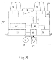
- FIG. 3 essentially corresponds to FIG. 2. The difference is that a switching device 23 is provided here.
- This switching device 23 receives the signals for controlling the lights 10 of the switching device 22 and forwards them to the lights 10. Furthermore, the switching device 23 is influenced by the twilight switch 24. In this case, the switching device is controlled so that, depending on the ambient brightness of one of the two pairs of lights 10 is applied to the signals of the switching device 22.
- the twilight switch 24 can be used alternatively to make the switch between daytime and nighttime lighting depending on the ambient brightness.
- the switching device required for switching between daytime lighting and nighttime lighting may be integrated into the switching device 22.
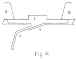
- FIG. 4 shows a detailed representation of a possible cable guide.
- the cables 12 are attached to the lights 10.
- the flap 9 pointing into the transport container is open and the cables 12 can be connected to the switching device 22 or the switching device 23.
- the cover is turned so that the lights 10 point downwards (into the transport container).
- the now located on top of the cable 12 are then unprotected, unless they are included in the compartment 8.
- they can be routed within a double-shell lid, and emerge from the lid in the region of the cover for the compartment 9 and guided to the switching device 22 or the switching device 23.
- the cables 12 can be stowed in the compartment 8.
- the cover 9, which is located during transport on the outside of the transport container, the compartment 8 and the interior of the double-shell lid protect from contamination and damage.
Landscapes
- Engineering & Computer Science (AREA)
- General Engineering & Computer Science (AREA)
- Life Sciences & Earth Sciences (AREA)
- Sustainable Development (AREA)
- Sustainable Energy (AREA)
- Physics & Mathematics (AREA)
- General Physics & Mathematics (AREA)
- Chemical & Material Sciences (AREA)
- Combustion & Propulsion (AREA)
- Mechanical Engineering (AREA)
- Aviation & Aerospace Engineering (AREA)
- Wind Motors (AREA)
- Road Signs Or Road Markings (AREA)
- Non-Portable Lighting Devices Or Systems Thereof (AREA)
- Audible And Visible Signals (AREA)
- Circuit Arrangement For Electric Light Sources In General (AREA)
- Lighting Device Outwards From Vehicle And Optical Signal (AREA)
- Navigation (AREA)
- Traffic Control Systems (AREA)
- Illuminated Signs And Luminous Advertising (AREA)
- Emergency Alarm Devices (AREA)
- Optical Communication System (AREA)
- Control Of Eletrric Generators (AREA)
- Refuge Islands, Traffic Blockers, Or Guard Fence (AREA)
- Thermistors And Varistors (AREA)
- Vehicle Body Suspensions (AREA)
- Cultivation Of Plants (AREA)
- Air-Conditioning For Vehicles (AREA)
- Circuit Arrangements For Discharge Lamps (AREA)
Claims (15)
- Parc d'éoliennes composé de plusieurs éoliennes, dans lequel différentes éoliennes du parc d'éoliennes sont équipées d'un dispositif de balisage pour aéronefs, dans lequel le dispositif de balisage pour aéronefs comporte :deux moyens d'éclairage (10) de couleurs différentes,un dispositif pour détecter une valeur de luminosité dans l'entourage du dispositif de balisage pour aéronefs,un dispositif interrupteur, lequel est relié au dispositif de détection de luminosité, dans lequel le dispositif interrupteur évalue les données mesurées du dispositif pour détecter la valeur de luminosité,un dispositif de synchronisation, au moyen duquel les moyens d'éclairage sont synchronisés de manière à ce que les moyens d'éclairage des éoliennes d'un parc d'éoliennes s'allument ou s'éteignent en même temps, etdans lequel le dispositif interrupteur agit conjointement avec un dispositif de commutation pour commuter d'un moyen d'éclairage d'une couleur vers un moyen d'éclairage d'une autre couleur, lorsqu'une certaine valeur de luminosité est atteinte.
- Parc d'éoliennes selon la revendication 1, dans lequel un dispositif pour mesurer la visibilité est prévu, au moyen duquel les moyens d'éclairage sont activés, lorsque l'on passe en dessous d'un certain seuil de visibilité.
- Parc d'éoliennes selon la revendication 1 ou 2, dans lequel le dispositif de synchronisation commande par une commande à signal radio et/ou à signal de données d'autres dispositifs de balisage pour aéronefs dans l'entourage du dispositif de balisage pour aéronefs.
- Parc d'éoliennes selon l'une quelconque des revendications 1 à 3, dans lequel le dispositif de balisage pour aéronefs comporte un récepteur radio pour recevoir des signaux d'un émetteur central, dans lequel le dispositif de synchronisation déduit à l'aide des signaux reçus par le récepteur radio des moments prescrits auxquels les moyens d'éclairage sont allumés.
- Parc d'éoliennes selon l'une quelconque des revendications précédentes, caractérisé en ce que le dispositif de balisage pour aéronefs comporte un moyen d'éclairage qui se compose d'une pluralité de DEL (diodes électroluminescentes).
- Parc d'éoliennes selon l'une quelconque des revendications précédentes, dans lequel le dispositif de balisage pour aéronefs comporte une source transportable d'énergie pour l'alimentation en énergie du moyen d'éclairage et du dispositif interrupteur.
- Parc d'éoliennes selon la revendication 6, dans lequel le dispositif de balisage pour aéronefs comporte un stockage intermédiaire d'énergie (26), qui peut être couplé avec un dispositif de production d'énergie (28, 29).
- Parc d'éoliennes selon la revendication 6, dans lequel le dispositif de balisage pour aéronefs comporte un module GSM (32) pour la transmission de signaux de dérangements.
- Parc d'éoliennes selon la revendication 6, caractérisé en ce que le moyen d'éclairage (10) peut être fixé à un conteneur de transport (20).
- Parc d'éoliennes selon la revendication 9, caractérisé en ce que la hauteur du conteneur de transport (20) est dimensionnée de façon à ce qu'au moins la hauteur du moyen d'éclairage (10) reste libre entre les objets installés dans le conteneur de transport (20) et le bord du conteneur de transport (20).
- Parc d'éoliennes selon la revendication 6, caractérisé en ce que le moyen d'éclairage (10) peut être disposé, au moins pendant le fonctionnement du dispositif de balisage pour aéronefs, séparément du conteneur de transport (20).
- Parc d'éoliennes selon la revendication 6, caractérisé par au moins une connexion électrique amovible au moins d'un côté, entre le moyen d'éclairage (10) et le dispositif interrupteur (22) ou le dispositif de commutation.
- Parc d'éoliennes selon la revendication 6, caractérisé par un compartiment de logement (8) pour des câbles.
- Parc d'éoliennes selon l'une quelconque des revendications précédentes, caractérisé en ce que le dispositif interrupteur (22) et/ou l'interrupteur crépusculaire (24) sont compris avec le moyen d'éclairage (10).
- Parc d'éoliennes selon la revendication 14, caractérisé par un dispositif de réception pour des signaux radio, lesquels agissent conjointement avec l'interrupteur crépusculaire (24) et/ou le dispositif interrupteur (22).
Priority Applications (4)
| Application Number | Priority Date | Filing Date | Title |
|---|---|---|---|
| EP12175268A EP2520853A1 (fr) | 2000-05-09 | 2001-05-08 | Dispositif de balisage pour aeronefs monte sur des eoliennes |
| EP08165143A EP2071535B1 (fr) | 2000-05-09 | 2001-05-08 | Balisage lumineux portatif pour aéronefs |
| EP05109416A EP1615185B1 (fr) | 2000-05-09 | 2001-05-08 | Dispositif de balisage pour aéronef monté sur des eoliennes |
| DK05109416.7T DK1615185T3 (da) | 2000-05-09 | 2001-05-08 | Flynavigationsindretning på vindenergianlæg |
Applications Claiming Priority (3)
| Application Number | Priority Date | Filing Date | Title |
|---|---|---|---|
| DE20008289U DE20008289U1 (de) | 2000-05-09 | 2000-05-09 | Flugbefeuerungseinrichtung an Windenergieanlagen |
| DE20008289U | 2000-05-09 | ||
| PCT/EP2001/005194 WO2001086606A1 (fr) | 2000-05-09 | 2001-05-08 | Dispositif de balisage pour aeronefs monte sur des eoliennes |
Related Child Applications (1)
| Application Number | Title | Priority Date | Filing Date |
|---|---|---|---|
| EP05109416A Division EP1615185B1 (fr) | 2000-05-09 | 2001-05-08 | Dispositif de balisage pour aéronef monté sur des eoliennes |
Publications (2)
| Publication Number | Publication Date |
|---|---|
| EP1282888A1 EP1282888A1 (fr) | 2003-02-12 |
| EP1282888B1 true EP1282888B1 (fr) | 2006-02-15 |
Family
ID=7941225
Family Applications (4)
| Application Number | Title | Priority Date | Filing Date |
|---|---|---|---|
| EP08165143A Expired - Lifetime EP2071535B1 (fr) | 2000-05-09 | 2001-05-08 | Balisage lumineux portatif pour aéronefs |
| EP05109416A Revoked EP1615185B1 (fr) | 2000-05-09 | 2001-05-08 | Dispositif de balisage pour aéronef monté sur des eoliennes |
| EP12175268A Ceased EP2520853A1 (fr) | 2000-05-09 | 2001-05-08 | Dispositif de balisage pour aeronefs monte sur des eoliennes |
| EP01951485A Revoked EP1282888B1 (fr) | 2000-05-09 | 2001-05-08 | Dispositif de balisage pour aeronefs monte sur des eoliennes |
Family Applications Before (3)
| Application Number | Title | Priority Date | Filing Date |
|---|---|---|---|
| EP08165143A Expired - Lifetime EP2071535B1 (fr) | 2000-05-09 | 2001-05-08 | Balisage lumineux portatif pour aéronefs |
| EP05109416A Revoked EP1615185B1 (fr) | 2000-05-09 | 2001-05-08 | Dispositif de balisage pour aéronef monté sur des eoliennes |
| EP12175268A Ceased EP2520853A1 (fr) | 2000-05-09 | 2001-05-08 | Dispositif de balisage pour aeronefs monte sur des eoliennes |
Country Status (18)
| Country | Link |
|---|---|
| US (2) | US6867710B2 (fr) |
| EP (4) | EP2071535B1 (fr) |
| JP (2) | JP3946522B2 (fr) |
| KR (1) | KR100582288B1 (fr) |
| AT (2) | ATE317998T1 (fr) |
| AU (3) | AU7239901A (fr) |
| BR (1) | BRPI0110720B1 (fr) |
| CA (1) | CA2408359C (fr) |
| CY (3) | CY1105021T1 (fr) |
| DE (3) | DE20008289U1 (fr) |
| DK (3) | DK1615185T3 (fr) |
| ES (3) | ES2255564T3 (fr) |
| NO (1) | NO20025337L (fr) |
| NZ (2) | NZ522526A (fr) |
| PL (2) | PL204360B1 (fr) |
| PT (2) | PT2071535E (fr) |
| WO (1) | WO2001086606A1 (fr) |
| ZA (1) | ZA200209219B (fr) |
Cited By (2)
| Publication number | Priority date | Publication date | Assignee | Title |
|---|---|---|---|---|
| EP2199608A1 (fr) | 2008-12-19 | 2010-06-23 | Siemens Aktiengesellschaft | Eolienne et procédé de fonctionnement d'un balisage d'obstacle ou de danger d'une éolienne |
| WO2012025205A1 (fr) | 2010-08-27 | 2012-03-01 | Repower Systems Se | Balise de danger ir |
Families Citing this family (39)
| Publication number | Priority date | Publication date | Assignee | Title |
|---|---|---|---|---|
| EP1280696A1 (fr) * | 2000-04-20 | 2003-02-05 | Navchannel Pty Ltd | Synchronisation a distance |
| DE20008289U1 (de) * | 2000-05-09 | 2000-08-10 | Wobben, Aloys, 26607 Aurich | Flugbefeuerungseinrichtung an Windenergieanlagen |
| DE10051513A1 (de) | 2000-10-17 | 2002-04-25 | Aloys Wobben | Windpark |
| DE10103387A1 (de) * | 2001-01-26 | 2002-08-01 | Thorsten Nordhoff | Windkraftanlage mit einer Einrichtung zur Hindernisbefeuerung bzw. Nachtkennzeichnung |
| DE20103294U1 (de) | 2001-02-14 | 2001-09-27 | Ballaschk, Bernd, 03096 Burg | Integrierte Rotor-Hindernisbefeuerungsanlage für Windenergieanlagen |
| EP2161447A3 (fr) | 2001-12-08 | 2014-12-03 | Aloys Wobben | Pale de rotor pour installation d'énergie éolienne avec lumière d'avertissement |
| DE10160360B4 (de) * | 2001-12-08 | 2004-04-22 | Wobben, Aloys, Dipl.-Ing. | Rotorblatt sowie eine Windenergieanlage mit einem Rotorblatt |
| DE10225288A1 (de) | 2002-06-07 | 2004-01-08 | Wobben, Aloys, Dipl.-Ing. | Windenergieanlage |
| WO2003104648A1 (fr) * | 2002-06-11 | 2003-12-18 | Uckerwerk Energietechnik Gmbh | Eolienne |
| US7557734B2 (en) * | 2004-04-05 | 2009-07-07 | The United States Of America As Represented By The Secretary Of The Army | Airborne visibility indicator system and method |
| BRPI0606591B1 (pt) | 2005-01-19 | 2017-04-25 | Wobben Aloys | lâmpada em forma de barra para sinalização luminosa de uma torre, instalação de energia eólica, elemento de torre, e, processo para montagem de uma sinalização luminosa de uma torre |
| US7758210B2 (en) * | 2005-03-03 | 2010-07-20 | Dialight Corporation | Beacon light with light-transmitting element and light-emitting diodes |
| US7568821B2 (en) * | 2005-03-03 | 2009-08-04 | Dialight Corporation | Beacon light with reflector and light-emitting diodes |
| US8591073B2 (en) | 2005-03-03 | 2013-11-26 | Dialight Corporation | Beacon light with reflector and light emitting diodes |
| DE102006007536A1 (de) * | 2006-02-16 | 2007-08-30 | Aloys Wobben | Windenergieanlage mit Flugbefeuerungseinrichtung |
| US8665138B2 (en) * | 2007-07-17 | 2014-03-04 | Laufer Wind Group Llc | Method and system for reducing light pollution |
| WO2009012231A1 (fr) * | 2007-07-17 | 2009-01-22 | Laufer Wind Group Llc | Procédé et système pour réduire la pollution lumineuse |
| JP4858400B2 (ja) | 2007-10-17 | 2012-01-18 | ソニー株式会社 | 情報提供システム、情報提供装置、情報提供方法 |
| FR2923062B1 (fr) * | 2007-10-30 | 2010-08-27 | Serco | Systeme de commande synchronisee de composants electriques d'une pluralite d'equipements |
| ES2353320B1 (es) * | 2008-02-08 | 2012-01-25 | Gamesa Innovation & Technology S.L. | Pala de aerogenerador con una baliza luminosa en su punta. |
| AU2009214813B2 (en) * | 2008-02-15 | 2014-04-10 | Ian Lloyd Whalan | Apparatus and methods for deterring predators |
| DE102008024380A1 (de) * | 2008-05-20 | 2009-11-26 | Repower Systems Ag | Signaleinrichtung für Offshore-Windpark |
| WO2009155921A1 (fr) * | 2008-06-23 | 2009-12-30 | Danmarks Tekniske Universitet | Pale d'éolienne avec poutrelle oblique |
| DE102008034747B3 (de) * | 2008-07-24 | 2009-09-10 | Wobben, Aloys | Gondel einer Windenergieanlage mit Flughindernisbefeuerungseinrichtung |
| DE102008054050A1 (de) * | 2008-10-30 | 2010-05-06 | Osram Opto Semiconductors Gmbh | Laterne und Verfahren zur Umrüstung einer Laterne |
| DE102009013311A1 (de) * | 2009-03-18 | 2010-09-30 | Suzlon Energy Gmbh | Antriebsvorrichtung für eine Windturbine |
| JP5207140B2 (ja) * | 2009-04-08 | 2013-06-12 | 東京電力株式会社 | 鳥類退避装置および風力発電装置 |
| FR2944619B1 (fr) | 2009-04-20 | 2011-04-08 | Georges Antonin Lapresle | Systeme de commande synchronisee de composants electriques d'une pluralite d'equipements |
| DK2325484T3 (da) * | 2009-11-24 | 2012-09-24 | Siemens Ag | Arrangement af en vindmøllenacelle med et instrument |
| US8851707B2 (en) | 2010-06-15 | 2014-10-07 | Dialight Corporation | Highly collimating reflector lens optic and light emitting diodes |
| US8963691B1 (en) | 2010-07-27 | 2015-02-24 | The Boeing Company | Sensor association system using wireless device information |
| ES2382424B1 (es) * | 2010-08-31 | 2013-04-01 | Nicolas Suarez Lencina | Dispositivo convertidor/alimentador de elementos de iluminacion con acumuladores |
| DE102010046394A1 (de) * | 2010-09-24 | 2012-03-29 | Repower Systems Ag | Offshore-Windpark Beleuchtung |
| CN102330944A (zh) * | 2011-09-28 | 2012-01-25 | 苏州晶雷光电照明科技有限公司 | 一种多功能路杆灯 |
| KR20160016752A (ko) * | 2013-03-21 | 2016-02-15 | 오스모 에스아 | 광섬유를 적용한 모니터링 장치를 통하여 회전 요소의 변형을 모니터링하는 방법, 및 그러한 장치를 구비한 풍력 터빈 |
| NL2021151B1 (en) * | 2018-06-19 | 2020-01-06 | Orga Holding B V | Method for regulating light intensity output, wind turbine lighting system. |
| IT201900004149A1 (it) * | 2019-03-21 | 2020-09-21 | St Microelectronics Srl | Sensore, sistema e procedimento di funzionamento corrispondenti |
| CN110262214B (zh) * | 2019-07-22 | 2022-08-05 | 北京航天发射技术研究所 | 起竖控制系统 |
| DE102020115745A1 (de) * | 2020-06-15 | 2021-12-16 | Dark Sky GmbH | Anordnung zum Steuern einer bedarfsgerechten Hindernisbefeuerung einer Windenergieanlage und Windenergieanlage |
Family Cites Families (33)
| Publication number | Priority date | Publication date | Assignee | Title |
|---|---|---|---|---|
| GB1383653A (en) * | 1971-11-20 | 1974-02-12 | Metalline Signs Ltd | Beacon lamps |
| US3781853A (en) | 1971-12-23 | 1973-12-25 | Tideland Signal Corp | Navigational light system |
| US4024491A (en) * | 1975-07-18 | 1977-05-17 | Tideland Signal Corporation | Wireless marine navigational aid system |
| NZ191549A (en) | 1979-09-12 | 1984-09-28 | Brien P O | Sign illuminated by electric lamps,mains and solar charged secondary power supplies and ambient lighting control |
| US4389632A (en) * | 1981-06-25 | 1983-06-21 | Seidler Robert L | Flasher unit with synchronization and daylight control |
| US4595978A (en) * | 1982-09-30 | 1986-06-17 | Automatic Power, Inc. | Programmable control circuit for controlling the on-off operation of an indicator device |
| US4620190A (en) * | 1984-07-30 | 1986-10-28 | Tideland Signal Corporation | Method and apparatus for simultaneously actuating navigational lanterns |
| US4647929A (en) * | 1985-05-29 | 1987-03-03 | The Seanav Corporation | Network system for navigation lights |
| US4754416A (en) * | 1986-09-08 | 1988-06-28 | Automatic Power, Inc. | Universal synchronous marine navigation light system |
| US5083117A (en) * | 1988-06-07 | 1992-01-21 | Hoigaard Jan C | Apparatus for monitoring and controlling electrostatic discharge |
| DE3917101A1 (de) | 1989-05-26 | 1990-11-29 | Wolfgang Prof Dr Ing Rienecker | Beleuchtungsvorrichtung |
| JPH0360400U (fr) | 1989-10-16 | 1991-06-13 | ||
| JPH03262100A (ja) * | 1990-03-13 | 1991-11-21 | Sumitomo Electric Ind Ltd | 航空障害灯同期発光システム |
| DE4401755C2 (de) | 1994-01-21 | 1997-08-28 | Jenoptik Jena Gmbh | Kombiniertes Sichtweiten- und Niederschlagsmeßgerät |
| DE4408959C1 (de) * | 1994-03-16 | 1995-05-11 | Daimler Benz Ag | Schaltung für eine Anlage mit einem intermittierend betreibbaren Element, insbesondere eine Kraftfahrzeug-Warnblinkanlage |
| DE9409880U1 (de) | 1994-06-18 | 1994-09-22 | Hoffmeister-Leuchten GmbH & Co KG, 58507 Lüdenscheid | Vorrichtung zur Beleuchtung von Räumen, Gebäudeteilen und Objekten |
| DE19536314A1 (de) * | 1995-09-29 | 1997-04-03 | Braun Ag | Verfahren zum Betreiben einer Information anzeigenden Einrichtung und Vorrichtung zur Durchführung des Verfahrens |
| FI960597A0 (fi) * | 1996-02-09 | 1996-02-09 | Aktiiviaudio Oy | Foerfarande foer att koppla i grupp laogeffektiva riktade ljuskaellor foer att aostadkomma ett oenskat belysningsmoenster |
| JPH09319975A (ja) * | 1996-05-31 | 1997-12-12 | Hitachi Cable Ltd | 航空障害灯 |
| GB2315123A (en) * | 1996-07-10 | 1998-01-21 | Solar Wide Ind Ltd | Solar lamp |
| DE19743826A1 (de) | 1997-10-03 | 1999-04-15 | Pintsch Bamag Ag | Laterne, insbesondere Seelaterne |
| JPH11159440A (ja) * | 1997-11-28 | 1999-06-15 | Mitsubishi Heavy Ind Ltd | 風車用航空障害灯装置 |
| JP3475389B2 (ja) * | 1997-12-16 | 2003-12-08 | Jfeエンジニアリング株式会社 | 風力発電機の航空障害灯点滅装置 |
| JPH11260120A (ja) * | 1998-03-10 | 1999-09-24 | Hayashibara Takeshi | 交通管制用照明装置 |
| US6013985A (en) * | 1998-04-23 | 2000-01-11 | Carmanah Technologies Ltd. | Sealed solar-powered light assembly |
| DE29811600U1 (de) | 1998-06-29 | 1998-10-29 | Quante Ag, 42109 Wuppertal | Telekommunikationssäule und Telefonhäuschen mit einer Telekommunikationssäule |
| JP3060400U (ja) * | 1998-08-10 | 1999-08-31 | 昇三 菅原 | 風力発電機の造成手法に関する考案 |
| JP2000087841A (ja) * | 1998-09-09 | 2000-03-28 | Toshiba Corp | 風力発電システム |
| DE29902789U1 (de) | 1999-02-17 | 1999-04-29 | Pintsch Bamag Antriebs- und Verkehrstechnik GmbH, 46537 Dinslaken | Blitzleuchteneinheit und damit aufgebaute Blitzleuchtenanordnung |
| JP2000285702A (ja) * | 1999-03-30 | 2000-10-13 | Koito Ind Ltd | 航空障害灯 |
| US6812855B1 (en) * | 1999-08-24 | 2004-11-02 | Sekisui Jushi Kabushiki Kaisha | Road traffic weather observation system and self-emission road sign system |
| DE20008289U1 (de) * | 2000-05-09 | 2000-08-10 | Wobben, Aloys, 26607 Aurich | Flugbefeuerungseinrichtung an Windenergieanlagen |
| JP2002279802A (ja) * | 2001-03-19 | 2002-09-27 | Ebara Corp | 航空障害灯の取付用昇降装置及び航空障害灯の取付方法 |
-
2000
- 2000-05-09 DE DE20008289U patent/DE20008289U1/de not_active Expired - Lifetime
-
2001
- 2001-05-08 EP EP08165143A patent/EP2071535B1/fr not_active Expired - Lifetime
- 2001-05-08 DE DE50115479T patent/DE50115479D1/de not_active Expired - Lifetime
- 2001-05-08 AT AT01951485T patent/ATE317998T1/de active
- 2001-05-08 DK DK05109416.7T patent/DK1615185T3/da active
- 2001-05-08 DE DE50108954T patent/DE50108954D1/de not_active Expired - Lifetime
- 2001-05-08 CA CA002408359A patent/CA2408359C/fr not_active Expired - Lifetime
- 2001-05-08 JP JP2001583477A patent/JP3946522B2/ja not_active Expired - Lifetime
- 2001-05-08 AT AT05109416T patent/ATE467202T1/de active
- 2001-05-08 EP EP05109416A patent/EP1615185B1/fr not_active Revoked
- 2001-05-08 DK DK01951485T patent/DK1282888T3/da active
- 2001-05-08 KR KR1020027015019A patent/KR100582288B1/ko not_active Expired - Lifetime
- 2001-05-08 US US10/275,743 patent/US6867710B2/en not_active Expired - Lifetime
- 2001-05-08 PL PL383833A patent/PL204360B1/pl unknown
- 2001-05-08 AU AU7239901A patent/AU7239901A/xx active Pending
- 2001-05-08 ES ES01951485T patent/ES2255564T3/es not_active Expired - Lifetime
- 2001-05-08 AU AU2001272399A patent/AU2001272399B2/en not_active Ceased
- 2001-05-08 PL PL358337A patent/PL204186B1/pl unknown
- 2001-05-08 ES ES05109416T patent/ES2341113T3/es not_active Expired - Lifetime
- 2001-05-08 EP EP12175268A patent/EP2520853A1/fr not_active Ceased
- 2001-05-08 PT PT08165143T patent/PT2071535E/pt unknown
- 2001-05-08 PT PT05109416T patent/PT1615185E/pt unknown
- 2001-05-08 BR BRPI0110720A patent/BRPI0110720B1/pt not_active IP Right Cessation
- 2001-05-08 DK DK08165143.2T patent/DK2071535T3/da active
- 2001-05-08 NZ NZ522526A patent/NZ522526A/en not_active IP Right Cessation
- 2001-05-08 NZ NZ551620A patent/NZ551620A/en not_active IP Right Cessation
- 2001-05-08 ES ES08165143T patent/ES2388450T3/es not_active Expired - Lifetime
- 2001-05-08 WO PCT/EP2001/005194 patent/WO2001086606A1/fr not_active Ceased
- 2001-05-08 EP EP01951485A patent/EP1282888B1/fr not_active Revoked
-
2002
- 2002-11-07 NO NO20025337A patent/NO20025337L/no not_active Application Discontinuation
- 2002-11-13 ZA ZA200209219A patent/ZA200209219B/en unknown
-
2005
- 2005-03-14 US US11/081,010 patent/US7355522B2/en not_active Expired - Lifetime
-
2006
- 2006-04-18 CY CY20061100538T patent/CY1105021T1/el unknown
- 2006-05-09 AU AU2006201917A patent/AU2006201917B2/en not_active Ceased
-
2007
- 2007-02-22 JP JP2007042488A patent/JP4440277B2/ja not_active Expired - Lifetime
-
2010
- 2010-05-21 CY CY20101100461T patent/CY1110096T1/el unknown
-
2012
- 2012-09-07 CY CY20121100806T patent/CY1113095T1/el unknown
Cited By (6)
| Publication number | Priority date | Publication date | Assignee | Title |
|---|---|---|---|---|
| EP2199608A1 (fr) | 2008-12-19 | 2010-06-23 | Siemens Aktiengesellschaft | Eolienne et procédé de fonctionnement d'un balisage d'obstacle ou de danger d'une éolienne |
| US8525663B2 (en) | 2008-12-19 | 2013-09-03 | Siemens Aktiengesellschaft | Wind power plant and method for operating obstacle or hazard lighting of a wind power plant |
| WO2012025205A1 (fr) | 2010-08-27 | 2012-03-01 | Repower Systems Se | Balise de danger ir |
| DE102010035703A1 (de) | 2010-08-27 | 2012-03-01 | Repower Systems Ag | IR-Gefahrenfeuer |
| US9098998B2 (en) | 2010-08-27 | 2015-08-04 | Senvion Se | IR hazard beacon |
| EP2609362B1 (fr) | 2010-08-27 | 2015-10-14 | Senvion GmbH | Balise de danger ir |
Also Published As
Similar Documents
| Publication | Publication Date | Title |
|---|---|---|
| EP1282888B1 (fr) | Dispositif de balisage pour aeronefs monte sur des eoliennes | |
| EP2619452B1 (fr) | Éclairage de parc éolien en mer | |
| DE102008034747B3 (de) | Gondel einer Windenergieanlage mit Flughindernisbefeuerungseinrichtung | |
| EP2609362B1 (fr) | Balise de danger ir | |
| EP2199608A1 (fr) | Eolienne et procédé de fonctionnement d'un balisage d'obstacle ou de danger d'une éolienne | |
| EP1962391A2 (fr) | Appareil d'installation doté d'un éclairage d'urgence et d'orientation intégré | |
| US20150077267A1 (en) | Modular light system and related methods | |
| EP1731397A1 (fr) | Système de sécurité pour un passage à niveau protégé | |
| EP4589192A1 (fr) | Dispositif d'éclairage | |
| NZ548889A (en) | Aircraft beacon device on wind power installations | |
| DE102016218594C9 (de) | Windturbine | |
| DE638062C (de) | Anordnung einer Beleuchtungsanlage fuer Antennen | |
| WO2019238973A1 (fr) | Système d'éclairage pour conditions ambiantes extrêmes | |
| AT4710U1 (de) | Windsack | |
| AT2040U1 (de) | Luftwarnvorrichtung |
Legal Events
| Date | Code | Title | Description |
|---|---|---|---|
| PUAI | Public reference made under article 153(3) epc to a published international application that has entered the european phase |
Free format text: ORIGINAL CODE: 0009012 |
|
| 17P | Request for examination filed |
Effective date: 20021209 |
|
| AK | Designated contracting states |
Designated state(s): AT BE CH CY DE DK ES FI FR GB GR IE IT LI LU MC NL PT SE TR |
|
| AX | Request for extension of the european patent |
Extension state: AL LT LV MK RO SI |
|
| 17Q | First examination report despatched |
Effective date: 20030411 |
|
| GRAP | Despatch of communication of intention to grant a patent |
Free format text: ORIGINAL CODE: EPIDOSNIGR1 |
|
| GRAS | Grant fee paid |
Free format text: ORIGINAL CODE: EPIDOSNIGR3 |
|
| GRAA | (expected) grant |
Free format text: ORIGINAL CODE: 0009210 |
|
| AK | Designated contracting states |
Kind code of ref document: B1 Designated state(s): AT BE CH CY DE DK ES FI FR GB GR IE IT LI LU MC NL PT SE TR |
|
| REG | Reference to a national code |
Ref country code: GB Ref legal event code: FG4D Free format text: NOT ENGLISH Ref country code: CH Ref legal event code: EP Ref country code: CH Ref legal event code: NV Representative=s name: ZIMMERLI, WAGNER & PARTNER AG |
|
| REG | Reference to a national code |
Ref country code: IE Ref legal event code: FG4D Free format text: LANGUAGE OF EP DOCUMENT: GERMAN |
|
| REG | Reference to a national code |
Ref country code: SE Ref legal event code: TRGR |
|
| REF | Corresponds to: |
Ref document number: 50108954 Country of ref document: DE Date of ref document: 20060420 Kind code of ref document: P |
|
| GBT | Gb: translation of ep patent filed (gb section 77(6)(a)/1977) |
Effective date: 20060405 |
|
| PG25 | Lapsed in a contracting state [announced via postgrant information from national office to epo] |
Ref country code: MC Free format text: LAPSE BECAUSE OF NON-PAYMENT OF DUE FEES Effective date: 20060531 |
|
| REG | Reference to a national code |
Ref country code: DK Ref legal event code: T3 |
|
| REG | Reference to a national code |
Ref country code: GR Ref legal event code: EP Ref document number: 20060401260 Country of ref document: GR |
|
| REG | Reference to a national code |
Ref country code: ES Ref legal event code: FG2A Ref document number: 2255564 Country of ref document: ES Kind code of ref document: T3 |
|
| ET | Fr: translation filed | ||
| PLBI | Opposition filed |
Free format text: ORIGINAL CODE: 0009260 |
|
| PLAX | Notice of opposition and request to file observation + time limit sent |
Free format text: ORIGINAL CODE: EPIDOSNOBS2 |
|
| 26 | Opposition filed |
Opponent name: VESTAS WIND SYSTEMS A/S Effective date: 20061115 Opponent name: REPOWER SYSTEMS AG Effective date: 20061114 Opponent name: GE WIND ENERGY GMBH Effective date: 20061115 |
|
| NLR1 | Nl: opposition has been filed with the epo |
Opponent name: REPOWER SYSTEMS AG Opponent name: VESTAS WIND SYSTEMS A/S Opponent name: GE WIND ENERGY GMBH |
|
| PLAF | Information modified related to communication of a notice of opposition and request to file observations + time limit |
Free format text: ORIGINAL CODE: EPIDOSCOBS2 |
|
| PLBB | Reply of patent proprietor to notice(s) of opposition received |
Free format text: ORIGINAL CODE: EPIDOSNOBS3 |
|
| PLAB | Opposition data, opponent's data or that of the opponent's representative modified |
Free format text: ORIGINAL CODE: 0009299OPPO |
|
| PLBP | Opposition withdrawn |
Free format text: ORIGINAL CODE: 0009264 |
|
| RDAF | Communication despatched that patent is revoked |
Free format text: ORIGINAL CODE: EPIDOSNREV1 |
|
| APBM | Appeal reference recorded |
Free format text: ORIGINAL CODE: EPIDOSNREFNO |
|
| APBP | Date of receipt of notice of appeal recorded |
Free format text: ORIGINAL CODE: EPIDOSNNOA2O |
|
| APAH | Appeal reference modified |
Free format text: ORIGINAL CODE: EPIDOSCREFNO |
|
| APBQ | Date of receipt of statement of grounds of appeal recorded |
Free format text: ORIGINAL CODE: EPIDOSNNOA3O |
|
| REG | Reference to a national code |
Ref country code: CH Ref legal event code: PFA Owner name: WOBBEN, ALOYS Free format text: WOBBEN, ALOYS#ARGESTRASSE 19#26607 AURICH (DE) -TRANSFER TO- WOBBEN, ALOYS#ARGESTRASSE 19#26607 AURICH (DE) |
|
| REG | Reference to a national code |
Ref country code: DE Ref legal event code: R064 Ref document number: 50108954 Country of ref document: DE Ref country code: DE Ref legal event code: R103 Ref document number: 50108954 Country of ref document: DE |
|
| APBU | Appeal procedure closed |
Free format text: ORIGINAL CODE: EPIDOSNNOA9O |
|
| PGFP | Annual fee paid to national office [announced via postgrant information from national office to epo] |
Ref country code: IE Payment date: 20120522 Year of fee payment: 12 Ref country code: DE Payment date: 20120605 Year of fee payment: 12 Ref country code: NL Payment date: 20120523 Year of fee payment: 12 Ref country code: CH Payment date: 20120522 Year of fee payment: 12 Ref country code: TR Payment date: 20120504 Year of fee payment: 12 Ref country code: LU Payment date: 20120524 Year of fee payment: 12 Ref country code: DK Payment date: 20120516 Year of fee payment: 12 |
|
| PGFP | Annual fee paid to national office [announced via postgrant information from national office to epo] |
Ref country code: BE Payment date: 20120522 Year of fee payment: 12 Ref country code: GR Payment date: 20120524 Year of fee payment: 12 Ref country code: GB Payment date: 20120522 Year of fee payment: 12 Ref country code: SE Payment date: 20120522 Year of fee payment: 12 Ref country code: FI Payment date: 20120521 Year of fee payment: 12 Ref country code: FR Payment date: 20120608 Year of fee payment: 12 |
|
| PGFP | Annual fee paid to national office [announced via postgrant information from national office to epo] |
Ref country code: IT Payment date: 20120521 Year of fee payment: 12 Ref country code: CY Payment date: 20120309 Year of fee payment: 12 |
|
| RDAG | Patent revoked |
Free format text: ORIGINAL CODE: 0009271 |
|
| STAA | Information on the status of an ep patent application or granted ep patent |
Free format text: STATUS: PATENT REVOKED |
|
| REG | Reference to a national code |
Ref country code: CH Ref legal event code: PL |
|
| 27W | Patent revoked |
Effective date: 20120628 |
|
| GBPR | Gb: patent revoked under art. 102 of the ep convention designating the uk as contracting state |
Effective date: 20120628 |
|
| REG | Reference to a national code |
Ref country code: PT Ref legal event code: MP4A Effective date: 20121121 |
|
| PGFP | Annual fee paid to national office [announced via postgrant information from national office to epo] |
Ref country code: ES Payment date: 20120516 Year of fee payment: 12 |
|
| REG | Reference to a national code |
Ref country code: DE Ref legal event code: R107 Ref document number: 50108954 Country of ref document: DE Effective date: 20130110 |
|
| PG25 | Lapsed in a contracting state [announced via postgrant information from national office to epo] |
Ref country code: LI Free format text: LAPSE BECAUSE OF THE APPLICANT RENOUNCES Effective date: 20060215 Ref country code: CH Free format text: LAPSE BECAUSE OF THE APPLICANT RENOUNCES Effective date: 20060215 |
|
| PGFP | Annual fee paid to national office [announced via postgrant information from national office to epo] |
Ref country code: PT Payment date: 20120430 Year of fee payment: 12 |
|
| REG | Reference to a national code |
Ref country code: AT Ref legal event code: MA03 Ref document number: 317998 Country of ref document: AT Kind code of ref document: T Effective date: 20120628 |
|
| PGFP | Annual fee paid to national office [announced via postgrant information from national office to epo] |
Ref country code: AT Payment date: 20120521 Year of fee payment: 12 |
|
| REG | Reference to a national code |
Ref country code: SE Ref legal event code: ECNC |
|
| REG | Reference to a national code |
Ref country code: SE Ref legal event code: ECNC |
|
| REG | Reference to a national code |
Ref country code: SE Ref legal event code: ECNC |