EP1284177B1 - Vorrichtung zum Halten eines Energie zuführenden Kabelbündels an einem Schweissroboter - Google Patents
Vorrichtung zum Halten eines Energie zuführenden Kabelbündels an einem Schweissroboter Download PDFInfo
- Publication number
- EP1284177B1 EP1284177B1 EP02291983A EP02291983A EP1284177B1 EP 1284177 B1 EP1284177 B1 EP 1284177B1 EP 02291983 A EP02291983 A EP 02291983A EP 02291983 A EP02291983 A EP 02291983A EP 1284177 B1 EP1284177 B1 EP 1284177B1
- Authority
- EP
- European Patent Office
- Prior art keywords
- shaft
- arm
- harness
- countermotion
- robot
- Prior art date
- Legal status (The legal status is an assumption and is not a legal conclusion. Google has not performed a legal analysis and makes no representation as to the accuracy of the status listed.)
- Expired - Lifetime
Links
- 238000003466 welding Methods 0.000 title claims description 19
- 238000006073 displacement reaction Methods 0.000 claims abstract description 3
- 239000012530 fluid Substances 0.000 claims description 4
- 230000014759 maintenance of location Effects 0.000 claims 1
- 239000000463 material Substances 0.000 description 2
- 229920003023 plastic Polymers 0.000 description 2
- 230000005540 biological transmission Effects 0.000 description 1
- 230000001627 detrimental effect Effects 0.000 description 1
- 229920002457 flexible plastic Polymers 0.000 description 1
- 238000012423 maintenance Methods 0.000 description 1
- 238000000034 method Methods 0.000 description 1
- 238000005457 optimization Methods 0.000 description 1
- 210000000056 organ Anatomy 0.000 description 1
Images

Classifications
-
- B—PERFORMING OPERATIONS; TRANSPORTING
- B25—HAND TOOLS; PORTABLE POWER-DRIVEN TOOLS; MANIPULATORS
- B25J—MANIPULATORS; CHAMBERS PROVIDED WITH MANIPULATION DEVICES
- B25J19/00—Accessories fitted to manipulators, e.g. for monitoring, for viewing; Safety devices combined with or specially adapted for use in connection with manipulators
- B25J19/0025—Means for supplying energy to the end effector
Definitions
- the invention relates to a device for holding energy transport beam elements for an automaton comprising moving parts powered by these elements.
- the invention also relates to the application of such a device to a welding robot, and more particularly to a welding robot for the automotive industry, which is the preferred application of the invention.
- PLC covers many devices: robots themselves, control boxes connected to other devices by the aforementioned beam elements, etc., generally any device comprising a movable portion powered by the aforementioned beam.
- FIG. 1 appended to the present description illustrates very schematically an example of a welding robot 1 according to the known art equipped with an electric power cable bundle.
- the welding robot usually comprises a frame fixed to the ground or on a fixed support 14. It also comprises an articulated arm 10, constituted in FIG. 1 by two members 11 and 12, and at the free end of the member 11, a welding member 13 with clamps. It is naturally provided motorization members (not shown) putting relative movement of the various elements of the arm and controlling the welding clamp 13. It is thus possible to obtain several degrees of freedom of movement. The number of degrees of freedom depends on the type of robot used and is adapted to the specific application envisaged.
- the beam also comprises flexible pipes for the transport of fluid.
- the members 11 and 12 of the arm 10 are animated by rapid relative movements and repeated during welding processes. It follows that the cables, 20 to 22, of the beam 2 are also constantly stressed and undergo high stresses: tensile and torsional forces.
- cables, 20 to 22, of the beam 2 are held only by their base, points of entry into the arm of the robot 1.
- DE 9217659U discloses such a device comprising two flexible arms.
- the invention aims to overcome the disadvantages of the devices of the prior art, some of which have just been recalled.
- the object of the invention is to provide a device for holding energy transport beam elements for an automaton comprising mobile parts powered by these elements that meet the needs that have just been mentioned.
- the aforementioned elements, cables or flexible pipes are supported by a return arm, rotatable about a shaft secured to a movable portion of the controller by a first fastener.
- the shaft is coaxial with a spring, coil type or the like, one end of which is secured to the fastener, the other being secured to the deflection arm and exerts a restoring force when the latter moves away. a position that will be called initial or rest.
- the beam elements are further threaded into a sheath, preferably made of flexible plastic.
- the sheath accompanies the beam on a determined length.
- the end of the sheath through which the beam elements are introduced is itself subjected to the automaton by a second fastener.
- This arrangement makes it possible to maintain and efficiently guide the beam element in the exit zone.
- the main object of the invention is therefore a device for holding energy supply beam elements of an automaton comprising at least one mobile part connected to said beam, characterized in that it comprises at least one arm called deflection, supporting at least one element of said beam, in that a first end of said deflection arm is rotatable about a first end of a shaft, along a first axis, in that said shaft is secured in one second end, to a first fastener integral with said movable part, in that said shaft is associated with spring means exerting on said return arm a restoring force to a determined position in the so-called rest space, by relative to said shaft, so as to maintain and guide said element during displacements in the space of said movable part.
- the invention also relates to the application of such a device to a welding robot whose arm is fed by a bundle of electrical energy supply cables and flexible conduits carrying fluids.
- the configuration of the welding robot is identical or at least very similar to that of a robot of the prior art.
- the components of this robot do not need to be re-described in detail.
- FIGS. 2A to 4 an embodiment of a device 3 for holding beam elements, in this case an electric power supply cable, will now be described, according to a preferred embodiment of FIG. the invention, and an example of robot 7 provided with such a device 3.
- a device 3 for holding beam elements in this case an electric power supply cable
- Figure 2A illustrates the device 3 in perspective.
- the device 3 comprises a support arm 30, which will be referred to as a reference.
- a support arm 30 is constituted by a rectangular parallelepipedal member 30 secured at one end to a block 31, also substantially rectangular parallelepiped. Fixation is made by any appropriate means, screw or other, under the unique reference 301.
- the block 31 is pierced right through, cavity 310, so as to accommodate a shaft 32, axis of symmetry ⁇ orthogonal to the plane that forms the support arm 30.
- the shaft 32 is associated with spring means 35, preferably of the coil type.
- the shaft 32 is coaxial with the spring 35.
- the shaft 32 and the spring 35 are secured at their ends, which will be arbitrarily inferior, to a fastener 34, the spring being in further secured by a clip or other member 33.
- the fastener 34 is itself subject to the automaton, as will be shown with reference to Figure 4, by any suitable means, screws or other, 340 and 341.
- FIG. 2B is a detail figure showing the device in partial section, so as to show the cooperation of the rotation shaft 32, the corresponding end of the spring 35 and the block 31 to which the return arm is fixed. 30.
- the end of the spring 35 is extended in the block 31 by a finger 350
- the beam 2 is made integral with the return arm 30.
- the attachment to the return arm 30 is not rigid.
- FIG. 2C illustrates, more particularly, a preferred embodiment of fastening means 5 of the bundle 2 to the deflection arm 30.
- the deflection arm 30 is advantageously provided with a number of holes distributed along its longitudinal axis ⁇ '. These holes make it possible to fix on its wall, which will be called upper, in an adjustable manner, a plate 50 supporting the so-called lower end of a rotation shaft 51 whose end said upper itself supports, free rotation, a fixing ring 53 of the bundle.
- it is composed of two half-shells, 530 and 531, which can be opened, so as to introduce the beam 2.
- a locking / unlocking member 532 so as to secure the two half-shells, 530 and 531, when the beam 2 is inserted between them. It may be a loop member 532, lever type, or any other suitable member.
- the fixing ring 50 can move in rotation around the axis of symmetry ⁇ "of the shaft 51.
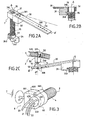
- the cables constituting the bundle 2 are not strung naked into the fastening means 5. They are previously put into a flexible sheath 4, for example made of plastic, of the "accordion" type. This sheath 4 accompanies the cables of the bundle 2 over a determined length l from the arm of the automaton 7, as will be shown later with reference more particularly to FIG. 4.
- a fastener 6 is provided from this end to the automaton 7.
- the fixing member 6 comprises a ring 60, preferably double: two receptacles, 600 and 601 joined by a locking / unlocking member 602, for example screw.
- This ring 60 traps an organ, which will be called "nut” 63, pierced through by channels, 630 to 632 in the example described.
- the material constituting the "nut” 63 is a flexible material, for example plastic, so as to hold the cables, 20 to 22, without hurting them.
- the ring 60 comprises fixing means 61 to an appropriate zone of the automaton 7.
- the automaton 7 consists more particularly of a device called a manipulator.
- the complete system further comprises a control apparatus (not shown) from which the cables forming the beam 2 depart.
- the manipulator 7 comprises an articulated arm 70 having two series of members interconnected, 71 and 72.
- the free end of the arm 72 is provided with a tool holder 720 intended, for example, to receive welding tongs (no shown).
- the assembly rests on a fixed frame 74.
- the bundle 2 in its sheath 4 enters the arm 70 by the end of the arm 72 close to a hinge zone 721 between the two members 71 and 72.
- the device 3 is disposed in the upper part of the manipulator 7, in an area of the member 72 close to the hinge 721.
- the device 3 accompanies these movements and guides and effectively supports the beam 2 in its sheath 4, one of the ends thereof being trapped in the member 72.
- the other end in a preferred embodiment variant, is secured, thanks to the fastening means 6, to the automaton, advantageously at the end of the member 72.
- the exact position of the device 3 (and its axis of rotation ⁇ ) and the length of the deflection arm 30 are determined according to various parameters which depend on the intended application, in particular the dimensions of the components of the arm 70 and the degree of rotation to obtain, so that, whatever the relative positions of the two series of members 71 and 72, one obtains the desired maintenance and guiding of the beam.
- the stiffness of the spring is determined according to the geometric and other parameters associated with the beam 2 (own beam stiffness, mass, etc.).
- the device according to the invention can find application for any automaton comprising moving parts powered by energy supply beam elements, both electrical and fluidic, as has been recalled.
Landscapes
- Engineering & Computer Science (AREA)
- Robotics (AREA)
- Mechanical Engineering (AREA)
- Manipulator (AREA)
- Resistance Welding (AREA)
- Welding Or Cutting Using Electron Beams (AREA)
- Electric Cable Arrangement Between Relatively Moving Parts (AREA)
Claims (10)
- Vorrichtung zum Halten von Elementen eines Energie zuführenden Kabelbündels eines Automaten, umfassend wenigstens ein bewegliches Teil, das mit besagtem Kabelbündel verbunden ist, wobei diese Vorrichtung wenigstens einen so genannten Rückstellarm (3) umfasst, der wenigstens ein Element (20-22) besagten Kabelbündels (2) trägt,
dadurch gekennzeichnet, dass ein erstes Ende besagten Rückstellarms (30) um ein erstes Ende einer Achse (32) gemäß einer ersten Achse (Δ) drehbar ist, dadurch, dass besagte Achse (32) fest gemacht ist an einem zweiten Ende an einem ersten Fixierungsorgan (33, 34), das verbunden ist mit besagtem beweglichen Teil (72), dadurch, dass besagte Achse (32) kombiniert ist mit Mitteln zur Federung (35), die auf besagten Rückstellarm (30) eine Rückholkraft in Richtung auf eine bestimmte Position im Raum (Δ'), Ruhestellung genannt, bezogen auf besagte Achse (32), ausüben, so dass ein Halten und ein Führen besagten Elements bei den Bewegungen im Raum von besagtem beweglichen Teil erzielt werden. - Vorrichtung gemäß Anspruch 1, dadurch gekennzeichnet, dass besagte Mittel, die eine Feder bilden, aus einer Schraubenfeder (35) bestehen, in die hinein besagte Achse (32) eingeführt ist, dadurch, dass besagte Schraubenfeder (35) einen Zapfen (350), der an einem Trägerblock (31) besagten Rückstellarms (30) fest gemacht ist, umfasst und an einem zweiten Ende mit besagtem ersten Fixierungsorgan (33-34) verbunden ist, dadurch, dass besagter Trägerblock (31) ein Wälzlagerorgan (36) umfasst, das besagte Drehung der Achse (32) um die erste Achse (Δ) herum ermöglicht, und dadurch, dass besagter Zapfen (350) über besagten Trägerblock (31) besagte Rückholkraft auf besagten Rückstellarm (30) ausübt, wenn dieser sich von besagter Ruhestellung entfernt (α).
- Vorrichtung gemäß Anspruch 1, dadurch gekennzeichnet, dass besagter Rückstellarm (30) an einem zweiten Ende mit Mitteln zum Befestigen (5) besagten Kabelbündels (2) ausgestattet ist, die aus zwei Halbschalen (530, 531) bestehen, in die dieses Kabelbündel (2) eingeführt wird, und dadurch, dass diese Halbschalen (530, 531) mit Mittel zum Verriegeln/Entriegeln (532) ausgestattet sind.
- Vorrichtung gemäß Anspruch 3, dadurch gekennzeichnet, dass besagte Mittel zum Befestigen (5) eine Achse (51) und Mittel zum Fixieren (52) an besagten Rückstellarm (30) umfassen, und dadurch, dass besagte Halbschalen (530, 531) um besagte Achse (51) herum gemäß einer zweiten Drehachse (Δ") drehbar sind.
- Vorrichtung gemäß einem der vorhergehenden Ansprüche, dadurch gekennzeichnet, dass besagtes Kabelbündel (2) in eine flexible Umhüllung (4) über eine bestimmte Länge (t) ausgehend von einem der besagten beweglichen Teile (72) von besagtem Automaten (7) eingeführt ist.
- Vorrichtung gemäß Anspruch 5, dadurch gekennzeichnet, dass das Ende besagter Umhüllung (4), das besagtem beweglichem Teil (72) gegenüber liegt, mit einem zweiten Organ zur Fixierung (6) an eines der besagten beweglichen Teile (72) von besagtem Automaten (7) ausgestattet ist.
- Vorrichtung gemäß Anspruch 6, dadurch gekennzeichnet, dass besagtes zweites Fixierungsorgan (6) einen Ring (60) umfasst, der ein Halteorgan (63) umschließt, das Kanäle (630-632) umfasst, in die die Elemente (20-22) besagten Bündels (2) ganz oder teilweise eingeführt sind.
- Vorrichtung gemäß einem der vorhergehenden Ansprüche, dadurch gekennzeichnet, dass besagte Elemente flexible Kabel (20-22) sind, die eine elektrische Energie befördern.
- Vorrichtung gemäß einem der vorhergehenden Ansprüche, dadurch gekennzeichnet, dass besagte Elemente flexible Leitungen sind, die eine flüssige Energie befördern.
- Anwendung einer Vorrichtung gemäß einem der vorhergehenden Ansprüche in einem Schweißroboter (1) für die Automobilindustrie.
Applications Claiming Priority (2)
| Application Number | Priority Date | Filing Date | Title |
|---|---|---|---|
| FR0110804A FR2828655B1 (fr) | 2001-08-14 | 2001-08-14 | Dispositif de maintien d'elements de faisceau de transport d'energie a un automate et son application a un robot de soudage |
| FR0110804 | 2001-08-14 |
Publications (2)
| Publication Number | Publication Date |
|---|---|
| EP1284177A1 EP1284177A1 (de) | 2003-02-19 |
| EP1284177B1 true EP1284177B1 (de) | 2006-11-15 |
Family
ID=8866522
Family Applications (1)
| Application Number | Title | Priority Date | Filing Date |
|---|---|---|---|
| EP02291983A Expired - Lifetime EP1284177B1 (de) | 2001-08-14 | 2002-08-07 | Vorrichtung zum Halten eines Energie zuführenden Kabelbündels an einem Schweissroboter |
Country Status (4)
| Country | Link |
|---|---|
| EP (1) | EP1284177B1 (de) |
| AT (1) | ATE345200T1 (de) |
| DE (1) | DE60216019D1 (de) |
| FR (1) | FR2828655B1 (de) |
Cited By (2)
| Publication number | Priority date | Publication date | Assignee | Title |
|---|---|---|---|---|
| EP4169680A1 (de) * | 2021-10-21 | 2023-04-26 | Murrplastik Systemtechnik GmbH | Vorrichtung zur führung von leitungen |
| WO2024056630A1 (de) * | 2022-09-15 | 2024-03-21 | Dürr Systems Ag | Rückstellvorrichtung zum rückstellen zumindest einer leitung |
Family Cites Families (5)
| Publication number | Priority date | Publication date | Assignee | Title |
|---|---|---|---|---|
| DE3434899A1 (de) * | 1983-10-19 | 1985-05-23 | Kuka Schweissanlagen + Roboter Gmbh, 8900 Augsburg | Vorrichtung zum aussenseitigen halten und fuehren von versorgungsleitungen zu bewegten werkzeugen von manipulatoren |
| DE9217659U1 (de) * | 1992-12-24 | 1994-04-07 | Kuka Schweißanlagen + Roboter GmbH, 86165 Augsburg | Leitungsführung für eine Versorgungsleitung an einem mehrachsigen Roboter |
| FR2724866A1 (fr) * | 1994-09-27 | 1996-03-29 | Caty Polymeres Sa | Accastillage universel pour robot industriel |
| DE20010696U1 (de) * | 2000-06-15 | 2001-07-26 | Kuka Roboter GmbH, 86165 Augsburg | Vorrichtung zum Festlegen von Kabeln eines Kabelführungsschlauchs |
| SE0002654D0 (sv) * | 2000-07-14 | 2000-07-14 | Abb Ab | Manipulator |
-
2001
- 2001-08-14 FR FR0110804A patent/FR2828655B1/fr not_active Expired - Fee Related
-
2002
- 2002-08-07 DE DE60216019T patent/DE60216019D1/de not_active Expired - Lifetime
- 2002-08-07 EP EP02291983A patent/EP1284177B1/de not_active Expired - Lifetime
- 2002-08-07 AT AT02291983T patent/ATE345200T1/de not_active IP Right Cessation
Cited By (2)
| Publication number | Priority date | Publication date | Assignee | Title |
|---|---|---|---|---|
| EP4169680A1 (de) * | 2021-10-21 | 2023-04-26 | Murrplastik Systemtechnik GmbH | Vorrichtung zur führung von leitungen |
| WO2024056630A1 (de) * | 2022-09-15 | 2024-03-21 | Dürr Systems Ag | Rückstellvorrichtung zum rückstellen zumindest einer leitung |
Also Published As
| Publication number | Publication date |
|---|---|
| DE60216019D1 (de) | 2006-12-28 |
| ATE345200T1 (de) | 2006-12-15 |
| FR2828655A1 (fr) | 2003-02-21 |
| EP1284177A1 (de) | 2003-02-19 |
| FR2828655B1 (fr) | 2003-11-07 |
Similar Documents
| Publication | Publication Date | Title |
|---|---|---|
| BE898154A (fr) | Manipuleur pour positionner des pièces à usiner ou d'autres charges. | |
| EP3962816A1 (de) | Vorrichtung zur dämpfung des andockens an einen satelliten | |
| EP0388293A1 (de) | Treibriemenspanner | |
| FR2671752A1 (fr) | Systeme actionneur de pinces pour un cadre de fixation supporte par un convoyeur. | |
| EP1370388A1 (de) | Vorrichtung zum antreiben und damit hergestelltes spannwerkeug | |
| EP1284177B1 (de) | Vorrichtung zum Halten eines Energie zuführenden Kabelbündels an einem Schweissroboter | |
| EP0292378A1 (de) | Vorrichtung zum Lagern von Objekten | |
| CH456450A (fr) | Installation pour effecteur des opérations sur des objets en des postes de stationnement momentanés comprenant un appareillage de transfert de ces objets | |
| FR2670424A1 (fr) | Dispositif manipulateur pour deplacer un objet, dans l'espace, parallelement a lui-meme. | |
| EP1304195A1 (de) | Haltevorrichtung für einen zu einem Automaten Energie zuleitende Kabelbaum und ihre Anwendung für einen Schweissroboter | |
| EP0109405B1 (de) | Einrichtung zum greifen von gegenständen für manipulator vom robotertyp | |
| FR2498379A1 (fr) | Dispositif d'orientation selon deux axes orthogonaux, utilisation dans une antenne hyperfrequence et antenne hyperfrequence comportant un tel dispositif | |
| FR2662314A1 (fr) | Poignet pour le maintien de cables. | |
| EP0093042A1 (de) | Auto-adaptierende und schwingungsdämpfende Spannvorrichtung | |
| WO2004089578A2 (fr) | Dispositif d'actionnement, notamment pour un bras articule | |
| FR3141363A1 (fr) | Articulation à trois degrés de liberté avec renvoi d’efforts | |
| FR2707912A1 (fr) | Dispositif de préhension fixé au nez d'un robot pour saisir des pièces plates ou peu galbées de véhicule automobile. | |
| FR2581914A1 (fr) | Dispositif de prehension de pieces pour robot manipulateur | |
| EP0190062B1 (de) | Einstellbarer Träger für einen Richtspiegel eines Scheinwerfers | |
| EP3546141A1 (de) | Vorrichtung mit kabeln für die anwendung von gleichen kräften an mindestens zwei von einander entfernten punkten | |
| WO2013076141A1 (fr) | Dispositif mobile dans un champ magnetique ambiant de grande intensite | |
| EP1364904A1 (de) | Verschiebungsvorrichtung für Aufzugskabine | |
| FR2692514A1 (fr) | Dispositif formant interface mécanique souple interposée entre le poignet d'un robot et un outil de travail de celui-ci. | |
| EP0647508A1 (de) | Vorrichtung zum Einbau eines Sitzes in die Karosserie eines Automobils | |
| EP0549453A1 (de) | Mechanische Interfaceeinrichtung angeordnet zwischen dem Ende eines Roboters und einem Roboterwerkzeug |
Legal Events
| Date | Code | Title | Description |
|---|---|---|---|
| PUAI | Public reference made under article 153(3) epc to a published international application that has entered the european phase |
Free format text: ORIGINAL CODE: 0009012 |
|
| AK | Designated contracting states |
Designated state(s): AT BE BG CH CY CZ DE DK EE ES FI FR GB GR IE IT LI LU MC NL PT SE SK TR |
|
| AX | Request for extension of the european patent |
Extension state: AL LT LV MK RO SI |
|
| 17P | Request for examination filed |
Effective date: 20030527 |
|
| AKX | Designation fees paid |
Designated state(s): AT BE BG CH CY CZ DE DK EE ES FI FR GB GR IE IT LI LU MC NL PT SE SK TR |
|
| GRAP | Despatch of communication of intention to grant a patent |
Free format text: ORIGINAL CODE: EPIDOSNIGR1 |
|
| GRAS | Grant fee paid |
Free format text: ORIGINAL CODE: EPIDOSNIGR3 |
|
| GRAA | (expected) grant |
Free format text: ORIGINAL CODE: 0009210 |
|
| AK | Designated contracting states |
Kind code of ref document: B1 Designated state(s): AT BE BG CH CY CZ DE DK EE ES FI FR GB GR IE IT LI LU MC NL PT SE SK TR |
|
| PG25 | Lapsed in a contracting state [announced via postgrant information from national office to epo] |
Ref country code: IT Free format text: LAPSE BECAUSE OF FAILURE TO SUBMIT A TRANSLATION OF THE DESCRIPTION OR TO PAY THE FEE WITHIN THE PRESCRIBED TIME-LIMIT;WARNING: LAPSES OF ITALIAN PATENTS WITH EFFECTIVE DATE BEFORE 2007 MAY HAVE OCCURRED AT ANY TIME BEFORE 2007. THE CORRECT EFFECTIVE DATE MAY BE DIFFERENT FROM THE ONE RECORDED. Effective date: 20061115 Ref country code: FI Free format text: LAPSE BECAUSE OF FAILURE TO SUBMIT A TRANSLATION OF THE DESCRIPTION OR TO PAY THE FEE WITHIN THE PRESCRIBED TIME-LIMIT Effective date: 20061115 Ref country code: SK Free format text: LAPSE BECAUSE OF FAILURE TO SUBMIT A TRANSLATION OF THE DESCRIPTION OR TO PAY THE FEE WITHIN THE PRESCRIBED TIME-LIMIT Effective date: 20061115 Ref country code: NL Free format text: LAPSE BECAUSE OF FAILURE TO SUBMIT A TRANSLATION OF THE DESCRIPTION OR TO PAY THE FEE WITHIN THE PRESCRIBED TIME-LIMIT Effective date: 20061115 Ref country code: CZ Free format text: LAPSE BECAUSE OF FAILURE TO SUBMIT A TRANSLATION OF THE DESCRIPTION OR TO PAY THE FEE WITHIN THE PRESCRIBED TIME-LIMIT Effective date: 20061115 Ref country code: AT Free format text: LAPSE BECAUSE OF FAILURE TO SUBMIT A TRANSLATION OF THE DESCRIPTION OR TO PAY THE FEE WITHIN THE PRESCRIBED TIME-LIMIT Effective date: 20061115 Ref country code: IE Free format text: LAPSE BECAUSE OF FAILURE TO SUBMIT A TRANSLATION OF THE DESCRIPTION OR TO PAY THE FEE WITHIN THE PRESCRIBED TIME-LIMIT Effective date: 20061115 |
|
| REG | Reference to a national code |
Ref country code: GB Ref legal event code: FG4D Free format text: NOT ENGLISH |
|
| REG | Reference to a national code |
Ref country code: CH Ref legal event code: EP |
|
| REF | Corresponds to: |
Ref document number: 60216019 Country of ref document: DE Date of ref document: 20061228 Kind code of ref document: P |
|
| REG | Reference to a national code |
Ref country code: IE Ref legal event code: FG4D Free format text: LANGUAGE OF EP DOCUMENT: FRENCH |
|
| PG25 | Lapsed in a contracting state [announced via postgrant information from national office to epo] |
Ref country code: BG Free format text: LAPSE BECAUSE OF FAILURE TO SUBMIT A TRANSLATION OF THE DESCRIPTION OR TO PAY THE FEE WITHIN THE PRESCRIBED TIME-LIMIT Effective date: 20070215 Ref country code: DK Free format text: LAPSE BECAUSE OF FAILURE TO SUBMIT A TRANSLATION OF THE DESCRIPTION OR TO PAY THE FEE WITHIN THE PRESCRIBED TIME-LIMIT Effective date: 20070215 Ref country code: SE Free format text: LAPSE BECAUSE OF FAILURE TO SUBMIT A TRANSLATION OF THE DESCRIPTION OR TO PAY THE FEE WITHIN THE PRESCRIBED TIME-LIMIT Effective date: 20070215 |
|
| PG25 | Lapsed in a contracting state [announced via postgrant information from national office to epo] |
Ref country code: DE Free format text: LAPSE BECAUSE OF FAILURE TO SUBMIT A TRANSLATION OF THE DESCRIPTION OR TO PAY THE FEE WITHIN THE PRESCRIBED TIME-LIMIT Effective date: 20070216 |
|
| PG25 | Lapsed in a contracting state [announced via postgrant information from national office to epo] |
Ref country code: ES Free format text: LAPSE BECAUSE OF FAILURE TO SUBMIT A TRANSLATION OF THE DESCRIPTION OR TO PAY THE FEE WITHIN THE PRESCRIBED TIME-LIMIT Effective date: 20070226 |
|
| PG25 | Lapsed in a contracting state [announced via postgrant information from national office to epo] |
Ref country code: PT Free format text: LAPSE BECAUSE OF FAILURE TO SUBMIT A TRANSLATION OF THE DESCRIPTION OR TO PAY THE FEE WITHIN THE PRESCRIBED TIME-LIMIT Effective date: 20070416 |
|
| NLV1 | Nl: lapsed or annulled due to failure to fulfill the requirements of art. 29p and 29m of the patents act | ||
| GBV | Gb: ep patent (uk) treated as always having been void in accordance with gb section 77(7)/1977 [no translation filed] |
Effective date: 20061115 |
|
| REG | Reference to a national code |
Ref country code: IE Ref legal event code: FD4D |
|
| PLBE | No opposition filed within time limit |
Free format text: ORIGINAL CODE: 0009261 |
|
| STAA | Information on the status of an ep patent application or granted ep patent |
Free format text: STATUS: NO OPPOSITION FILED WITHIN TIME LIMIT |
|
| 26N | No opposition filed |
Effective date: 20070817 |
|
| PG25 | Lapsed in a contracting state [announced via postgrant information from national office to epo] |
Ref country code: GB Free format text: LAPSE BECAUSE OF FAILURE TO SUBMIT A TRANSLATION OF THE DESCRIPTION OR TO PAY THE FEE WITHIN THE PRESCRIBED TIME-LIMIT Effective date: 20061115 |
|
| BERE | Be: lapsed |
Owner name: CIMLEC INDUSTRIE Effective date: 20070831 |
|
| REG | Reference to a national code |
Ref country code: CH Ref legal event code: PL |
|
| PG25 | Lapsed in a contracting state [announced via postgrant information from national office to epo] |
Ref country code: GR Free format text: LAPSE BECAUSE OF FAILURE TO SUBMIT A TRANSLATION OF THE DESCRIPTION OR TO PAY THE FEE WITHIN THE PRESCRIBED TIME-LIMIT Effective date: 20070216 Ref country code: CH Free format text: LAPSE BECAUSE OF NON-PAYMENT OF DUE FEES Effective date: 20070831 Ref country code: LI Free format text: LAPSE BECAUSE OF NON-PAYMENT OF DUE FEES Effective date: 20070831 Ref country code: MC Free format text: LAPSE BECAUSE OF NON-PAYMENT OF DUE FEES Effective date: 20070831 |
|
| REG | Reference to a national code |
Ref country code: FR Ref legal event code: ST Effective date: 20080430 |
|
| PG25 | Lapsed in a contracting state [announced via postgrant information from national office to epo] |
Ref country code: BE Free format text: LAPSE BECAUSE OF NON-PAYMENT OF DUE FEES Effective date: 20070831 |
|
| PG25 | Lapsed in a contracting state [announced via postgrant information from national office to epo] |
Ref country code: FR Free format text: LAPSE BECAUSE OF NON-PAYMENT OF DUE FEES Effective date: 20070831 |
|
| PG25 | Lapsed in a contracting state [announced via postgrant information from national office to epo] |
Ref country code: EE Free format text: LAPSE BECAUSE OF FAILURE TO SUBMIT A TRANSLATION OF THE DESCRIPTION OR TO PAY THE FEE WITHIN THE PRESCRIBED TIME-LIMIT Effective date: 20061115 |
|
| PG25 | Lapsed in a contracting state [announced via postgrant information from national office to epo] |
Ref country code: LU Free format text: LAPSE BECAUSE OF NON-PAYMENT OF DUE FEES Effective date: 20070807 Ref country code: CY Free format text: LAPSE BECAUSE OF FAILURE TO SUBMIT A TRANSLATION OF THE DESCRIPTION OR TO PAY THE FEE WITHIN THE PRESCRIBED TIME-LIMIT Effective date: 20061115 |
|
| PG25 | Lapsed in a contracting state [announced via postgrant information from national office to epo] |
Ref country code: TR Free format text: LAPSE BECAUSE OF FAILURE TO SUBMIT A TRANSLATION OF THE DESCRIPTION OR TO PAY THE FEE WITHIN THE PRESCRIBED TIME-LIMIT Effective date: 20061115 |