EP1285636B1 - Appareil séparateur - Google Patents
Appareil séparateur Download PDFInfo
- Publication number
- EP1285636B1 EP1285636B1 EP02015401A EP02015401A EP1285636B1 EP 1285636 B1 EP1285636 B1 EP 1285636B1 EP 02015401 A EP02015401 A EP 02015401A EP 02015401 A EP02015401 A EP 02015401A EP 1285636 B1 EP1285636 B1 EP 1285636B1
- Authority
- EP
- European Patent Office
- Prior art keywords
- separator unit
- modular system
- solid
- rotor
- liquid
- Prior art date
- Legal status (The legal status is an assumption and is not a legal conclusion. Google has not performed a legal analysis and makes no representation as to the accuracy of the status listed.)
- Expired - Lifetime
Links
- 239000007788 liquid Substances 0.000 claims abstract description 71
- 239000007787 solid Substances 0.000 claims abstract description 32
- 230000002093 peripheral effect Effects 0.000 claims description 13
- 230000000295 complement effect Effects 0.000 claims description 3
- 238000001746 injection moulding Methods 0.000 claims description 2
- 239000000945 filler Substances 0.000 claims 2
- 239000013589 supplement Substances 0.000 claims 1
- 238000000926 separation method Methods 0.000 description 56
- XLYOFNOQVPJJNP-UHFFFAOYSA-N water Substances O XLYOFNOQVPJJNP-UHFFFAOYSA-N 0.000 description 16
- 239000002245 particle Substances 0.000 description 13
- 239000000203 mixture Substances 0.000 description 10
- 230000008021 deposition Effects 0.000 description 8
- 238000011161 development Methods 0.000 description 7
- 230000018109 developmental process Effects 0.000 description 7
- 239000013049 sediment Substances 0.000 description 7
- 239000002351 wastewater Substances 0.000 description 5
- 239000012530 fluid Substances 0.000 description 3
- 238000002347 injection Methods 0.000 description 3
- 239000007924 injection Substances 0.000 description 3
- 238000009434 installation Methods 0.000 description 3
- 238000005192 partition Methods 0.000 description 3
- 239000000047 product Substances 0.000 description 3
- 238000013022 venting Methods 0.000 description 3
- 230000001914 calming effect Effects 0.000 description 2
- 238000010276 construction Methods 0.000 description 2
- 238000004519 manufacturing process Methods 0.000 description 2
- 230000000717 retained effect Effects 0.000 description 2
- 238000007789 sealing Methods 0.000 description 2
- 230000000007 visual effect Effects 0.000 description 2
- 230000000712 assembly Effects 0.000 description 1
- 238000000429 assembly Methods 0.000 description 1
- 230000005540 biological transmission Effects 0.000 description 1
- 230000000903 blocking effect Effects 0.000 description 1
- 239000000470 constituent Substances 0.000 description 1
- 230000007797 corrosion Effects 0.000 description 1
- 238000005260 corrosion Methods 0.000 description 1
- 238000005553 drilling Methods 0.000 description 1
- 239000013536 elastomeric material Substances 0.000 description 1
- 230000008030 elimination Effects 0.000 description 1
- 238000003379 elimination reaction Methods 0.000 description 1
- 230000002349 favourable effect Effects 0.000 description 1
- 230000014759 maintenance of location Effects 0.000 description 1
- 230000007257 malfunction Effects 0.000 description 1
- 230000002035 prolonged effect Effects 0.000 description 1
- 230000001681 protective effect Effects 0.000 description 1
- 238000005086 pumping Methods 0.000 description 1
- 239000008213 purified water Substances 0.000 description 1
- 230000000630 rising effect Effects 0.000 description 1
- 238000004062 sedimentation Methods 0.000 description 1
- 239000002002 slurry Substances 0.000 description 1
- 239000007921 spray Substances 0.000 description 1
- 239000006228 supernatant Substances 0.000 description 1
- 231100000331 toxic Toxicity 0.000 description 1
- 230000002588 toxic effect Effects 0.000 description 1
- 238000009423 ventilation Methods 0.000 description 1
Images


Classifications
-
- B—PERFORMING OPERATIONS; TRANSPORTING
- B04—CENTRIFUGAL APPARATUS OR MACHINES FOR CARRYING-OUT PHYSICAL OR CHEMICAL PROCESSES
- B04B—CENTRIFUGES
- B04B9/00—Drives specially designed for centrifuges; Arrangement or disposition of transmission gearing; Suspending or balancing rotary bowls
- B04B9/12—Suspending rotary bowls ; Bearings; Packings for bearings
-
- A—HUMAN NECESSITIES
- A61—MEDICAL OR VETERINARY SCIENCE; HYGIENE
- A61C—DENTISTRY; APPARATUS OR METHODS FOR ORAL OR DENTAL HYGIENE
- A61C17/00—Devices for cleaning, polishing, rinsing or drying teeth, teeth cavities or prostheses; Saliva removers; Dental appliances for receiving spittle
- A61C17/06—Saliva removers; Accessories therefor
- A61C17/065—Saliva removers; Accessories therefor characterised by provisions for processing the collected matter, e.g. for separating solids or air
-
- B—PERFORMING OPERATIONS; TRANSPORTING
- B01—PHYSICAL OR CHEMICAL PROCESSES OR APPARATUS IN GENERAL
- B01D—SEPARATION
- B01D19/00—Degasification of liquids
- B01D19/0042—Degasification of liquids modifying the liquid flow
- B01D19/0052—Degasification of liquids modifying the liquid flow in rotating vessels, vessels containing movable parts or in which centrifugal movement is caused
-
- B—PERFORMING OPERATIONS; TRANSPORTING
- B04—CENTRIFUGAL APPARATUS OR MACHINES FOR CARRYING-OUT PHYSICAL OR CHEMICAL PROCESSES
- B04B—CENTRIFUGES
- B04B1/00—Centrifuges with rotary bowls provided with solid jackets for separating predominantly liquid mixtures with or without solid particles
- B04B1/02—Centrifuges with rotary bowls provided with solid jackets for separating predominantly liquid mixtures with or without solid particles without inserted separating walls
-
- B—PERFORMING OPERATIONS; TRANSPORTING
- B04—CENTRIFUGAL APPARATUS OR MACHINES FOR CARRYING-OUT PHYSICAL OR CHEMICAL PROCESSES
- B04B—CENTRIFUGES
- B04B7/00—Elements of centrifuges
- B04B7/02—Casings; Lids
-
- B—PERFORMING OPERATIONS; TRANSPORTING
- B01—PHYSICAL OR CHEMICAL PROCESSES OR APPARATUS IN GENERAL
- B01D—SEPARATION
- B01D2221/00—Applications of separation devices
- B01D2221/10—Separation devices for use in medical, pharmaceutical or laboratory applications, e.g. separating amalgam from dental treatment residues
Definitions
- the invention relates to a modular system for a separator.
- a corresponding separator may e.g. DE 30 30 614 A1 are taken.
- Such a solid-state separator comprises a centrifuge drum driven by a drive motor, which separates solid particles from the dental wastewater.
- combined separation devices are also known which retain both liquid fractions and solid fractions from the mixture of air / liquid / solid particles obtained at a dental workstation.
- Such combined deposition devices can, for example, the structure described in DE 35 21 929 A1 to have.
- a construction of a modular system is to be specified, which allows the assembly of deposition devices, which can deposit only liquid, only solid particles or liquid and solid particles, using as much as possible the same components.
- one has the same or at least similar abutment surfaces between a support plate, on which also the drive motor is arranged, and an air separation unit or a solid-state separation unit. These units can thus be optionally mounted on the support plate.
- the invention brings a significant cost savings in the production, since you can produce the common components in larger quantities for the different product lines.
- the manufacturer is more flexible in production planning because he can use the same components either for each of the product lines.
- a modular system can comprise both a liquid-separating unit and a solid-state separation unit.
- An adapter part as indicated in claim 4, has mechanically particularly simple structure.
- Claim 7 indicates a special bottom part, which is used when the device only has an air separation unit.
- This non-standard part has simple geometry. It can also be obtained by modifying an injection molding tool for such a bottom part which is used in an air separation unit which is used together with a solid-state separation unit and has a central shaft passage opening.
- a modular system according to claim 8 can be obtained by simple plug connection of partial waves driving the rotors of liquid separation unit and solid-state separation unit.
- the drive shaft thus has a similar modular construction as the housing of the separation units.
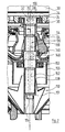
- a total of 10 denotes a combined separating device, which has an inlet connection 12, which is connected under operating conditions with the Saugablage a dental workstation and is connected there to a suction cannula, via which a mixture of air, liquid and formed during drilling fine solid particles, in particular Amalgampumblen, is sucked out of the mouth of a patient.
- an outlet 14 of the KombiAbborgeologis is connected under conditions of use with a not shown in the drawing suction machine, which may be, for example, a side channel machine.
- the discharged at the outlet port 14 air is free of liquid fractions, and similar liquid fractions, which are discharged at a further outlet port 16 of the combination separator 10, freed from solid fractions.
- the combination separator 10 comprises, in addition to a drive unit designated overall by 18, a liquid separation unit designated as a whole by 20, and a solid-state deposition unit designated overall by 22.
- the drive unit 18 comprises a support plate 24 which is attached via buttoned double-conical vibration damper 26 made of elastomeric material to a mounting plate 28, which in turn is connected to a not shown in the drawing device frame, which is connected to a supporting part of the dental workstation or on the Floor of the practice room is set up.
- the support plate 24 carries on top of an electric drive motor 30 with a downwardly projecting motor shaft 32.
- the latter extends through a central Opening 34 of the support plate 24 and is sealed against this by a lip seal 36.
- the liquid separation unit 20 has a housing part 38, which is fitted with an upper cylindrical portion 40 in an edge shoulder 42 of the support plate 24 and is sealed against the support plate by an O-ring 44.
- the upper housing portion 40 communicates with the outlet port 14 in connection.
- a lower likewise cylindrical housing portion 48 of the housing part 38 receives a bottom part 50 and is sealed against this by an O-ring 52.
- the bottom part 50 is, as shown in the drawing frusto-conical and lies with little play under the lower end face of a rotor generally designated 54.
- the latter has a frustoconical lower rotor wall 56 which is occupied by pump blades 58.
- a contoured peripheral wall 60 of the rotor 54 is connected to a hub portion 64 of the rotor 54 via three circumferentially distributed vanes 62.
- a drive shaft 66 of the liquid separation unit 20 is injected.
- the upper housing portion 40 carries on a transverse partition wall 68, a sealing member 70 which is guided from above under play in the upper end of the peripheral wall 60.
- a radial flange 72 which is provided at the upper end of the outer side of the peripheral wall 60, carries small sealing wings 73. The aforementioned parts form a dynamic Seal at the upper end of the rotor 54.
- a helical guide rib 74 returns fluid retained by the dynamic seal to the interior of the fluid separation unit 20.
- the mixture sucked in via the inlet connection 12 is listed tangentially on the inner surface of the peripheral wall 60 and arrives downwardly in a helical way into the working area of the pumping vanes 58.
- the drive shaft 66 has (see Figure 2) at the upper end a drive square 76 which cooperates with a corresponding square recess 78 in the end of the motor shaft 32.
- the liquid separation unit 20 operates as follows: When the drive motor 30 is running, the sucked mixture is given a spin by the pump vanes 58. By centrifugal action, the liquid portions of the mixture are moved outwardly and forced by the pump vanes 58 into a liquid outlet port 80 ( Figures 7 and 8) of the liquid separation unit 20.
- FIG. 5 illustrates a valve seat for a flutter valve body 82 clamped between the fluid outlet port 80 and a first inlet port 84 of a branch piece 86.
- the branch piece 86 has a second inlet port 88, which is shown closed in Figure 7 by a cap 90, but can be connected under conditions of use with the outlet of a cuspidor.
- a siphon 92 is provided in Figure 8 right of the flutter valve body 82, which holds a volume of water under operating conditions, which acts on the flutter valve body 82 from the right.
- the flutter valve body 82 is additionally acted upon by the vacuum prevailing in the interior of the liquid separation unit 20. Only when a larger volume of deposited liquid has accumulated in the lower portion of the liquid separation unit can the pump vanes 58 move the licker-up valve body 82 to overcome the pressure differential in the open position such that a portion of separated liquid enters the branch piece 86.
- a guide wall 94 is arranged above this, which transversely overlaps the siphon wall, but is axially spaced therefrom.
- the guide wall 94 is integrally formed on an intermediate part 96, which is placed on the second inlet port 88.
- An outlet port 98 of the branch piece 86 is connected to a manifold 100, which leads via a further T-piece 102 ( Figure 4) and another manifold 104 to an inlet port 106 of the solid-state separation unit, which is particularly apparent from Figure 5.
- the upwardly facing connecting piece of the T-piece 102 provides another way to connect a wastewater source, possibly an alternative way to branch piece 86 for connecting the cuspidor.
- the upper connection piece of the T-piece 102 is closed by a cap 90.
- the solid-state separation unit 22 has a housing 108 which surrounds a rotor 110, designated as a whole by 110, which is designed as a centrifuge drum.
- An upper cylindrical end portion of the housing 108 is sealed by an O-ring 112 inserted into a cylindrical connecting wall 114, which is integrally formed on the bottom part 50 of the liquid separation unit 20.
- a lower connecting wall 116 of the housing 108 is formed via a transverse partition wall 118 to a conical wall portion 120 of the housing 108.
- the connecting wall 116 carries two O-rings 122, 124, via which a seal to a retaining ring 126 and an upper edge 128 of a solid-state collecting container 130 takes place. The latter is attached via a bayonet lock on the connecting wall 116, which need not be described in more detail here.
- the conical wall section 120 of the housing 108 carries in the circumferential direction three calming wings 132, which project down into the collecting container 130.
- the rotor 112 has a cylindrical peripheral wall 134, in the upper end of a locking flange 135 is inserted. At the lower end of the peripheral wall 134, a frusto-conical wall portion 136 is formed, which hineinerstreckt up to a height h in the interior of the collecting container 130.
- the wall portion 136 is connected to a hub portion 138 via four circumferentially distributed radial blades 137.
- a drive shaft 140 is injected, which is provided at its upper end with a drive square 146 (see Fig. 2) which engages positively in a complementary recess 148 which is provided in the lower end of the drive shaft 66 of the diesstechniksabscheideisme 20.
- the drive shafts 66 and 140 each have a through hole 150 and 152, and through these aligned through holes extending a fastening screw 154 whose upper end in Figure 2 cooperates with a threaded bore 156 which is provided in the lower end of the motor shaft 32. Between the head of the fastening screw 154 and the lower end of the hub portion 138, a washer 151 is provided. In this way, the two rotors 54 and 110 of the two separation units 20, 22 are fixedly connected to the motor shaft 32 for common rotation.
- the upper end of the drive shaft 140 is sealed against the bottom part 50 by a lip seal 153.
- a cylindrical bulkhead 155 formed, which dips into the interior of the centrifuge drum.
- a total of 160 designated float is arranged inside the bounded by the collecting container 130 and the lower portion 118, 122 of the housing 108 .
- This consists of two tightly welded half shells 162, 164 and carries a permanent magnet 166 which is magnetized in relation to the device axis radial direction.
- the permanent magnet 166 cooperates with three differently arranged magnetic field sensors 168, 170 and 172, which may be formed by read switches or Hall sensors.
- the float 160 is axially movably supported by the outer edges of the calming wings 132, for which purpose they are provided with an edge recess 174. In this way, the float 160 is movable but stored captive.
- the inlet nozzle 106 opens tangentially into the space which is bounded by the lower portion of the housing 108 and the collecting container 130.
- the supplied liquid thus revolves on the inner surface of the peripheral wall enclosing this space down past the float 160.
- the solid-state deposition unit 22 described above operates as follows:
- Containing solid particles wastewater which is supplied either from the liquid separation unit 20 or from the cuspidor of the workplace fro the branch piece 86, flows through the inlet port 106 into the interior of the housing 108 and into the collecting container 130th
- the float 160 rises.
- the field of the permanent magnet 166 reaches the uppermost magenta field sensor 172, it sends a corresponding signal to a control unit 176.
- This sets the drive motor 30 in motion.
- the rotor 110 is thus accelerated to high speed (typically 2 500 to 10 000 rpm), and the conical wall portion 136 of the rotor 110 now sucks water from the upper portion of the sump 130 until the water level reaches the lower edge of the wall portion 136 has reached.
- a switch 178 is provided, which is arranged in the Saugkanülenablage the workplace and cooperates with the suction cannula.
- the switch 178 is closed and the drive motor 30 is energized by the control unit 176 connected to the switch 178.
- the extracted from the mouth mixture of air / liquid / solid particles first passes into the liquid separation unit 20, where liquid and solid particles are separated from the air.
- the air leaves the liquid separation unit 20 via the outlet port 14, the solid particles containing liquid portion of the mixture is supplied via the outlet port 80 and the branch piece 86 to the inlet port 106 of the solid-state separation unit.
- the drive motor 30 is stopped. After elimination of the centrifugal force, the slurry retained in the centrifuge drum flows downwardly through the opening in the conical wall section 136 into the sedimentation vessel 130, where the level increases accordingly. The heavy solid particles settle in the collecting container 130. When removing the suction cannula from the tray, the cycle described above is repeated.
- the permanent magnet 166 finally actuates the magnetic field sensor 170. This corresponds to the maximum permissible sediment level in the collection container 130.
- the control unit 176 can now produce a sharper visual and / or audible alarm or, if desired, also bring about an emergency stop of the separator.
- the above unit decomposes the mixture of air / water / solid particles obtained at the dental workstation into its components and, on the one hand, the suction machine against liquid portions, and on the other hand the sewer system protects against toxic solid components.
- the venting device 180 includes a vent opening 182 provided in the horizontal wall portion 118 of the housing 108.
- the vent opening 184 is closable by a valve body 182, which is shown as a double lip ring.
- the valve body 184 is unbuttoned on a support bar 186 which is supported by a control lever 188.
- the latter has a cylindrical bearing rib 190, which is rotatably mounted in a complementary bearing recess 192 of the housing.
- a curved contact head 192 is provided which lies in the path of the float 160.
- a stop arm 194 of the actuating lever 188 in cooperation with an adjacent housing surface, a lower horizontal end position of the valve body 184 before, which is shown in the drawing.
- a separator it is not necessary for a separator to include both a liquid separation unit and a solid state separation unit. Examples are installations in which a cyclone is already present as a liquid separator and only a solid-state separation is desired. Conversely, a solid-state separator can already be provided at a workstation, and it is only desired to replace the already existing cyclone liquid separator by a motor-driven liquid separator.
- the solid-state deposition unit 22 can also be attached directly to the drive unit 18.
- an adapter part 196 is now placed instead of the bottom part 50 of the liquid separation unit 20, which has the same diameter as the upper housing portion 40 of the housing part 38.
- the adapter part 196 has a purely cylindrical peripheral wall 198.
- a transverse partition 200 is formed at such axial location that it lies over the underside of the support plate 24.
- the intermediate wall 200 carries the protective tube 155.
- the separator according to FIG. 12 is a pure liquid separator.
- the liquid separation unit 20 is placed on the underside of the support plate 24, as described below.
- a filling member 202 is inserted, which fills the recess 148 with the exception of a through hole and a recess for the head of a fastening screw.
- the fastening screw 154 is now selected according to the length of the drive shaft 66.
- the bottom part 50 is replaced by a bottom part 204, which is closed at the bottom center, but otherwise the same geometry as the bottom part 50th
Landscapes
- Health & Medical Sciences (AREA)
- Public Health (AREA)
- Chemical & Material Sciences (AREA)
- Life Sciences & Earth Sciences (AREA)
- Animal Behavior & Ethology (AREA)
- General Health & Medical Sciences (AREA)
- Dentistry (AREA)
- Veterinary Medicine (AREA)
- Epidemiology (AREA)
- Chemical Kinetics & Catalysis (AREA)
- Centrifugal Separators (AREA)
- Accommodation For Nursing Or Treatment Tables (AREA)
- Polarising Elements (AREA)
- Sanitary Device For Flush Toilet (AREA)
- Valve Device For Special Equipments (AREA)
Claims (12)
- Système modulaire d'un appareil séparateur comprenant un moteur d'entraînement (30), une plaque support (24) pour le moteur d'entraînement (30), une unité séparatrice de liquide (20) comprenant un rotor et une unité séparatrice de solides (22) comprenant un rotor, la plaque support (24) pour le moteur d'entraînement (30) présentant une géométrie de raccordement telle qu'il est possible de poser directement sur elle aussi bien une paroi terminale de l'unité séparatrice de liquide (20) qu'une paroi terminale de l'unité séparatrice de solides (22).
- Système modulaire d'un appareil séparateur comprenant un moteur d'entraînement (30), une plaque support (24) pour le moteur d'entraînement (30) une pièce adaptatrice (196), une unité séparatrice de liquide (20) comprenant un rotor et une unité séparatrice de solides (22) comprenant un rotor, la plaque support (24) pour le moteur d'entraînement (30) présentant une géométrie de raccordement telle qu'il est possible de poser sur elle, en intercalant la pièce adaptatrice (196), aussi bien une paroi terminale de l'unité séparatrice de liquide (20) qu'une paroi terminale de l'unité séparatrice de solides (22).
- Système modulaire selon la revendication 1 ou 2, caractérisé par le fait qu'une deuxième paroi terminale de l'unité séparatrice de liquide (20) présente une géométrie de raccordement telle qu'une paroi terminale de l'unité séparatrice de solides (22) peut être posée sur elle.
- Système modulaire selon la revendication 2 ou 3, caractérisé par le fait que la pièce adaptatrice (196) est essentiellement en forme de manchon.
- Système modulaire selon la revendication 4, caractérisé par le fait que la pièce adaptatrice en forme de manchon présente des sections terminales de diamètre différent.
- Système modulaire selon l'une des revendications 2 à 5, caractérisé par le fait que la plaque support (24) présente un épaulement (42) s'étendant en direction circonférentielle sur lequel une paroi périphérique (42) d'une pièce de boîtier (38) de l'unité séparatrice de liquide (20), de l'unité séparatrice de solides (22) ou de la pièce adaptatrice (196) est engagée de manière étanche.
- Système modulaire selon l'une des revendications 1 à 6, caractérisé par une pièce de fond (204) pour une unité séparatrice de liquide (20) qui présente une géométrie essentiellement identique à celle d'une pièce de couvercle (50) d'une unité séparatrice de solides (22) mais qui est fermée.
- Système modulaire selon l'une des revendications 1 à 7, caractérisé par le fait qu'un arbre d'entraînement (66) pour le rotor (54) de l'unité séparatrice de liquide (20) et un arbre d'entraînement (140) pour le rotor (110) de l'unité séparatrice de solides (22) présentent à une extrémité des moyens d'emboîtement (76 ; 146) identiques qui sont complémentaires de moyens d'emboîtement (78) dans l'extrémité libre de l'arbre (32) du moteur d'entraînement (30).
- Système modulaire selon la revendication 8, caractérisé par le fait qu'une deuxième extrémité de l'arbre d'entraînement (66) de l'unité séparatrice de liquide (20) présente des moyens d'emboîtement (148) qui sont identiques aux moyens d'emboîtement (78) de l'arbre de moteur (32).
- Système modulaire selon la revendication 8 ou 9, caractérisé par le fait que les arbres d'entraînement (66 ; 140) pour les rotors (54 ; 110) de l'unité séparatrice de liquide (20) et de l'unité séparatrice de solides (22) présentent chacun un trou de passage (150 ; 152) pour un moyen de fixation (154) qui agit sur l'extrémité de l'arbre de moteur (30).
- Système modulaire selon l'une des revendications 8 à 10, caractérisé par le fait qu'au moins un arbre d'entraînement (66 ; 140) des unités séparatrices (20 ; 22) est injecté dans le rotor (54 ; 110) de l'unité séparatrice (20 ; 22) associée.
- Système modulaire selon l'une des revendications 8 à 11, caractérisé par une pièce de remplissage (202) pour l'extrémité libre de l'arbre d'entraînement (66) de l'unité séparatrice de liquide (20), laquelle complète cette extrémité d'arbre en vue d'une symétrie d'arbre totale et présente un trou de passage pour un moyen de fixation (154) et le cas échéant un évidement pour une tête du moyen de fixation (154).
Applications Claiming Priority (2)
| Application Number | Priority Date | Filing Date | Title |
|---|---|---|---|
| DE10139025 | 2001-08-15 | ||
| DE10139025A DE10139025A1 (de) | 2001-08-15 | 2001-08-15 | Abscheidegerät |
Publications (3)
| Publication Number | Publication Date |
|---|---|
| EP1285636A2 EP1285636A2 (fr) | 2003-02-26 |
| EP1285636A3 EP1285636A3 (fr) | 2003-05-21 |
| EP1285636B1 true EP1285636B1 (fr) | 2007-01-03 |
Family
ID=7694844
Family Applications (1)
| Application Number | Title | Priority Date | Filing Date |
|---|---|---|---|
| EP02015401A Expired - Lifetime EP1285636B1 (fr) | 2001-08-15 | 2002-07-11 | Appareil séparateur |
Country Status (5)
| Country | Link |
|---|---|
| EP (1) | EP1285636B1 (fr) |
| JP (1) | JP4275913B2 (fr) |
| AT (1) | ATE349970T1 (fr) |
| DE (2) | DE10139025A1 (fr) |
| ES (1) | ES2278841T3 (fr) |
Families Citing this family (1)
| Publication number | Priority date | Publication date | Assignee | Title |
|---|---|---|---|---|
| AT505538B1 (de) * | 2007-07-27 | 2009-02-15 | Pregenzer Bruno | Abscheider zum abscheiden von luft und feststoffen aus einem zahnärztlichen abwassergemisch |
Family Cites Families (3)
| Publication number | Priority date | Publication date | Assignee | Title |
|---|---|---|---|---|
| SE440071B (sv) | 1979-08-17 | 1985-07-15 | Scania Dental | Apparat av centrifugtyp for avskiljning av fasta partiklar fran avfallsvatten |
| SE442829B (sv) * | 1984-06-20 | 1986-02-03 | Scania Dental | Apparat for att separera luft och fasta partiklar fran en vetska |
| DE4338718C2 (de) * | 1993-11-12 | 1996-12-12 | Duerr Dental Gmbh Co Kg | Abtrenneinheit für dentale Zwecke |
-
2001
- 2001-08-15 DE DE10139025A patent/DE10139025A1/de not_active Withdrawn
-
2002
- 2002-07-11 DE DE50209134T patent/DE50209134D1/de not_active Expired - Lifetime
- 2002-07-11 AT AT02015401T patent/ATE349970T1/de active
- 2002-07-11 ES ES02015401T patent/ES2278841T3/es not_active Expired - Lifetime
- 2002-07-11 EP EP02015401A patent/EP1285636B1/fr not_active Expired - Lifetime
- 2002-08-15 JP JP2002236929A patent/JP4275913B2/ja not_active Expired - Fee Related
Also Published As
| Publication number | Publication date |
|---|---|
| ATE349970T1 (de) | 2007-01-15 |
| ES2278841T3 (es) | 2007-08-16 |
| EP1285636A2 (fr) | 2003-02-26 |
| EP1285636A3 (fr) | 2003-05-21 |
| JP4275913B2 (ja) | 2009-06-10 |
| DE50209134D1 (de) | 2007-02-15 |
| JP2003061984A (ja) | 2003-03-04 |
| DE10139025A1 (de) | 2003-02-27 |
Similar Documents
| Publication | Publication Date | Title |
|---|---|---|
| DE3601254C2 (de) | Zahnärztliche Absaugeinrichtung | |
| DE2713321C2 (de) | Verfahren und Vorrichtung zum Abscheiden von flüssigen und festen Bestandteilen aus dem aus dem Mund eines Patienten kommenden Saugmediengemisch | |
| EP0224233A2 (fr) | Appareil pour la séparation de particules solides fines | |
| DE102012012594B4 (de) | Vorrichtung zum Abscheiden von Feststoffpartikeln und Verfahren zu ihrem Betreiben | |
| WO2012013292A1 (fr) | Séparateur de solides | |
| EP4171439B1 (fr) | Séparateur à contenant de centrifugeuse amovible | |
| EP0224232B1 (fr) | Centrifugeuse à paroi pleine pour la séparation de particules solides fines | |
| EP1285636B1 (fr) | Appareil séparateur | |
| EP0300439A2 (fr) | Dispositif de séparation de particules solides fines | |
| DE3633494C2 (de) | Vorrichtung zum Abscheiden von feinen Feststoffpartikeln, insbesondere Amalgampartikeln, aus Abwasser | |
| EP0524455B1 (fr) | Centrifugeuse | |
| EP0387262B1 (fr) | Separateur | |
| DE10139026A1 (de) | Feststoff-Abscheidegerät | |
| EP1673029B1 (fr) | Sonde de niveau de sediment | |
| EP4171438B1 (fr) | Séparateur comprenant un élément d'étanchéité intégré pour la séparation fluide-air | |
| AT501623B1 (de) | Zentrifuge zum abscheiden feiner partikel aus einem fluid | |
| DE102006012312B4 (de) | Zentrifuge zum Abscheiden feiner Partikel aus einem Fluid | |
| DE4102695A1 (de) | Feststoff-abscheidevorrichtung | |
| AT510883B1 (de) | Abscheider zum abscheiden von feststoffen aus einem zahnärztlichen abwassergemisch | |
| DD295755A5 (de) | Speischaleninstallation | |
| EP2178427B1 (fr) | Machine de cuisine dotée de moyens d'évacuation des encrassements | |
| DE8533545U1 (de) | Gerät zum Abscheiden von Feststoffpartikeln aus Abwasser | |
| DE4211806A1 (de) | Zuführanordnung für eine mit einer Zerkleinerungsvorrichtung für Feststoffe versehene Abwasser-Hebeanlage | |
| DE102011112513B4 (de) | Kraftstofffilter | |
| DE10147018A1 (de) | Schlammsauger |
Legal Events
| Date | Code | Title | Description |
|---|---|---|---|
| PUAI | Public reference made under article 153(3) epc to a published international application that has entered the european phase |
Free format text: ORIGINAL CODE: 0009012 |
|
| AK | Designated contracting states |
Kind code of ref document: A2 Designated state(s): AT BE BG CH CY CZ DE DK EE ES FI FR GB GR IE IT LI LU MC NL PT SE SK TR Designated state(s): AT BE BG CH CY CZ DE DK EE ES FI FR GB GR IE IT LI LU MC NL PT SE SK TR |
|
| AX | Request for extension of the european patent |
Extension state: AL LT LV MK RO SI |
|
| PUAL | Search report despatched |
Free format text: ORIGINAL CODE: 0009013 |
|
| AK | Designated contracting states |
Designated state(s): AT BE BG CH CY CZ DE DK EE ES FI FR GB GR IE IT LI LU MC NL PT SE SK TR |
|
| AX | Request for extension of the european patent |
Extension state: AL LT LV MK RO SI |
|
| RIC1 | Information provided on ipc code assigned before grant |
Ipc: 7B 04B 1/02 B Ipc: 7B 01D 21/26 B Ipc: 7B 04B 5/10 B Ipc: 7B 01D 19/00 B Ipc: 7B 01D 21/24 B Ipc: 7A 61C 17/06 A |
|
| 17P | Request for examination filed |
Effective date: 20030822 |
|
| AKX | Designation fees paid |
Designated state(s): AT BE BG CH CY CZ DE DK EE ES FI FR GB GR IE IT LI LU MC NL PT SE SK TR |
|
| 17Q | First examination report despatched |
Effective date: 20050301 |
|
| GRAP | Despatch of communication of intention to grant a patent |
Free format text: ORIGINAL CODE: EPIDOSNIGR1 |
|
| GRAS | Grant fee paid |
Free format text: ORIGINAL CODE: EPIDOSNIGR3 |
|
| GRAA | (expected) grant |
Free format text: ORIGINAL CODE: 0009210 |
|
| AK | Designated contracting states |
Kind code of ref document: B1 Designated state(s): AT BE BG CH CY CZ DE DK EE ES FI FR GB GR IE IT LI LU MC NL PT SE SK TR |
|
| PG25 | Lapsed in a contracting state [announced via postgrant information from national office to epo] |
Ref country code: FI Free format text: LAPSE BECAUSE OF FAILURE TO SUBMIT A TRANSLATION OF THE DESCRIPTION OR TO PAY THE FEE WITHIN THE PRESCRIBED TIME-LIMIT Effective date: 20070103 Ref country code: DK Free format text: LAPSE BECAUSE OF FAILURE TO SUBMIT A TRANSLATION OF THE DESCRIPTION OR TO PAY THE FEE WITHIN THE PRESCRIBED TIME-LIMIT Effective date: 20070103 Ref country code: NL Free format text: LAPSE BECAUSE OF FAILURE TO SUBMIT A TRANSLATION OF THE DESCRIPTION OR TO PAY THE FEE WITHIN THE PRESCRIBED TIME-LIMIT Effective date: 20070103 Ref country code: IE Free format text: LAPSE BECAUSE OF FAILURE TO SUBMIT A TRANSLATION OF THE DESCRIPTION OR TO PAY THE FEE WITHIN THE PRESCRIBED TIME-LIMIT Effective date: 20070103 |
|
| REG | Reference to a national code |
Ref country code: GB Ref legal event code: FG4D Free format text: NOT ENGLISH |
|
| REF | Corresponds to: |
Ref document number: 50209134 Country of ref document: DE Date of ref document: 20070215 Kind code of ref document: P |
|
| REG | Reference to a national code |
Ref country code: IE Ref legal event code: FG4D Free format text: LANGUAGE OF EP DOCUMENT: GERMAN |
|
| GBT | Gb: translation of ep patent filed (gb section 77(6)(a)/1977) |
Effective date: 20070207 |
|
| REG | Reference to a national code |
Ref country code: CH Ref legal event code: NV Representative=s name: FREI PATENTANWALTSBUERO AG |
|
| PG25 | Lapsed in a contracting state [announced via postgrant information from national office to epo] |
Ref country code: SE Free format text: LAPSE BECAUSE OF FAILURE TO SUBMIT A TRANSLATION OF THE DESCRIPTION OR TO PAY THE FEE WITHIN THE PRESCRIBED TIME-LIMIT Effective date: 20070403 |
|
| PG25 | Lapsed in a contracting state [announced via postgrant information from national office to epo] |
Ref country code: BG Free format text: LAPSE BECAUSE OF THE APPLICANT RENOUNCES Effective date: 20070404 |
|
| PG25 | Lapsed in a contracting state [announced via postgrant information from national office to epo] |
Ref country code: PT Free format text: LAPSE BECAUSE OF FAILURE TO SUBMIT A TRANSLATION OF THE DESCRIPTION OR TO PAY THE FEE WITHIN THE PRESCRIBED TIME-LIMIT Effective date: 20070604 |
|
| ET | Fr: translation filed | ||
| NLV1 | Nl: lapsed or annulled due to failure to fulfill the requirements of art. 29p and 29m of the patents act | ||
| REG | Reference to a national code |
Ref country code: ES Ref legal event code: FG2A Ref document number: 2278841 Country of ref document: ES Kind code of ref document: T3 |
|
| REG | Reference to a national code |
Ref country code: IE Ref legal event code: FD4D |
|
| PLBE | No opposition filed within time limit |
Free format text: ORIGINAL CODE: 0009261 |
|
| STAA | Information on the status of an ep patent application or granted ep patent |
Free format text: STATUS: NO OPPOSITION FILED WITHIN TIME LIMIT |
|
| PG25 | Lapsed in a contracting state [announced via postgrant information from national office to epo] |
Ref country code: SK Free format text: LAPSE BECAUSE OF FAILURE TO SUBMIT A TRANSLATION OF THE DESCRIPTION OR TO PAY THE FEE WITHIN THE PRESCRIBED TIME-LIMIT Effective date: 20070103 |
|
| 26N | No opposition filed |
Effective date: 20071005 |
|
| PG25 | Lapsed in a contracting state [announced via postgrant information from national office to epo] |
Ref country code: CZ Free format text: LAPSE BECAUSE OF FAILURE TO SUBMIT A TRANSLATION OF THE DESCRIPTION OR TO PAY THE FEE WITHIN THE PRESCRIBED TIME-LIMIT Effective date: 20070103 |
|
| PG25 | Lapsed in a contracting state [announced via postgrant information from national office to epo] |
Ref country code: IT Free format text: LAPSE BECAUSE OF FAILURE TO SUBMIT A TRANSLATION OF THE DESCRIPTION OR TO PAY THE FEE WITHIN THE PRESCRIBED TIME-LIMIT Effective date: 20070103 Ref country code: MC Free format text: LAPSE BECAUSE OF NON-PAYMENT OF DUE FEES Effective date: 20070731 Ref country code: GR Free format text: LAPSE BECAUSE OF FAILURE TO SUBMIT A TRANSLATION OF THE DESCRIPTION OR TO PAY THE FEE WITHIN THE PRESCRIBED TIME-LIMIT Effective date: 20070404 |
|
| PG25 | Lapsed in a contracting state [announced via postgrant information from national office to epo] |
Ref country code: EE Free format text: LAPSE BECAUSE OF FAILURE TO SUBMIT A TRANSLATION OF THE DESCRIPTION OR TO PAY THE FEE WITHIN THE PRESCRIBED TIME-LIMIT Effective date: 20070103 |
|
| PG25 | Lapsed in a contracting state [announced via postgrant information from national office to epo] |
Ref country code: CY Free format text: LAPSE BECAUSE OF FAILURE TO SUBMIT A TRANSLATION OF THE DESCRIPTION OR TO PAY THE FEE WITHIN THE PRESCRIBED TIME-LIMIT Effective date: 20070103 |
|
| PG25 | Lapsed in a contracting state [announced via postgrant information from national office to epo] |
Ref country code: LU Free format text: LAPSE BECAUSE OF NON-PAYMENT OF DUE FEES Effective date: 20070711 |
|
| PG25 | Lapsed in a contracting state [announced via postgrant information from national office to epo] |
Ref country code: TR Free format text: LAPSE BECAUSE OF FAILURE TO SUBMIT A TRANSLATION OF THE DESCRIPTION OR TO PAY THE FEE WITHIN THE PRESCRIBED TIME-LIMIT Effective date: 20070103 |
|
| PGFP | Annual fee paid to national office [announced via postgrant information from national office to epo] |
Ref country code: CH Payment date: 20090724 Year of fee payment: 8 |
|
| PGFP | Annual fee paid to national office [announced via postgrant information from national office to epo] |
Ref country code: BE Payment date: 20090814 Year of fee payment: 8 |
|
| BERE | Be: lapsed |
Owner name: DURR DENTAL G.M.B.H. & CO. KG Effective date: 20100731 |
|
| REG | Reference to a national code |
Ref country code: CH Ref legal event code: PL |
|
| PG25 | Lapsed in a contracting state [announced via postgrant information from national office to epo] |
Ref country code: LI Free format text: LAPSE BECAUSE OF NON-PAYMENT OF DUE FEES Effective date: 20100731 Ref country code: CH Free format text: LAPSE BECAUSE OF NON-PAYMENT OF DUE FEES Effective date: 20100731 |
|
| PG25 | Lapsed in a contracting state [announced via postgrant information from national office to epo] |
Ref country code: BE Free format text: LAPSE BECAUSE OF NON-PAYMENT OF DUE FEES Effective date: 20100731 |
|
| PGFP | Annual fee paid to national office [announced via postgrant information from national office to epo] |
Ref country code: GB Payment date: 20110720 Year of fee payment: 10 Ref country code: ES Payment date: 20110726 Year of fee payment: 10 |
|
| GBPC | Gb: european patent ceased through non-payment of renewal fee |
Effective date: 20120711 |
|
| PG25 | Lapsed in a contracting state [announced via postgrant information from national office to epo] |
Ref country code: GB Free format text: LAPSE BECAUSE OF NON-PAYMENT OF DUE FEES Effective date: 20120711 |
|
| REG | Reference to a national code |
Ref country code: ES Ref legal event code: FD2A Effective date: 20131018 |
|
| PG25 | Lapsed in a contracting state [announced via postgrant information from national office to epo] |
Ref country code: ES Free format text: LAPSE BECAUSE OF NON-PAYMENT OF DUE FEES Effective date: 20120712 |
|
| REG | Reference to a national code |
Ref country code: FR Ref legal event code: ST Effective date: 20160513 |
|
| REG | Reference to a national code |
Ref country code: FR Ref legal event code: PLFP Year of fee payment: 15 |
|
| REG | Reference to a national code |
Ref country code: FR Ref legal event code: RN Effective date: 20160725 |
|
| PG25 | Lapsed in a contracting state [announced via postgrant information from national office to epo] |
Ref country code: FR Free format text: LAPSE BECAUSE OF NON-PAYMENT OF DUE FEES Effective date: 20150731 |
|
| REG | Reference to a national code |
Ref country code: FR Ref legal event code: FC Effective date: 20160930 |
|
| PG25 | Lapsed in a contracting state [announced via postgrant information from national office to epo] |
Ref country code: FR Free format text: LAPSE BECAUSE OF NON-PAYMENT OF DUE FEES Effective date: 20150731 |
|
| PGRI | Patent reinstated in contracting state [announced from national office to epo] |
Ref country code: FR Effective date: 20161122 |
|
| REG | Reference to a national code |
Ref country code: FR Ref legal event code: PLFP Year of fee payment: 16 |
|
| REG | Reference to a national code |
Ref country code: DE Ref legal event code: R082 Ref document number: 50209134 Country of ref document: DE Representative=s name: OSTERTAG & PARTNER, PATENTANWAELTE MBB, DE Ref country code: DE Ref legal event code: R081 Ref document number: 50209134 Country of ref document: DE Owner name: DUERR DENTAL SE, DE Free format text: FORMER OWNER: DUERR DENTAL AG, 74321 BIETIGHEIM-BISSINGEN, DE |
|
| PG25 | Lapsed in a contracting state [announced via postgrant information from national office to epo] |
Ref country code: FR Free format text: LAPSE BECAUSE OF NON-PAYMENT OF DUE FEES Effective date: 20180731 |
|
| PGFP | Annual fee paid to national office [announced via postgrant information from national office to epo] |
Ref country code: DE Payment date: 20190719 Year of fee payment: 18 |
|
| PGFP | Annual fee paid to national office [announced via postgrant information from national office to epo] |
Ref country code: AT Payment date: 20200722 Year of fee payment: 19 |
|
| REG | Reference to a national code |
Ref country code: DE Ref legal event code: R119 Ref document number: 50209134 Country of ref document: DE |
|
| PG25 | Lapsed in a contracting state [announced via postgrant information from national office to epo] |
Ref country code: DE Free format text: LAPSE BECAUSE OF NON-PAYMENT OF DUE FEES Effective date: 20210202 |
|
| REG | Reference to a national code |
Ref country code: AT Ref legal event code: MM01 Ref document number: 349970 Country of ref document: AT Kind code of ref document: T Effective date: 20210711 |
|
| PG25 | Lapsed in a contracting state [announced via postgrant information from national office to epo] |
Ref country code: AT Free format text: LAPSE BECAUSE OF NON-PAYMENT OF DUE FEES Effective date: 20210711 |