EP1285796A1 - Führungsanordnung für ein öffnungsfähiges Fahrzeugdach - Google Patents
Führungsanordnung für ein öffnungsfähiges Fahrzeugdach Download PDFInfo
- Publication number
- EP1285796A1 EP1285796A1 EP02016701A EP02016701A EP1285796A1 EP 1285796 A1 EP1285796 A1 EP 1285796A1 EP 02016701 A EP02016701 A EP 02016701A EP 02016701 A EP02016701 A EP 02016701A EP 1285796 A1 EP1285796 A1 EP 1285796A1
- Authority
- EP
- European Patent Office
- Prior art keywords
- roof
- guide
- rotary
- cage
- arrangement according
- Prior art date
- Legal status (The legal status is an assumption and is not a legal conclusion. Google has not performed a legal analysis and makes no representation as to the accuracy of the status listed.)
- Granted
Links
- 230000000712 assembly Effects 0.000 claims description 4
- 238000000429 assembly Methods 0.000 claims description 4
- 238000004519 manufacturing process Methods 0.000 description 3
- 241000446313 Lamella Species 0.000 description 1
- 230000001419 dependent effect Effects 0.000 description 1
- 230000002093 peripheral effect Effects 0.000 description 1
- 230000035945 sensitivity Effects 0.000 description 1
Images


Classifications
-
- B—PERFORMING OPERATIONS; TRANSPORTING
- B60—VEHICLES IN GENERAL
- B60J—WINDOWS, WINDSCREENS, NON-FIXED ROOFS, DOORS, OR SIMILAR DEVICES FOR VEHICLES; REMOVABLE EXTERNAL PROTECTIVE COVERINGS SPECIALLY ADAPTED FOR VEHICLES
- B60J7/00—Non-fixed roofs; Roofs with movable panels, e.g. rotary sunroofs
- B60J7/02—Non-fixed roofs; Roofs with movable panels, e.g. rotary sunroofs of sliding type, e.g. comprising guide shoes
Definitions
- the present invention relates to a guide arrangement for a roof in the longitudinal direction slidably guided closure element for a roof opening of a Vehicle roof according to the preamble of claim 1.
- Such a generic guide arrangement is for example from the US 3 905 641 and US 3 005 226, wherein the guide elements respectively are designed as guide webs and the slider assemblies as fixed with a sliding cover connected guide shoes are formed.
- DE 100 24 442 C1 is a guide assembly for an openable Vehicle roof described in which the running in the roof longitudinal direction Guide elements as web-like circular guides with a circular cross-section are formed, which encompassed by hollow cylindrical sliders which are firmly connected to a cover of the vehicle roof.
- This object is achieved by a guide assembly with the Characteristics of claim 1 solved.
- this guide arrangement is advantageous that by providing a round guide and by the rotation of the Drehgleiter kaufigs respect to the or the rotary glides the tolerance sensitivity the leadership can be reduced, avoiding a shape and position dependency can be, since no internal guidance is required, a tilting of the Slider assembly can be prevented, reduces the width in the roof transverse direction can be and also a strong curvature of the guide elements in all spatial directions with high reliability of leadership is possible.
- each slider assembly two in the roof longitudinal direction comprises offset rotary gliders. It can be provided that in each slider assembly the cage for a rotary glider a contact surface to the outside in the roof transverse direction and for the other rotary glider a contact surface after inside in the roof transverse direction, while the rotary gliders in each case other direction inward or outward with respect to the cage are free.
- the cage for both rotors can in the roof transverse direction depending on a contact surface have outside and inside.
- connection arrangement is designed so that the Rotary slide cage with respect to the closure element displaceable in the roof transverse direction and pivotable about an axis of rotation extending in the roof transverse direction is.
- connection arrangement can be designed such that the Drehgleiter tanninfig with respect to the closure element in addition to a roof top direction extending axis of rotation is pivotable.
- the rotors are made of plastic.
- the closure element is in particular a cover of a sliding roof, a sliding roof, a spoiler roof or a lamella of a louvered roof.
- Fig. 1 shows a, as indicated by arrows, displaceable in the roof longitudinal direction Cover element 10, which has a roof opening in a fixed roof surface of a Close vehicle or optionally can expose. Laterally of the cover element 10 is a respective extending in the roof longitudinal direction guide member 12th along which the cover element 10 by means of slider assemblies 14 in Roof longitudinal direction is guided displaceably. On each side of the lid element 10 while two slider assemblies 14 are provided, each at the front or rear end of the lid member 10 are connected thereto.
- Cover element 10 may be e.g. around a single or one of several Cover a sunroof, sliding roof or spoiler roof as well to act a slat of a slatted roof.
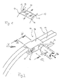
- FIG. 2 is an embodiment of the left front slider assembly 14 in FIG Detail shown.
- the guide element 12 is designed as a horizontally oriented web-like Guide formed, wherein the in-roof transverse direction end of the Web formed as a cylindrical circular guide 16 with a circular cross-section is.
- "Circular guide” should be understood here as a guide element, which in the gripped by a slider assembly part has an outer peripheral surface having rounded contours, i. the cross-sectional shape in this area is rounded off on the outer circumference, the cross-sectional shape is preferably circular.
- the round guide 16 is shown in FIGS. 3, 4 and 8 each of a front pivot 18 and a roof in the longitudinal direction rear offset to rear arranged rotary glider 20 embraced.
- the rotary gliders 18 and 20 are preferably made of plastic and are in corresponding Bearing 22 of a cage 24 for the rotary slider 18, 20 added.
- the rotary gliders 18, 20 each extend around a roof transverse direction Rotary shaft 36 rotatably mounted with respect to the bearing shells 22.
- the cage 24 is also inwardly extending in the roof transverse direction
- Rotary shaft 26 provided in a tubular receptacle 28, which coincides with the Dekkelelement 10 is connected, is plugged in that the rotary shaft 26 with respect the receptacle 28 displaceable in the roof transverse direction and the roof in the transverse direction extending longitudinal axis of the rotary shaft 26 rotatable with respect to the recording 28 is mounted in the receptacle 28 (these degrees of freedom are in Fig. 2 with Arrows indicated).
- the rotary shaft 26 is in the area of the front rotary glider 18 trained.
- the cage 24 is provided with a contact surface 30, which as Contact surface or stop for the front rotary glider 18 in the roof transverse direction serves inside. In the roof transverse direction to the outside of the front slider 18 is against with respect to the cage 24 free. Conversely, the cage 24 with a contact surface 32 provided, which as a stop for the rear rotary slider 20 in the roof transverse direction acting outwards while in the roof transverse direction inwards of the cage 24 is free.
- the round guide 16 is shown in FIGS. 2 and 8 are relatively strong in the roof longitudinal curved and roof raised plane spanned. As a result of that two rotary slides 18, 20 are provided, which with respect to the cage 24 respectively can be rotated about a rotational axis extending in the roof transverse direction 36, despite torsionally trained trained cage 24 a smooth guide along the guide member 12 can be achieved without excessive friction or a Tilting of the slider assembly 14 would occur.
- a rotation of the bearing cage 24 about an axis of rotation lying in the roof transverse direction 36 during the adjustment along the guide member 12 may with respect of the lid member 10 by the described pivot bearing of the rotary shaft 26 at the connection formed by the rotary shaft 26 and the receptacle 28 34 be balanced. This also applies to a deviation from a parallelism between the two guide elements 12.
- FIGS. 5 to 7 differs from the one described so far First embodiment essentially in that here the Slider assembly 114 additionally for curved in the roof transverse direction, i. in all three spatial directions curved guide elements 12 is suitable.
- the curvature of the guide element 112 is indicated in Fig. 5 with broken lines.
- the bearing shells 22 of the cage 124 on the open side closed by cover 138 the example, as indicated in Fig. 5 by means of a screw connection the cage 124 may be attached.
- the bearing surface formed by the cover 138 in roof transverse direction to the outside or inward is in Fig. 6 and Fig. 7th denoted by reference numerals 144 and 146, respectively.
- the rotary shaft 126 is not fixedly connected to the cage 124, but via a fork guide 140 to a running in the roof upwards direction Swivel bearing axle 142 pivotally connected to the cage 124 (this Degree of freedom is indicated in Fig. 5 with corresponding arrows). Furthermore, the Rotary shaft 126 in the embodiment of FIG. 2 rotatable and axially displaceable stored in the receptacle 128.
- connection arrangement 134 formed so that the cage 124 with respect to the lid member 10 displaceable in the roof transverse direction to a running in the roof upward direction Axis 142 pivotable and about an axis extending in the roof transverse direction axis 136 is rotatable.
Landscapes
- Engineering & Computer Science (AREA)
- Mechanical Engineering (AREA)
- Fittings On The Vehicle Exterior For Carrying Loads, And Devices For Holding Or Mounting Articles (AREA)
Abstract
Description
- FIG. 1
- eine schematische perspektivische Ansicht einer erfindungsgemäßen Führungsanordnung für ein Deckelelement eines Fahrzeugdaches;
- FIG. 2
- eine schematische vergrößerte perspektivische Detailansicht der Führungsanordnung gemäß einer ersten Ausführungsform;
- FIG. 3
- eine Schnittansicht entlang der Linie III-III in Fig. 2;
- FIG. 4
- eine Schnittansicht entlang der Linie IV-IV in Fig. 2;
- FIG. 5
- eine Ansicht wie Fig. 2, wobei jedoch eine alternative Ausführungsform der Führungsanordnung dargestellt ist;
- FIG. 6
- eine Schnittansicht entlang der Linie VI-VI von Fig. 5;
- FIG. 7
- eine Schnittansicht entlang der Linie VII-VII von Fig. 5; und
- FIG. 8
- eine Ansicht entsprechend Fig. 2, wobei jedoch die Darstellung aus der in Fig. 2 mit "X" bezeichneten Richtung erfolgt.
- 10
- Deckelelement
- 12, 112
- Führungselement
- 14, 114
- Gleiteranordnung
- 16
- Rundführung
- 18, 20
- Drehgleiter
- 22
- Lagerschalen
- 24, 124
- Käfig für 18, 20
- 26, 126
- Drehschaft
- 28, 128
- Aufnahme für 26, 126
- 30, 32
- Anlageflächen an 24, 124 für 18 bzw. 20
- 34, 134
- Verbindungsanordnung
- 36, 136
- Schwenkachse
- 138
- Deckel für 22
- 140
- Gabelführung
- 142
- Drehachse von 140
- 144, 146
- Anlageflächen von 138
Claims (12)
- Führungsanordnung für ein in Dachlängsrichtung verschiebbar geführtes Verschlusselement (10) für eine Dachöffnung eines Fahrzeugdaches, mit einem karosseriefesten, in Dachlängsrichtung verlaufenden Führungselement (12, 112) auf jeder Seite des Verschlusselements (10), welches jeweils von mindestens einer Gleiteranordnung (14, 114) umgriffen wird, die auf dem Führungselement (12, 112) verschiebbar gelagert ist und mit dem Verschlusselement (10) über eine Verbindungsanordnung (34, 134) verbunden ist,
dadurch gekennzeichnet, dass die Führungselemente (12, 112) jeweils eine Rundführung (16) aufweisen und jede Gleiteranordnung (14, 114) einen mit der Verbindungsanordnung (34, 134) verbundenen Drehgleiterkäfig (24, 124) und mindestens einen Drehgleiter (18, 20) umfasst, wobei der bzw. jeder Drehgleiter (18, 20) die Rundführung (16) umgreift und in dem Drehgleiterkäfig (24, 124) um eine in Dachquerrichtung verlaufende Drehachse (36, 136) drehbar gelagert ist. - Führungsanordnung gemäß Anspruch 1,
dadurch gekennzeichnet, dass der von dem bzw. den Drehgleiter(n) (18, 20) umgriffene Teil jeder Rundführung (16) eine kreisförmige Querschnittsform aufweist. - Führungsanordnung gemäß Anspruch 1 oder 2,
dadurch gekennzeichnet, dass jede Gleiteranordnung (14, 114) zwei in Dachlängsrichtung versetzte Drehgleiter (18, 20) umfasst. - Führungsanordnung gemäß Anspruch 1 bis 3,
dadurch gekennzeichnet, dass bei jeder Gleiteranordnung (14) der Käfig (24) für den einen Drehgleiter (20) eine Anlagefläche (32) nach außen in der Dachquerrichtung und für den anderen Drehgleiter (18) eine Anlagefläche (30) nach innen in der Dachquerrichtung umfasst, während die Drehgleiter (18, 20) in der jeweils anderen Richtung nach innen bzw. außen bezüglich des Käfigs (24) frei sind. - Führungsanordnung gemäß einem der Ansprüche 1 bis 3,
dadurch gekennzeichnet, dass bei jeder Gleiteranordnung (114) der Käfig (124) für beide Drehgleiter (18, 20) je eine Anlagefläche (30, 32, 144, 146) nach außen und nach innen in der Dachquerrichtung umfasst. - Führungsanordnung gemäß einem der Ansprüche 1 bis 5,
dadurch gekennzeichnet, dass die Verbindungsanordnung (34, 134) so ausgebildet ist, dass der Drehgleiterkäfig (24, 124) bezüglich des Verschlusselements (10) in Dachquerrichtung verschiebbar und um eine in Dachquerrichtung verlaufende Drehachse (36, 136) schwenkbar ist. - Führungsanordnung gemäß Anspruch 6,
dadurch gekennzeichnet, dass die Verbindungsanordnung (34, 134) so ausgebildet ist, dass der Drehgleiterkäfig (24, 124) bezüglich des Verschlusselements (10) zusätzlich um eine in Dachhochrichtung verlaufende Drehachse (142) schwenkbar ist. - Führungsanordnung gemäß Anspruch 6 oder 7,
dadurch gekennzeichnet, dass jeder Käfig (24, 124) mit einem nach innen in Dachquerrichtung abstehenden Drehschaft (26, 126) verbunden ist, der so mit einem mit dem Verschlusselement (10) verbundenen Gegenstück (28, 128) in Steckeingriff steht, dass er bezüglich des Gegenstücks (28, 128) in Dachquerrichtung verschiebbar und um die Schaftachse (36, 136) drehbar ist. - Führungsanordnung gemäß Anspruch 8,
dadurch gekennzeichnet, dass das Gegenstück als Aufnahme (28, 128) ausgebildet ist, in welche der Drehschaft (26, 126) eingesteckt ist. - Führungsanordnung gemäß Anspruch 8 oder 9, sofern auf Anspruch 6 zurückbezogen,
dadurch gekennzeichnet, dass jeder Drehschaft (26) fest mit dem entsprechenden Käfig (24) verbunden ist. - Führungsanordnung gemäß Anspruch 8 oder 9, sofern auf Anspruch 6 zurückbezogen,
dadurch gekennzeichnet, dass jeder Drehschaft (126) über ein Drehlager (142), dessen Schwenkachse in Dachhochrichtung verläuft, mit dem entsprechenden Käfig (124) verbunden ist. - Führungsanordnung gemäß einem der Ansprüche1 bis 11,
dadurch gekennzeichnet, dass an jeder Seite des Verschlusselements (10) zwei in Dachlängsrichtung versetzte Gleiteranordnungen (14, 114) vorgesehen sind.
Applications Claiming Priority (2)
| Application Number | Priority Date | Filing Date | Title |
|---|---|---|---|
| DE10137949 | 2001-08-07 | ||
| DE2001137949 DE10137949C2 (de) | 2001-08-07 | 2001-08-07 | Führungsanordnung für ein öffnungsfähiges Fahrzeugdach |
Publications (2)
| Publication Number | Publication Date |
|---|---|
| EP1285796A1 true EP1285796A1 (de) | 2003-02-26 |
| EP1285796B1 EP1285796B1 (de) | 2006-11-08 |
Family
ID=7694161
Family Applications (1)
| Application Number | Title | Priority Date | Filing Date |
|---|---|---|---|
| EP20020016701 Expired - Lifetime EP1285796B1 (de) | 2001-08-07 | 2002-07-26 | Führungsanordnung für ein öffnungsfähiges Fahrzeugdach |
Country Status (2)
| Country | Link |
|---|---|
| EP (1) | EP1285796B1 (de) |
| DE (2) | DE10137949C2 (de) |
Cited By (4)
| Publication number | Priority date | Publication date | Assignee | Title |
|---|---|---|---|---|
| EP1754659A3 (de) * | 2005-08-16 | 2007-06-13 | Besenzoni S.p.A. | Schiebevorrichtung, insbesondere für ausnehmbare Bootsverdeck |
| DE102008017526B3 (de) * | 2008-04-03 | 2009-09-17 | Webasto Ag | Gleitereinheit eines bewegbaren Deckels eines öffnungsfähigen Fahrzeugdaches |
| US9065423B2 (en) | 2008-09-27 | 2015-06-23 | Witricity Corporation | Wireless energy distribution system |
| WO2016092039A1 (de) | 2014-12-12 | 2016-06-16 | Webasto SE | Fahrzeug mit einem gleiter zum führen eines verlagerbaren elements |
Citations (5)
| Publication number | Priority date | Publication date | Assignee | Title |
|---|---|---|---|---|
| GB2164006A (en) * | 1984-09-06 | 1986-03-12 | Autoroofs Ltd | Vehicle sunroofs |
| US4892351A (en) * | 1987-03-13 | 1990-01-09 | Honda Giken Kogyo K.K. | Water drain trough for automotive sunroof |
| US5114208A (en) * | 1989-08-04 | 1992-05-19 | Aisin Seiki Kabushiki Kaisha | Sliding mechanism for sunroof |
| DE19514586A1 (de) * | 1995-04-20 | 1996-10-24 | Gubesch Gmbh | Lagerbock für das Kulissenelement eines Fahrzeug-Schiebe-Hebedaches |
| DE10024442C1 (de) * | 2000-05-19 | 2001-08-02 | Webasto Vehicle Sys Int Gmbh | Öffnungsfähiges Fahrzeugdach |
Family Cites Families (3)
| Publication number | Priority date | Publication date | Assignee | Title |
|---|---|---|---|---|
| US3005226A (en) * | 1958-10-29 | 1961-10-24 | Golde Gmbh H T | Guide shoes for guiding movable roofs along guide rails |
| DE2313453B2 (de) * | 1973-03-17 | 1976-02-05 | Webasto-Werk W. Baier Kg, 8031 Stockdorf | Hoehenverstellvorrichtung an schiebedaechern |
| DE19514585C5 (de) * | 1995-04-20 | 2004-11-18 | Gubesch Gmbh | Schiebeelement für ein Kulissenteil eines Schiebe/Hebedaches eines Kraftfahrzeugs |
-
2001
- 2001-08-07 DE DE2001137949 patent/DE10137949C2/de not_active Expired - Fee Related
-
2002
- 2002-07-26 EP EP20020016701 patent/EP1285796B1/de not_active Expired - Lifetime
- 2002-07-26 DE DE50208641T patent/DE50208641D1/de not_active Expired - Lifetime
Patent Citations (5)
| Publication number | Priority date | Publication date | Assignee | Title |
|---|---|---|---|---|
| GB2164006A (en) * | 1984-09-06 | 1986-03-12 | Autoroofs Ltd | Vehicle sunroofs |
| US4892351A (en) * | 1987-03-13 | 1990-01-09 | Honda Giken Kogyo K.K. | Water drain trough for automotive sunroof |
| US5114208A (en) * | 1989-08-04 | 1992-05-19 | Aisin Seiki Kabushiki Kaisha | Sliding mechanism for sunroof |
| DE19514586A1 (de) * | 1995-04-20 | 1996-10-24 | Gubesch Gmbh | Lagerbock für das Kulissenelement eines Fahrzeug-Schiebe-Hebedaches |
| DE10024442C1 (de) * | 2000-05-19 | 2001-08-02 | Webasto Vehicle Sys Int Gmbh | Öffnungsfähiges Fahrzeugdach |
Cited By (5)
| Publication number | Priority date | Publication date | Assignee | Title |
|---|---|---|---|---|
| EP1754659A3 (de) * | 2005-08-16 | 2007-06-13 | Besenzoni S.p.A. | Schiebevorrichtung, insbesondere für ausnehmbare Bootsverdeck |
| DE102008017526B3 (de) * | 2008-04-03 | 2009-09-17 | Webasto Ag | Gleitereinheit eines bewegbaren Deckels eines öffnungsfähigen Fahrzeugdaches |
| US9065423B2 (en) | 2008-09-27 | 2015-06-23 | Witricity Corporation | Wireless energy distribution system |
| WO2016092039A1 (de) | 2014-12-12 | 2016-06-16 | Webasto SE | Fahrzeug mit einem gleiter zum führen eines verlagerbaren elements |
| DE102014018285A1 (de) | 2014-12-12 | 2016-06-16 | Webasto SE | Fahrzeug mit einem Gleiter zum Führen eines verlagerbaren Elements |
Also Published As
| Publication number | Publication date |
|---|---|
| EP1285796B1 (de) | 2006-11-08 |
| DE10137949A1 (de) | 2003-03-06 |
| DE10137949C2 (de) | 2003-06-18 |
| DE50208641D1 (de) | 2006-12-21 |
Similar Documents
| Publication | Publication Date | Title |
|---|---|---|
| DE102005048786A1 (de) | Türe, insbesondere für ein Kraftfahrzeug | |
| EP1112876A2 (de) | Sonnenschutzvorrichtung für einen lichtdurchlässigen Fahrzeugdachbereich | |
| DE102010034566A1 (de) | Ausstellvorrichtung für ein öffnungsfähiges Fahrzeugdach und öffnungsfähiges Fahrzeugdach | |
| EP1506103A1 (de) | Abdeckvorrichtung für einen verdeckkasten eines cabriolet-fahrzeugs | |
| DE3532318C1 (de) | Schiebedach fuer Kraftfahrzeuge | |
| EP0221241A2 (de) | Schiebedach für ein Kraftfahrzeug, insbesondere Personenkraftwagen | |
| EP0058294A1 (de) | Anordnung einer Sonnenblende oberhalb einer Seitenscheibe in einem Fahrzeug | |
| EP1254799A2 (de) | Öffnungsfähiges Fahrzeugdach | |
| DE10002457C2 (de) | Schiebedach | |
| DE10143823A1 (de) | Fahrzeugdach | |
| EP1285796B1 (de) | Führungsanordnung für ein öffnungsfähiges Fahrzeugdach | |
| DE19745756C2 (de) | Abdeckleiste | |
| EP1254800B1 (de) | Dachanordnung für ein Fahrzeug | |
| DE19959542C2 (de) | Vorrichtung zum Verstellen eines Kulissenelements eines öffnungsfähigen Fahrzeugdaches | |
| EP1179443B1 (de) | Windschott | |
| DE19714106C2 (de) | Umwandelbares Fahrzeugdach | |
| DE60225950T2 (de) | Schiebetüren mit Betätigungsmechanismus | |
| DE10110014B4 (de) | Antriebsanordnung für ein zur Ablage in einen Stauraum in einem Fahrzeug schwenkbares Element eines Fahrzeugdaches | |
| DE102004055404A1 (de) | Fahrzeugdach | |
| DE69925217T2 (de) | Konstruktion eines öffnungsfähigen Fahrzeugdaches | |
| DE10333474A1 (de) | Vorrichtung zur Ausstattung des Daches eines Kraftfahrzeuges mit einem Rollo und einem Schiebedeckel, die von dem gleichen Motor angetrieben werden | |
| DE602004010568T2 (de) | Versenkbares Dach für ein Kraftfahrzeug | |
| DE102015007679A1 (de) | Verriegelungseinrichtung für ein Flügelelement eines Kraftwagens | |
| EP1647429B1 (de) | Dachanordnung für ein Fahrzeug | |
| DE3404124C2 (de) |
Legal Events
| Date | Code | Title | Description |
|---|---|---|---|
| PUAI | Public reference made under article 153(3) epc to a published international application that has entered the european phase |
Free format text: ORIGINAL CODE: 0009012 |
|
| AK | Designated contracting states |
Kind code of ref document: A1 Designated state(s): AT BE BG CH CY CZ DE DK EE ES FI FR GB GR IE IT LI LU MC NL PT SE SK TR |
|
| AX | Request for extension of the european patent |
Extension state: AL LT LV MK RO SI |
|
| 17P | Request for examination filed |
Effective date: 20030729 |
|
| AKX | Designation fees paid |
Designated state(s): DE FR GB NL |
|
| GRAP | Despatch of communication of intention to grant a patent |
Free format text: ORIGINAL CODE: EPIDOSNIGR1 |
|
| GRAS | Grant fee paid |
Free format text: ORIGINAL CODE: EPIDOSNIGR3 |
|
| GRAA | (expected) grant |
Free format text: ORIGINAL CODE: 0009210 |
|
| AK | Designated contracting states |
Kind code of ref document: B1 Designated state(s): DE FR GB NL |
|
| REG | Reference to a national code |
Ref country code: GB Ref legal event code: FG4D Free format text: NOT ENGLISH |
|
| REF | Corresponds to: |
Ref document number: 50208641 Country of ref document: DE Date of ref document: 20061221 Kind code of ref document: P |
|
| GBT | Gb: translation of ep patent filed (gb section 77(6)(a)/1977) |
Effective date: 20070213 |
|
| ET | Fr: translation filed | ||
| PLBE | No opposition filed within time limit |
Free format text: ORIGINAL CODE: 0009261 |
|
| STAA | Information on the status of an ep patent application or granted ep patent |
Free format text: STATUS: NO OPPOSITION FILED WITHIN TIME LIMIT |
|
| 26N | No opposition filed |
Effective date: 20070809 |
|
| REG | Reference to a national code |
Ref country code: FR Ref legal event code: TP |
|
| REG | Reference to a national code |
Ref country code: FR Ref legal event code: PLFP Year of fee payment: 15 |
|
| REG | Reference to a national code |
Ref country code: FR Ref legal event code: PLFP Year of fee payment: 16 |
|
| REG | Reference to a national code |
Ref country code: FR Ref legal event code: PLFP Year of fee payment: 17 |
|
| PGFP | Annual fee paid to national office [announced via postgrant information from national office to epo] |
Ref country code: NL Payment date: 20190722 Year of fee payment: 18 |
|
| PGFP | Annual fee paid to national office [announced via postgrant information from national office to epo] |
Ref country code: DE Payment date: 20190723 Year of fee payment: 18 Ref country code: FR Payment date: 20190724 Year of fee payment: 18 |
|
| PGFP | Annual fee paid to national office [announced via postgrant information from national office to epo] |
Ref country code: GB Payment date: 20190725 Year of fee payment: 18 |
|
| REG | Reference to a national code |
Ref country code: DE Ref legal event code: R119 Ref document number: 50208641 Country of ref document: DE |
|
| REG | Reference to a national code |
Ref country code: NL Ref legal event code: MM Effective date: 20200801 |
|
| GBPC | Gb: european patent ceased through non-payment of renewal fee |
Effective date: 20200726 |
|
| PG25 | Lapsed in a contracting state [announced via postgrant information from national office to epo] |
Ref country code: GB Free format text: LAPSE BECAUSE OF NON-PAYMENT OF DUE FEES Effective date: 20200726 Ref country code: FR Free format text: LAPSE BECAUSE OF NON-PAYMENT OF DUE FEES Effective date: 20200731 Ref country code: NL Free format text: LAPSE BECAUSE OF NON-PAYMENT OF DUE FEES Effective date: 20200801 |
|
| PG25 | Lapsed in a contracting state [announced via postgrant information from national office to epo] |
Ref country code: DE Free format text: LAPSE BECAUSE OF NON-PAYMENT OF DUE FEES Effective date: 20210202 |