EP1288762A2 - Bedienungselement für eine Antriebsvorrichtung - Google Patents
Bedienungselement für eine Antriebsvorrichtung Download PDFInfo
- Publication number
- EP1288762A2 EP1288762A2 EP02015390A EP02015390A EP1288762A2 EP 1288762 A2 EP1288762 A2 EP 1288762A2 EP 02015390 A EP02015390 A EP 02015390A EP 02015390 A EP02015390 A EP 02015390A EP 1288762 A2 EP1288762 A2 EP 1288762A2
- Authority
- EP
- European Patent Office
- Prior art keywords
- operating position
- predetermined operating
- drive device
- drive power
- predetermined
- Prior art date
- Legal status (The legal status is an assumption and is not a legal conclusion. Google has not performed a legal analysis and makes no representation as to the accuracy of the status listed.)
- Granted
Links
- 238000001514 detection method Methods 0.000 claims 1
- 208000003443 Unconsciousness Diseases 0.000 description 1
- 238000000418 atomic force spectrum Methods 0.000 description 1
- 239000012528 membrane Substances 0.000 description 1
- 230000003287 optical effect Effects 0.000 description 1
- 230000000630 rising effect Effects 0.000 description 1
- 230000000007 visual effect Effects 0.000 description 1
Images


Classifications
-
- A—HUMAN NECESSITIES
- A61—MEDICAL OR VETERINARY SCIENCE; HYGIENE
- A61G—TRANSPORT, PERSONAL CONVEYANCES, OR ACCOMMODATION SPECIALLY ADAPTED FOR PATIENTS OR DISABLED PERSONS; OPERATING TABLES OR CHAIRS; CHAIRS FOR DENTISTRY; FUNERAL DEVICES
- A61G5/00—Chairs or personal conveyances specially adapted for patients or disabled persons, e.g. wheelchairs
- A61G5/04—Chairs or personal conveyances specially adapted for patients or disabled persons, e.g. wheelchairs motor-driven
- A61G5/047—Chairs or personal conveyances specially adapted for patients or disabled persons, e.g. wheelchairs motor-driven by a modular detachable drive system
-
- A—HUMAN NECESSITIES
- A61—MEDICAL OR VETERINARY SCIENCE; HYGIENE
- A61G—TRANSPORT, PERSONAL CONVEYANCES, OR ACCOMMODATION SPECIALLY ADAPTED FOR PATIENTS OR DISABLED PERSONS; OPERATING TABLES OR CHAIRS; CHAIRS FOR DENTISTRY; FUNERAL DEVICES
- A61G5/00—Chairs or personal conveyances specially adapted for patients or disabled persons, e.g. wheelchairs
- A61G5/04—Chairs or personal conveyances specially adapted for patients or disabled persons, e.g. wheelchairs motor-driven
- A61G5/048—Power-assistance activated by pushing on hand rim or on handlebar
-
- A—HUMAN NECESSITIES
- A61—MEDICAL OR VETERINARY SCIENCE; HYGIENE
- A61G—TRANSPORT, PERSONAL CONVEYANCES, OR ACCOMMODATION SPECIALLY ADAPTED FOR PATIENTS OR DISABLED PERSONS; OPERATING TABLES OR CHAIRS; CHAIRS FOR DENTISTRY; FUNERAL DEVICES
- A61G5/00—Chairs or personal conveyances specially adapted for patients or disabled persons, e.g. wheelchairs
- A61G5/10—Parts, details or accessories
- A61G5/1051—Arrangements for steering
-
- B—PERFORMING OPERATIONS; TRANSPORTING
- B60—VEHICLES IN GENERAL
- B60L—PROPULSION OF ELECTRICALLY-PROPELLED VEHICLES; SUPPLYING ELECTRIC POWER FOR AUXILIARY EQUIPMENT OF ELECTRICALLY-PROPELLED VEHICLES; ELECTRODYNAMIC BRAKE SYSTEMS FOR VEHICLES IN GENERAL; MAGNETIC SUSPENSION OR LEVITATION FOR VEHICLES; MONITORING OPERATING VARIABLES OF ELECTRICALLY-PROPELLED VEHICLES; ELECTRIC SAFETY DEVICES FOR ELECTRICALLY-PROPELLED VEHICLES
- B60L15/00—Methods, circuits, or devices for controlling the traction-motor speed of electrically-propelled vehicles
- B60L15/20—Methods, circuits, or devices for controlling the traction-motor speed of electrically-propelled vehicles for control of the vehicle or its driving motor to achieve a desired performance, e.g. speed, torque, programmed variation of speed
-
- G—PHYSICS
- G05—CONTROLLING; REGULATING
- G05G—CONTROL DEVICES OR SYSTEMS INSOFAR AS CHARACTERISED BY MECHANICAL FEATURES ONLY
- G05G1/00—Controlling members, e.g. knobs or handles; Assemblies or arrangements thereof; Indicating position of controlling members
- G05G1/02—Controlling members for hand actuation by linear movement, e.g. push buttons
-
- G—PHYSICS
- G05—CONTROLLING; REGULATING
- G05G—CONTROL DEVICES OR SYSTEMS INSOFAR AS CHARACTERISED BY MECHANICAL FEATURES ONLY
- G05G5/00—Means for preventing, limiting or returning the movements of parts of a control mechanism, e.g. locking controlling member
- G05G5/03—Means for enhancing the operator's awareness of arrival of the controlling member at a command or datum position; Providing feel, e.g. means for creating a counterforce
-
- A—HUMAN NECESSITIES
- A61—MEDICAL OR VETERINARY SCIENCE; HYGIENE
- A61G—TRANSPORT, PERSONAL CONVEYANCES, OR ACCOMMODATION SPECIALLY ADAPTED FOR PATIENTS OR DISABLED PERSONS; OPERATING TABLES OR CHAIRS; CHAIRS FOR DENTISTRY; FUNERAL DEVICES
- A61G2203/00—General characteristics of devices
- A61G2203/10—General characteristics of devices characterised by specific control means, e.g. for adjustment or steering
- A61G2203/14—Joysticks
-
- Y—GENERAL TAGGING OF NEW TECHNOLOGICAL DEVELOPMENTS; GENERAL TAGGING OF CROSS-SECTIONAL TECHNOLOGIES SPANNING OVER SEVERAL SECTIONS OF THE IPC; TECHNICAL SUBJECTS COVERED BY FORMER USPC CROSS-REFERENCE ART COLLECTIONS [XRACs] AND DIGESTS
- Y02—TECHNOLOGIES OR APPLICATIONS FOR MITIGATION OR ADAPTATION AGAINST CLIMATE CHANGE
- Y02T—CLIMATE CHANGE MITIGATION TECHNOLOGIES RELATED TO TRANSPORTATION
- Y02T10/00—Road transport of goods or passengers
- Y02T10/60—Other road transportation technologies with climate change mitigation effect
- Y02T10/64—Electric machine technologies in electromobility
-
- Y—GENERAL TAGGING OF NEW TECHNOLOGICAL DEVELOPMENTS; GENERAL TAGGING OF CROSS-SECTIONAL TECHNOLOGIES SPANNING OVER SEVERAL SECTIONS OF THE IPC; TECHNICAL SUBJECTS COVERED BY FORMER USPC CROSS-REFERENCE ART COLLECTIONS [XRACs] AND DIGESTS
- Y02—TECHNOLOGIES OR APPLICATIONS FOR MITIGATION OR ADAPTATION AGAINST CLIMATE CHANGE
- Y02T—CLIMATE CHANGE MITIGATION TECHNOLOGIES RELATED TO TRANSPORTATION
- Y02T10/00—Road transport of goods or passengers
- Y02T10/60—Other road transportation technologies with climate change mitigation effect
- Y02T10/72—Electric energy management in electromobility
Definitions
- the invention relates to an operating element for a Drive device for driving a means of transport, in particular an electrically driven wheelchair.
- Wheelchairs are often needed by the elderly. Their Life companions who mostly push the wheelchair have also often reached an advanced age and sometimes get fast when pushing wheelchairs to their performance limit. For the elderly, the one Push wheelchair, therefore, provide gradients and gradients often insurmountable obstacles.
- This known sliding aid has an operating element a control element having a Betsch Trentsweg with having two predetermined operating positions, wherein at a first predetermined operating position the Drive power of the drive device is zero, the Drive power of the drive device upon actuation of the Control element in a first direction starting from this first predetermined operating position increases and the Drive power of the drive device when reaching a second predetermined operating position a maximum value reached.
- a pushing aid for a wheelchair executed known drive device has a Operating element with an operating lever, which is located in not actuated state is in a zero position. In This zero position is the driving power of Drive device equal to zero. Will the operating lever pressed against a spring force, the rising Drive power with increasing actuation path. If the full actuation path is utilized, i. of the Actuator lever has reached a stop, the maximum drive power provided.
- the invention is based on the object, the above explained technical problem to be solved.
- the solution of this The task is specified in claim 1.
- an operating element for a Drive device of the type described above characterized characterized in that the actuating travel of Control in the first direction over the second extends predetermined operating position addition, wherein the Exceeding the second predetermined operating position in the first direction exceeds a predetermined one Operating force is required and wherein the crossing the second predetermined operating position in the first Direction has the consequence that the drive power of Drive device is changed.
- control element according to the invention has a such adherence to the result that the drive power not maintained at their current value, but is changed.
- the change may be according to the embodiment of the invention or depending on the operation of a corresponding one Be different switching element.
- the change can for example, that the drive power, if necessary successively, withdrawn in amount is, immediately goes back to zero or changed or constant drive power only a reversal the drive direction takes place.
- the actuating force increases along the Actuating path of the control element in the first Direction from the first predetermined operating position until to reach the second predetermined operating position.
- the for reaching the second predetermined operating position predetermined actuating force is preferably less than that for exceeding the second predetermined Operating position required in the first direction Operating force.
- the function of the Operating force on the actuation of the Control element in the first direction in the area of second predetermined operating position preferably discontinuous, wherein the actuating force after reaching the second predetermined operating position initially discontinuous rises and after exceeding the second predetermined Operating position in the first direction drops.
- this is Control element pivotally mounted and as a control lever executed so that this by hand force against a Spring force from the first predetermined operating position in the second predetermined operating position can be brought.
- This is preferably by the deformation of the elastically deformable element Contact closed with the result that the drive power the drive device is changed.
- the deformable element is preferably a so-called Snap spring with tactile feedback. Characteristic of such a snap spring is the non-linear characteristic the operating force, the clear snapping after Reaching the operating force and the automatic Provision. It is a so-called Monostable spring element, as used in other things Finds membrane keyboards.
- control element is preferably a potentiometer for controlling the drive power of Drive device actuated.
- the Exceeding the second predetermined operating position in the first direction resulting values of the potentiometer recognize as shutdown and designed to be the Drive device when detecting these cut-off values so to control that the drive power of Drive device is changed.
- the invention also relates to a sliding and / or Brake aid for a wheelchair with a control element the type explained above.
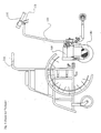
- Fig. 5 shows in three successive representations one Case in which a person in a wheelchair 200 a slope with the help of an assistant. Leads to this the assistant a sliding / braking aid 100 from the back the wheelchair 200 approached, the former attached to the latter and can then with the support of the sliding / braking aid 100 master the slope.
- Fig. 6 shows schematically a wheelchair 200, wherein from For the sake of illustration omitted a part of the rear wheels is, as well as a sliding / braking aid 100.
- the sliding / braking aid 100 which, as shown in Fig. 5, on the Wheelchair 200 is attachable, has a separate Handle 110 with an actuating lever 111. It understands Go for the expert that other configurations possible are both with respect to the arrangement of the handle 110 as also with respect to the actuating lever 111.
- the handle 110 directly to a handle end 210th of the wheelchair 200 are postponed.
- This can be a Handrail 120 omitted on the push bar and by a Transfer means between the handle 110 and the Push aid 100, for example, a cable (not shown).
- Fig. 7 shows a rear view of the wheelchair 200 with assembled sliding / braking aid 100.
- the drive wheel 140 of the sliding / braking aid 100 slightly raised and can be lowered as needed be that it has sufficient ground contact and in this Position exercise its function as a sliding / braking aid 100 can.
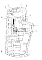
- Fig. 1 shows a sectional view of a first Embodiment of an operating element according to the invention.
- the control element can optionally be on the left or right push handle 210 of a wheelchair can be attached, preferably via a corresponding inlet 301 in FIG the open end of the wheelchair handle 210 is inserted and over a ball seat and a thumbscrew is fixed. It is understood by those skilled in the art that any further Mounting possibilities of the operating element on the Wheelchair are possible.
- a Main control board 303 In a front part 302 of the housing is a Main control board 303 arranged. A transmitter board 304 with a slide potentiometer 304 A is in the handle parts 305th and 306 arranged. At the lower handle portion 306 is a as Control lever designed control element 320 pivotally stored. The control lever 320 is located above a U-shaped recess 321 with the slide potentiometer 304 A. engaged.
- the control lever 320 is moved by a spring 322 in the direction pressed a first operating position.
- this first Operating position is the sliding potentiometer 304 A in a position in which the power of the Drive device is zero.
- Stop element 323 of the control lever 320 After a predetermined actuation path arrives Stop element 323 of the control lever 320 with an on the encoder board 304 arranged elastically deformable Element 340 in contact.
- this second predetermined Operating position of the actuating lever 320 is the Slide potentiometer 304 A in a position in which the maximum drive power of the drive device provided.
- the touch of the stop element 323 with the elastic deformable element 340 provides for the operator noticeable stop.
- the elasticity of the elastic deformable element 340 is chosen such that a Exceeding the actuation path in the first direction of the starting position, i. the first predetermined Operating position, in which the performance of the drive device is equal to zero, in the second predetermined operating position, in which the maximum drive power is present, at normal Operation is not exceeded. Will one, however noticeably increased force applied, this deforms elastically deformable element such that the Operating lever further in the first defined above Direction can be actuated. This is at the Encoder board 304 closed a contact, which causes the drive power of the drive device is changed.
- the elastically deformable element 340 is a snap spring or snap-action disc, as for example of the company INOVAN-Stroebe KG, 75217 Birkenfeld, Germany, commercially available.
- a snap spring has a curvature whose convex side at rest the Stop element 323 of the control lever 320 faces.
- the Stop member 323 When exceeding the second predetermined operating position in the direction of the first actuating travel expresses the Stop member 323, the said curvature, wherein a Snapping takes place, so that the stop element 323 of the Control lever 320 now with the concave side of Vault is in contact. In this position that concludes elastically deformable element 340 makes contact on the Encoder board 304.
- This closing of the contact on the encoder board 304 causes a change in the drive power of Drive device.
- This can be changed in amount are, i. for example, immediately to zero be withdrawn or reduced in amount. It However, it is also possible to drive power in their Reversing direction, in which case the drive power the Amount after can also be reduced.
- the operating element a number of other operating features and functions may have, in particular a switch for switching on / off the sliding / braking aid, one Direction switch with which the direction of travel is selected can be, a thumbwheel with which a maximum possible Speed in the event that the control lever 320 is in the second predetermined operating position, can be chosen, this maximum speed for example, between 1.1 and 5.5 km / h, as well as Means for visual and / or audible indication of certain operating conditions, in particular the Possibility exists by means of an acoustic signal too little capacity of the accumulators do.
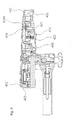
- Fig. 4 shows a second embodiment of the Control element according to the invention, which is essentially the in the figures 1 to 3 illustrated embodiment equivalent. Corresponding components are therefore with the the same reference numerals, which only by the number 100 were raised.
- the embodiment according to FIG. 4 differs from FIG essentially according to FIGS. 1 to 3, that the elastically deformable element 440 not on the Encoder board 404 is arranged and that there is no independent switching function takes over. That elastic deformable element 440 serves this second embodiment only to the second predetermined operating position of the To provide control lever 420, and allows, at Exceeding a predetermined operating force the Control lever 420 in the first direction of actuation this second predetermined operating position addition actuate. For this purpose, this is elastically deformable Element 440 also executed in the form of a snap spring.
- the control function will be on this second Embodiment of the sliding potentiometer 404 A which is designed to recognize that the exceeded second predetermined operating position, so that the electronic control at appropriate Potentiometer values a corresponding change in the Drive power of the drive device can cause. It is thus also a tactile behavior of the Operating element provided in which by means of Control lever, starting from a first Operating position in which the drive power of Drive device is zero, the drive power of the Drive device can be increased up to a Maximum value, which is at a second predetermined Operating position of the control lever 420 is present, wherein at further increased operating force exceeding this second predetermined operating position in the first Movement direction is possible, which then change the Drive power has the consequence.
- FIG. 1 differs from the one shown in FIG Representation of FIG. 4 also in that in Fig. 1 the first predetermined operating position is shown, i. the Zeroing, in which the drive power of Drive device is zero, while in Fig. 4 of the Control lever 420 in the second predetermined Operating position is shown at which the maximum Drive power of the drive device is present.
Landscapes
- Engineering & Computer Science (AREA)
- Public Health (AREA)
- General Health & Medical Sciences (AREA)
- Health & Medical Sciences (AREA)
- Veterinary Medicine (AREA)
- Life Sciences & Earth Sciences (AREA)
- Animal Behavior & Ethology (AREA)
- Automation & Control Theory (AREA)
- Physics & Mathematics (AREA)
- General Physics & Mathematics (AREA)
- Power Engineering (AREA)
- Transportation (AREA)
- Mechanical Engineering (AREA)
- Electric Propulsion And Braking For Vehicles (AREA)
- Mechanical Control Devices (AREA)
- Electronic Switches (AREA)
- Surgical Instruments (AREA)
- Portable Nailing Machines And Staplers (AREA)
Abstract
Description
Claims (10)
- Bedienungselement für eine Antriebsvorrichtung zum Antreiben eines Beförderungsmittels, insbesondere eines elektrisch antreibbaren Rollstuhl,
mit einem Steuerungselement, das einen Betätigungsweg mit mindestens zwei vorbestimmten Betriebsstellungen aufweist, wobei bei einer ersten vorbestimmten Betriebsstellung die Antriebsleistung der Antriebsvorrichtung gleich Null ist, die Antriebsleistung der Antriebsvorrichtung bei Betätigung des Steuerungselements in einer ersten Richtung (X) ausgehend von dieser ersten vorbestimmten Betriebsstellung ansteigt und die Antriebsleistung der Antriebsvorrichtung bei Erreichen einer zweiten vorbestimmten Betriebsstellung einen Maximalwert erreicht,
dadurch gekennzeichnet, dass sich der Betätigungsweg des Steuerungselements in der ersten Richtung (X) über die zweite vorbestimmte Betriebsstellung hinaus erstreckt, wobei zum Überschreiten der zweiten vorbestimmten Betriebsstellung in der ersten Richtung (X) ein Übersteigen einer vorbestimmten Betätigungskraft erforderlich ist und wobei das Überschreiten der zweiten vorbestimmten Betriebsstellung in der ersten Richtung (X) zur Folge hat, dass die Antriebsleistung der Antriebsvorrichtung verändert wird. - Bedienungselement nach Anspruch 1, dadurch gekennzeichnet, dass die Betätigungskraft längs des Betätigungsweges des Steuerungselements in der ersten Richtung (X) von der ersten vorbestimmten Betriebsstellung bis zum Erreichen der zweiten vorbestimmten Betriebsstellung ansteigt.
- Bedienungselement nach Anspruch 1 oder 2, dadurch gekennzeichnet, dass die zum Erreichen der zweiten vorbestimmten Betriebsstellung vorbestimmte Betätigungskraft kleiner ist als die zum Überschreiten der zweiten vorbestimmten Betriebsstellung in der ersten Richtung (X) erforderliche Betätigungskraft.
- Bedienungselement nach Anspruch 2 oder 3, dadurch gekennzeichnet, dass die Funktion der Betätigungskraft über dem Betätigungsweg des Steuerungselements in der ersten Richtung (X) im Bereich der zweiten vorbestimmten Betriebsstellung unstetig verläuft, wobei die Betätigungskraft nach dem Erreichen der zweiten vorbestimmten Betriebsstellung zunächst diskontinuierlich ansteigt und nach dem Überschreiten der zweiten vorbestimmten Betriebsstellung in der ersten Richtung (X) abfällt.
- Bedienungselement nach einem der vorstehenden Ansprüche, dadurch gekennzeichnet, dass das Steuerungselement schwenkbar gelagert und als Steuerungshebel so ausgeführt ist, dass er mittels Handkraft gegen eine Federkraft von der ersten vorbestimmten Betriebsstellung in die zweite vorbestimmte Betriebsstellung bringbar ist.
- Bedienungselement nach Anspruch 5, dadurch gekennzeichnet, dass in der zweiten vorbestimmten Betriebsstellung ein mechanischer Anschlag in Form eines elastisch verformbaren Elements bereitgestellt ist, das eine Wölbung aufweist, wobei ein mit dem Hebel verbundenes Bauteil beim Erreichen der zweiten vorbestimmten Betriebsstellung in der ersten Richtung (X) des Betätigungsweges mit der konvexen Seite der Wölbung in Berührung gelangt und bei Erhöhung der Betätigungskraft das elastisch verformbare Element im Bereich der Wölbung so verformt wird, dass die Berührungsstelle des mit dem Hebel verbundenen Bauteils im konkaven Teil der Wölbung liegt.
- Bedienungselement nach Anspruch 6, dadurch gekennzeichnet, dass durch die Verformung des elastisch verformbaren Elements ein Kontakt geschlossen wird mit der Folge, dass die Antriebsleistung der Antriebsvorrichtung verändert wird.
- Bedienungselement nach Anspruch 6, dadurch gekennzeichnet, dass durch Betätigung des Steuerungselements ein Potentiometer zur Steuerung der Antriebsleistung der Antriebsvorrichtung betätigt wird, wobei eine Steuerungseinrichtung die beim Überschreiten der zweiten vorbestimmten Betriebsstellung in der ersten Richtung (X) sich ergebenden Werte des Potentiometers als Abschaltwerte erkennt und dazu ausgelegt ist, die Antriebsvorrichtung bei Erkennung dieser Abschaltwerte so anzusteuern, dass die Antriebsleistung der Antriebsvorrichtung verändert wird.
- Bedienungselement nach einem der vorstehenden Ansprüche, dadurch gekennzeichnet, dass die Veränderung der Antriebsleistung beim Überschreiten der zweiten vorbestimmten Betriebsstellung in der ersten Richtung (X) darin besteht, dass die Antriebsleistung auf Null zurück geht.
- Schiebehilfe- und/oder Bremshilfe für einen Rollstuhl mit einem Bedienungselement nach einem der vorstehenden Ansprüche 1 bis 9.
Priority Applications (1)
| Application Number | Priority Date | Filing Date | Title |
|---|---|---|---|
| DE20221073U DE20221073U1 (de) | 2001-08-24 | 2002-07-11 | Schiebehilfe für einen Rollstuhl |
Applications Claiming Priority (2)
| Application Number | Priority Date | Filing Date | Title |
|---|---|---|---|
| DE10141566A DE10141566C1 (de) | 2001-08-24 | 2001-08-24 | Bedienungselement für eine Antriebsvorrichtung |
| DE10141566 | 2001-08-24 |
Publications (3)
| Publication Number | Publication Date |
|---|---|
| EP1288762A2 true EP1288762A2 (de) | 2003-03-05 |
| EP1288762A3 EP1288762A3 (de) | 2006-04-05 |
| EP1288762B1 EP1288762B1 (de) | 2010-03-03 |
Family
ID=7696512
Family Applications (1)
| Application Number | Title | Priority Date | Filing Date |
|---|---|---|---|
| EP02015390A Expired - Lifetime EP1288762B1 (de) | 2001-08-24 | 2002-07-11 | Bedienungselement für eine Antriebsvorrichtung |
Country Status (3)
| Country | Link |
|---|---|
| EP (1) | EP1288762B1 (de) |
| AT (1) | ATE459907T1 (de) |
| DE (2) | DE10141566C1 (de) |
Cited By (1)
| Publication number | Priority date | Publication date | Assignee | Title |
|---|---|---|---|---|
| CN116931648A (zh) * | 2022-04-12 | 2023-10-24 | 成都中大华瑞科技有限公司 | 便携式手柄电控操作装置 |
Families Citing this family (7)
| Publication number | Priority date | Publication date | Assignee | Title |
|---|---|---|---|---|
| DE10348642B4 (de) * | 2003-10-15 | 2010-05-20 | Aat Alber Antriebstechnik Gmbh | Handgriff zur Betätigung eines motorischen Hilfsantriebs |
| DE202004008486U1 (de) * | 2004-05-25 | 2005-10-06 | Ab Elektronik Gmbh | Fahrpedalvorrichtung |
| DE102005054677A1 (de) * | 2005-11-16 | 2007-06-06 | Siemens Ag | Berührungsempfindliche Bedieneinheit mit haptischer Rückmeldung |
| DK176678B1 (da) * | 2007-09-07 | 2009-02-16 | Holdingselskabet Mkr Finans Ap | Körestol med en hjælpemotor, samt en hjælpemotor til en körestol |
| DE102010002632A1 (de) | 2010-03-05 | 2011-09-08 | Aktiv Medical Sanitätshaus Jansen oHG | Antriebsunterstützungssystem für unmotorisierte Rollstühle |
| DE102010020318B4 (de) | 2010-05-10 | 2011-12-08 | Otto Bock Mobility Solutions Gmbh | Bedieneinheit für elektromotorisch angetriebene Fahrzeuge, insbesondere Zugeinheit oder Schiebehilfe für einen Rollstuhl oder Flurförderfahrzeug |
| JP7746211B2 (ja) | 2022-03-31 | 2025-09-30 | ヤマハ発動機株式会社 | モータ制御システム、駆動ユニットおよび電動車両 |
Family Cites Families (2)
| Publication number | Priority date | Publication date | Assignee | Title |
|---|---|---|---|---|
| DE4241805A1 (de) * | 1992-12-11 | 1994-06-16 | Vdo Schindling | Vorrichtung zur Abgabe eines Stellbefehls |
| DE19918605C1 (de) * | 1999-04-23 | 2000-03-16 | Rehatechnik Heymer Gmbh | Rollstuhl mit einer Schiebehilfe |
-
2001
- 2001-08-24 DE DE10141566A patent/DE10141566C1/de not_active Expired - Fee Related
-
2002
- 2002-07-11 DE DE50214249T patent/DE50214249D1/de not_active Expired - Lifetime
- 2002-07-11 EP EP02015390A patent/EP1288762B1/de not_active Expired - Lifetime
- 2002-07-11 AT AT02015390T patent/ATE459907T1/de active
Cited By (1)
| Publication number | Priority date | Publication date | Assignee | Title |
|---|---|---|---|---|
| CN116931648A (zh) * | 2022-04-12 | 2023-10-24 | 成都中大华瑞科技有限公司 | 便携式手柄电控操作装置 |
Also Published As
| Publication number | Publication date |
|---|---|
| DE10141566C1 (de) | 2002-10-31 |
| ATE459907T1 (de) | 2010-03-15 |
| DE50214249D1 (de) | 2010-04-15 |
| EP1288762B1 (de) | 2010-03-03 |
| EP1288762A3 (de) | 2006-04-05 |
Similar Documents
| Publication | Publication Date | Title |
|---|---|---|
| DE69209660T2 (de) | Steuerungshilfsgerät für die leistungskontrolle von fahrzeugen mit verbrennungsmotor | |
| EP2569181B1 (de) | Fahrpedaleinheit für kraftfahrzeuge | |
| DE69424396T2 (de) | Schalteranordnung | |
| DE60217613T2 (de) | Schaltgerät | |
| EP2919090B1 (de) | Pedalkrafterzeugungsvorrichtung | |
| EP1966811A2 (de) | Bedienelement mit kipphaptik | |
| EP0616764A1 (de) | Auf- bzw. abrollbare Tierleine | |
| DE102012002303A1 (de) | Fahrerassistenzsystem für einen Kraftwagen, Kraftwagen und Verfahren zum Betreiben eines Fahrerassistenzsystems | |
| EP1288762A2 (de) | Bedienungselement für eine Antriebsvorrichtung | |
| DE112021001615T5 (de) | Türöffner für fahrzeuge | |
| EP1611376B1 (de) | Shift by wire - schaltung mit p-position | |
| DE10211018A1 (de) | Intelligentes Fahrpedal | |
| EP1673578B1 (de) | Bedienvorrichtung | |
| DE102014012359B3 (de) | Bifunktionales Pedal | |
| DE10145842B4 (de) | Betätigungseinrichtung für mindestens eine elektrische Verstelleinrichtung eines Kraftfahrzeuges | |
| DE102004005294A1 (de) | Manuelle Bedienvorrichtung zum Bedienen eines Fahrzeuginnengeräts | |
| DE19956870B4 (de) | Handbetätigtes Lenkorgan für Fahrzeuge | |
| DE20221073U1 (de) | Schiebehilfe für einen Rollstuhl | |
| DE10212764A1 (de) | Befehlseingabegerät mit situationsabhängiger veränderbarer Haptik | |
| WO2012155925A1 (de) | Multifunktionale bedieneinheit für elektrofahrzeuge | |
| EP1911428B1 (de) | Motorische Antriebsvorrichtung zum Antreiben eines Beförderungsmittels | |
| EP0980084B1 (de) | Elektrische Schalterkombination | |
| DE2728631A1 (de) | Druckknopfeinrichtung | |
| DE102006032576B4 (de) | Fahrpedalvorrichtung | |
| DE10348642B4 (de) | Handgriff zur Betätigung eines motorischen Hilfsantriebs |
Legal Events
| Date | Code | Title | Description |
|---|---|---|---|
| PUAI | Public reference made under article 153(3) epc to a published international application that has entered the european phase |
Free format text: ORIGINAL CODE: 0009012 |
|
| AK | Designated contracting states |
Kind code of ref document: A2 Designated state(s): AT BE BG CH CY CZ DE DK EE ES FI FR GB GR IE IT LI LU MC NL PT SE SK TR |
|
| AX | Request for extension of the european patent |
Extension state: AL LT LV MK RO SI |
|
| RAP1 | Party data changed (applicant data changed or rights of an application transferred) |
Owner name: ULRICH ALBER GMBH & CO. KG |
|
| RAP1 | Party data changed (applicant data changed or rights of an application transferred) |
Owner name: ULRICH ALBER GMBH |
|
| PUAL | Search report despatched |
Free format text: ORIGINAL CODE: 0009013 |
|
| AK | Designated contracting states |
Kind code of ref document: A3 Designated state(s): AT BE BG CH CY CZ DE DK EE ES FI FR GB GR IE IT LI LU MC NL PT SE SK TR |
|
| AX | Request for extension of the european patent |
Extension state: AL LT LV MK RO SI |
|
| 17P | Request for examination filed |
Effective date: 20060508 |
|
| AKX | Designation fees paid |
Designated state(s): AT CH DE LI |
|
| 17Q | First examination report despatched |
Effective date: 20070327 |
|
| GRAP | Despatch of communication of intention to grant a patent |
Free format text: ORIGINAL CODE: EPIDOSNIGR1 |
|
| GRAS | Grant fee paid |
Free format text: ORIGINAL CODE: EPIDOSNIGR3 |
|
| GRAA | (expected) grant |
Free format text: ORIGINAL CODE: 0009210 |
|
| AK | Designated contracting states |
Kind code of ref document: B1 Designated state(s): AT CH DE LI |
|
| REG | Reference to a national code |
Ref country code: CH Ref legal event code: EP |
|
| REG | Reference to a national code |
Ref country code: CH Ref legal event code: NV Representative=s name: KATZAROV S.A. |
|
| REF | Corresponds to: |
Ref document number: 50214249 Country of ref document: DE Date of ref document: 20100415 Kind code of ref document: P |
|
| PLBE | No opposition filed within time limit |
Free format text: ORIGINAL CODE: 0009261 |
|
| STAA | Information on the status of an ep patent application or granted ep patent |
Free format text: STATUS: NO OPPOSITION FILED WITHIN TIME LIMIT |
|
| 26N | No opposition filed |
Effective date: 20101206 |
|
| REG | Reference to a national code |
Ref country code: DE Ref legal event code: R082 Ref document number: 50214249 Country of ref document: DE Representative=s name: STAUDT IP LAW, DE |
|
| REG | Reference to a national code |
Ref country code: CH Ref legal event code: PCAR Free format text: NEW ADDRESS: AVENUE DES MORGINES 12, 1213 PETIT-LANCY (CH) |
|
| PGFP | Annual fee paid to national office [announced via postgrant information from national office to epo] |
Ref country code: CH Payment date: 20180725 Year of fee payment: 17 Ref country code: AT Payment date: 20180719 Year of fee payment: 17 |
|
| PGFP | Annual fee paid to national office [announced via postgrant information from national office to epo] |
Ref country code: DE Payment date: 20190715 Year of fee payment: 18 |
|
| REG | Reference to a national code |
Ref country code: CH Ref legal event code: PL |
|
| REG | Reference to a national code |
Ref country code: AT Ref legal event code: MM01 Ref document number: 459907 Country of ref document: AT Kind code of ref document: T Effective date: 20190711 |
|
| PG25 | Lapsed in a contracting state [announced via postgrant information from national office to epo] |
Ref country code: AT Free format text: LAPSE BECAUSE OF NON-PAYMENT OF DUE FEES Effective date: 20190711 |
|
| PG25 | Lapsed in a contracting state [announced via postgrant information from national office to epo] |
Ref country code: LI Free format text: LAPSE BECAUSE OF NON-PAYMENT OF DUE FEES Effective date: 20190731 Ref country code: CH Free format text: LAPSE BECAUSE OF NON-PAYMENT OF DUE FEES Effective date: 20190731 |
|
| REG | Reference to a national code |
Ref country code: DE Ref legal event code: R119 Ref document number: 50214249 Country of ref document: DE |
|
| PG25 | Lapsed in a contracting state [announced via postgrant information from national office to epo] |
Ref country code: DE Free format text: LAPSE BECAUSE OF NON-PAYMENT OF DUE FEES Effective date: 20210202 |