EP1289827B1 - A multi-speed hub gear - Google Patents
A multi-speed hub gear Download PDFInfo
- Publication number
- EP1289827B1 EP1289827B1 EP01934141A EP01934141A EP1289827B1 EP 1289827 B1 EP1289827 B1 EP 1289827B1 EP 01934141 A EP01934141 A EP 01934141A EP 01934141 A EP01934141 A EP 01934141A EP 1289827 B1 EP1289827 B1 EP 1289827B1
- Authority
- EP
- European Patent Office
- Prior art keywords
- gear
- hub
- module
- spindle
- speed
- Prior art date
- Legal status (The legal status is an assumption and is not a legal conclusion. Google has not performed a legal analysis and makes no representation as to the accuracy of the status listed.)
- Expired - Lifetime
Links
- 230000005540 biological transmission Effects 0.000 claims description 22
- 230000008878 coupling Effects 0.000 claims description 6
- 238000010168 coupling process Methods 0.000 claims description 6
- 238000005859 coupling reaction Methods 0.000 claims description 6
- 230000008859 change Effects 0.000 description 10
- 230000009471 action Effects 0.000 description 7
- 238000010276 construction Methods 0.000 description 4
- 230000007246 mechanism Effects 0.000 description 4
- 150000001875 compounds Chemical class 0.000 description 3
- 125000006850 spacer group Chemical group 0.000 description 2
- 230000008901 benefit Effects 0.000 description 1
- 238000004519 manufacturing process Methods 0.000 description 1
- 230000013011 mating Effects 0.000 description 1
- 238000000034 method Methods 0.000 description 1
- 230000007935 neutral effect Effects 0.000 description 1
- 230000020347 spindle assembly Effects 0.000 description 1
Images



Classifications
-
- B—PERFORMING OPERATIONS; TRANSPORTING
- B62—LAND VEHICLES FOR TRAVELLING OTHERWISE THAN ON RAILS
- B62M—RIDER PROPULSION OF WHEELED VEHICLES OR SLEDGES; POWERED PROPULSION OF SLEDGES OR SINGLE-TRACK CYCLES; TRANSMISSIONS SPECIALLY ADAPTED FOR SUCH VEHICLES
- B62M11/00—Transmissions characterised by the use of interengaging toothed wheels or frictionally-engaging wheels
- B62M11/04—Transmissions characterised by the use of interengaging toothed wheels or frictionally-engaging wheels of changeable ratio
- B62M11/14—Transmissions characterised by the use of interengaging toothed wheels or frictionally-engaging wheels of changeable ratio with planetary gears
- B62M11/16—Transmissions characterised by the use of interengaging toothed wheels or frictionally-engaging wheels of changeable ratio with planetary gears built in, or adjacent to, the ground-wheel hub
-
- B—PERFORMING OPERATIONS; TRANSPORTING
- B62—LAND VEHICLES FOR TRAVELLING OTHERWISE THAN ON RAILS
- B62M—RIDER PROPULSION OF WHEELED VEHICLES OR SLEDGES; POWERED PROPULSION OF SLEDGES OR SINGLE-TRACK CYCLES; TRANSMISSIONS SPECIALLY ADAPTED FOR SUCH VEHICLES
- B62M11/00—Transmissions characterised by the use of interengaging toothed wheels or frictionally-engaging wheels
- B62M11/04—Transmissions characterised by the use of interengaging toothed wheels or frictionally-engaging wheels of changeable ratio
- B62M11/14—Transmissions characterised by the use of interengaging toothed wheels or frictionally-engaging wheels of changeable ratio with planetary gears
- B62M11/18—Transmissions characterised by the use of interengaging toothed wheels or frictionally-engaging wheels of changeable ratio with planetary gears with a plurality of planetary gear units
Definitions
- the present invention relates to a multi-speed hub gear particularly, but not exclusively, to such a hub gear for a cycle.
- US-A-4 926 713 shows a multi-speed hub gear according to the preamble of claim 1.
- the planet cages of the aforesaid arrangements are connectable with the hub shell, so as to provide a drive transmission from the planet cage to the hub shell according to hub condition, by means of radially or axially movable pawls mounted in the planet cage and cooperable with ratchet teeth provided in a hub end cap.
- the gear ring is connectable with the hub shell through radial pawls.
- the various sun gear selection means incorporate mechanisms for ensuring that at any time drive transmission is not lost or more than one sun pinion is locked to the spindle.
- compound planet gears has allowed commercial five and seven speed gear hubs to be made. It would be possible to extend the use of compound gears to make gear hubs with more gears than seven, however, they would probably be impractical in that the extra gear ratios may offer no commercial advantage and the overall mechanical strength of the gear train is likely to be lower.
- US 4926713 discloses a power transmission mechanism in which a variety of both forward and reverse speed ratios are achieved by coupling two or more planetary gear sets and individual hydraulic clutches. These clutches determine which sun pinion or planet cage or ring gear is fixed and the input or output.
- the present invention overcomes these disadvantages.
- the drive transmission is never lost even when the means for selectively locking and unlocking the sun gear non-rotatably with respect to the spindle fails.
- EP 0926 1057 is concerned only with a single gear module and is therefor not relevant.
- the purpose of the present invention is to overcome these obstacles and allow a range of hub gears to be made commercially with different numbers of gear ratios and the possibility of more than seven gears.
- a multi-speed hub gear comprising a hub spindle, two or more modules operatively connected in series on the hub spindle, the or each module including a sun gear, a planet cage, planet pinions mounted in the cage and meshing with the sun gear, and a gear ring meshing with the planet pinions characterised by means for selectively locking and unlocking the sun gear non-rotatably with respect to the hub spindle in order to provide a plurality of gear ratios depending upon the number of modules, and a one-way clutch coupling the planet cage (9) to the gear ring (8) such that there is always a positive drive.
- the input drives the first module
- the output from the first module drives the next module and so on.
- the respective module may selectively provide either direct drive or a gear ratio.
- the output from the last module in the series of modules drives a hub shell advantageously by means of radially or axially movable pawls mounted in the gear module and cooperable with ratchet teeth provided in the hub shell assembly.
- Each epicyclic gear module is arranged such that the planet cage is the driving or input component and the one way clutch is arranged so that direct drive transmission can be achieved when the sun pinion is unlocked in the rotational sense with respect to the hub spindle.
- the sun gear of an epicyclic gear module is unlocked with respect to the spindle that epicyclic gear module will drive the next epicyclic gear module directly with no increase or decrease in gear ratio.
- each gear module is capable of being selected to provide either direct drive or a gear ratio.
- a gear hub assembly with direct drive can be achieved by unlocking the sun gear with respect to the hub spindle in every gear module. This ensures that in any. gear condition, drive transmission will not be lost.
- the action of unlocking and locking of the sun gear in a gear module effectively switches the gear module from direct drive mode to a gear ratio mode.
- a gear module set in direct drive does not change the rotational speed of the next gear module in the series it can be considered to be switched off.
- a gear module is set in a gear ratio mode it does affect the rotational speed of the next gear module in the series and it can be considered to be switched on.
- gear hub unit has two gear modules with different gear ratios (A and B) then this unit can be made to have direct drive plus three other ratios giving a four speed hub gear as follows: GEAR GEAR MODULE 'A' GEAR MODULE 'B' 1 OFF OFF 2 ON OFF 3 OFF ON 4 ON ON;
- gear ratios With more gear modules it can be seen that many more gear ratios can be achieved. However where gear modules are combined together, the resultant gear ratio may or may not be of interest due to its similarity to other ratios in the range.
- a hub gear suitable for use in a bicycle made up of a series of gear modules linked together in series where the gear selection is achieved by unlocking or locking the sun gears of the individual gear modules.
- the arrangement of the epicyclic gear modules described can be selected to have direct drive transmission or a higher gear. Certain desired gear ratios may not be achievable with this arrangement so it may be necessary to use epicyclic gear modules that can be selected to give direct drive transmission or a lower gear.
- the gear ring would become the input member and the planet cage would become the output member.
- the sun gear would be coupled to the hub spindle with a one way clutch.
- direct drive transmission it will be necessary to couple together the gear ring and the planet cage or the gear ring and the sun gear or the sun gear and the planet cage. When direct drive is selected the sun pinion will rotate relative to the axle overriding the one way clutch between the sun gear and the hub spindle.
- the sun gear of an epicyclic gear module is non-rotatably locked and unlocked with respect to the hub spindle using a ratchet pawl to non-rotatably lock the sun gear to the hub spindle in the same direction as the forward rotation of the hub gear assembly. If the sun gear is rotated in the reverse direction the ratchet pawl will be overridden and this will allow a hub gear of this type to be rotated backwards in a similar manner to a bicycle being wheeled backwards.
- Each epicyclic gear module can be selected independently by a ratchet pawl gear selector.
- One end of this selector works to non-rotatably lock or unlock the sun gear to the hub spindle in the manner already described.
- the other end of the selector is located inside a cam plate which is in the form of a ring placed around the circumference of the hub spindle with a cam form on the inside and a spline form on the outside so that the cam plate can be rotated with respect to the hub spindle.
- the ratchet pawl gear selector is located in a suitable recess in the hub spindle and is resiliently urged into contact with the sun gear and the cam plate.
- Each epicyclic module has its own ratchet pawl gear selector and cam plate.
- the ratchet pawl gear selectors will be different lengths to suit the side by side arrangement of the gear modules in series.
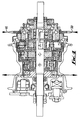
- the hub gear includes a hub spindle 1 which is provided with flats at at least one end of the spindle to allow the spindle to be non-rotatably fixed to the frame of a bicycle with the appropriate washers and nuts and three epicyclic gear modules A, B and C which will be described in more detail later. These are identified in order of increasing gear ratio.
- the three modules A, C and B respectively comprise three sun gears 5,16,19 which are capable of being non-rotatably locked and unlocked with respect to the hub spindle 1.
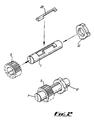
- Figure 3 further shows ratchet pawl gear selector 28 of module A which is one way of achieving this non-rotatable locking means for sun gear 5 of module A.
- the ratchet pawl gear selector 28 has two working ends providing a sun gear locking pawl 29 and a cam plate pawl 30 and seats in hub spindle recess 33.
- Sun gear locking pawl 29 works to non-rotatably lock and unlock the sun gear 5 of module A with respect to the hub spindle 1 in the manner shown in figure 6 where the sun gear locking pawl 29 is resiliently urged into contact with the internal ratchet form of sun gear 5 by ratchet pawl gear selector springs 31 which seat in holes 31 a.
- Cam plate pawl 30 works with the internal cam form on cam plate 41 to move the sun gear locking pawl 29 to the appropriate position to achieve the desired gear selection.
- Figure 5 shows cam plate 41 in a position that allows the cam plate pawl 30 to rotate in a clockwise direction under action of the selector springs 31.
- ratchet pawl gear selectors 28, 47 and 48 fitted to the hub spindle 1. Only one ratchet pawl gear selector 28 is shown on figure 3. This works to non-rotatably lock sun gear 5 in module A to the hub spindle 1 under the action of cam plate 41.
- the other two ratchet pawl gear selectors are not shown in figure 3 but differ in length and are arranged around the circumference of the hub spindle as shown in figure 5.
- Ratchet pawl gear selector 47 works to non-rotatably lock sun gear 19 of module B to the hub spindle 1 under the action of cam plate 39.
- Ratchet pawl gear selector 48 works to non-rotatably lock sun gear 16 to the hub spindle 1 under the action of cam plate 40.
- the distance and angle between the sun gear locking pawl 29 and the cam plate pawl 30 are fixed to each other as part of the ratchet pawl gear selector 28 of module A. This means that movement of the cam plate pawl 30 will directly move the sun gear pawl 29.
- the example shows two ratchet pawl gear selector springs 31 resiliently loading the sun gear locking pawl 29 and the cam plate pawl 30, it may only be necessary to resiliently load the sun gear locking pawl or the cam plate pawl as the pawls are integral parts of the selector 28.
- the pawls could be separate but connected and separately resiliently loaded.
- the hub gear further includes four planet cage plates and three gear rings:
- planet cage plate input 4 and planet cage plate 9 are fixed together at a set distance apart with rivets 14 the set distance being controlled by the planet pinion pins 7.
- sun gear 5 planet pinions 6, planet cage pawls 12 and planet cage pawl springs 11 are arranged as indicated in figure 3 to create epicyclic gear module 'A'.
- planet pinion pin 7 acts as both the spindle for the planet pinion 6 and the spacer to hold the planet cage plates apart.
- the gear ring 8 has internal gear teeth that mesh with the planet pinions 6 and in the example has an axial ratchet face with unidirectional gear ring pockets 13 that act with the planet cage pawls 12 to give forward drive transmission or can be over-ridden depending on the gear selection.
- Epicyclic gear module 'C' is adjacent to epicyclic gear module 'A' because this arrangement allows a hub shell with a smaller envelope to be used.
- Module A is the largest module, module C the next largest and module B the smallest in terms of physical size.
- the epicyclic gear module 'C' is constructed in a similar manner to epicyclic gear module 'A'.
- the gear ring 8 and the planet cage plate 17 are fixed together at a set distance apart using rivets, and planet pinion pins, (both not shown) in the same manner as before.
- sun gear 16 planet pinions 15
- planet cage pawls 12c planet cage pawl springs 11c are arranged as indicated in figure 3 to create the epicyclic gear module 'C'.
- the gear ring 18 has internal gear teeth that mesh with the planet pinions 15 and in the example has an axial ratchet face with unidirectional gear ring pockets 13c that act with the planet cage pawls 12c to give forward drive transmission or can be over-ridden depending on the gear selection .
- the epicyclic gear module 'B' is constructed in a similar manner to epicyclic gear modules 'A' and 'C'.
- the gear ring 18 and the planet cage plate 20 are fixed together at a set distance apart using rivets 14b and planet pinion pins 7b in the same manner as before.
- sun gear 19 planet pinions 22 planet cage pawls 12b and planet cage pawl springs 11b are arranged as indicated in figure 3 to create epicyclic gear module 'B'.
- gear ring As described previously to fully complete this epicyclic gear train a gear ring is required. In the example described this forms the output part of the gear train.
- the gear ring 21 is rigidly attached to gear ring pawl carrier 25.
- This gear ring pawl carrier is coupled to the hub shell assembly with a unidirectional clutch. In the example shown this comprises at least one gear ring pawl 23 and a gear ring pawl spring 24.
- the gear ring 8 has internal gear teeth that mesh with the planet pinions 6 and in the example has an axial ratchet face with unidirectional gear ring pockets 13b that act with the planet cage pawls 12b to give forward drive transmission or can be over-ridden depending on the gear selection.
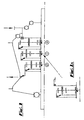
- FIG. 4 shows the drive paths through the hub for the highest gear condition and direct drive. These are respectively referenced HG and DD.
- HG and DD For the highest gear all the epicyclic gear modules are "on” and, for the direct drive "off”.
- the drive transmission path through the series of gear modules to the hub shell assembly 26 has been described previously in the text.
- the drive transmission path from the bicycle chain to the first epicyclic gear module 'A' can be described by referring to figure 3.
- Drive from the bicycle chain is transmitted into the multi-speed gear hub through a sprocket 2 which is securely fixed to a driver 3.
- the driver 3 is connected to the planet cage plate input 4 of epicyclic gear module 'A' with a driver/planet cage coupling 10.
- the driver/planet cage coupling 10 can be in the form of a 'dog clutch' and works to transmit the drive transmission from the driver 3 to the planet cage plate input 4.
- Gear changing at the hub is achieved by rotation of a cable drum 45.
- This cable drum is rotated in a series of steps by a control and cable combination in a similar manner to other types of gear hubs, for bicycles, currently available.
- the cable drum 45 is securely fixed to a gear change cone 36.
- This gear change cone 36 is supported on and can rotate freely on a support cone 46 with the aid of angular contact ball bearings in a manner known in the art for the construction of bicycle gear hubs.
- the gear change cone 36 also supports the driver 3 in a similar way on angular contact ball bearings again in the manner known in the art for the construction of bicycle gear hubs.
- the gear change cone 36 can freely rotate between the support cone 46 and the driver 3.
- the gear change cone 36 has a gear change cone/cam housing coupling 37 formed in the bore which is coupled to a cam plate housing 38 so that rotation of the gear change cone 36 can be directly transmitted to the cam plate housing 38.
- the cam plate housing 38 also has a spline form in its bore that allows cam plates 39, 40 and 41 to be assembled inside the cam plate housing 38 in required order to match the mating ratchet pawl gear selectors 28, 47 and 48. This spline form transmits rotation of the cam plate housing to the cam plates 39, 40 and 41.
- cam plate housing 38 and the cam plates 39, 40 and 41 are free to rotate on the hub spindle and the axial position of these items is controlled by the hub spindle flange 32. Therefore in the manner described the rotation from the cable drum 45 is transmitted to the cam plates 39,40 and 41.
- Figure 5 shows in section the operation of the cam plates 39, 40 and 41 in one particular gear.
- the internal cam forms of cam plates 39 and 40 are in such a position to hold the respective ratchet pawl gear selectors 47 and 48 down within the circumference of hub spindle 1. This makes the ratchet pawl gear selectors 47 and 48 inoperative allowing the respective sun gears 19 and 16 to rotate freely on the hub spindle 1.
- the internal cam form of cam plate 41 has allowed the ratchet pawl gear selector 28 to rotate in a clockwise direction under the action of ratchet pawl gear selector spring 31 so that the cam plate pawl is extended outwards from the centre of the hub spindle 1. This allows the sun pinion locking pawl 29 to lock the sun pinion 5 to the hub spindle 1 in the manner shown in figure 6.
- the control and cable combination can rotate the cable drum 45 in one direction only.
- a torsion spring 34 which is secured on the hub spindle 1 with a torsion spring cup 35 and acts on the gear change cone 36 so that the torsion spring 34 is tensioned when the cable moves the cable drum 45 so that the tension stored in the torsion spring acts to return the cable drum when the tension in the cable is released.
- an adjustment cover 44 which is secured to the hub spindle 1 with locknut 43 and this allows. the starting position of the control and cable combination to be adjusted to match the starting position of the cable drum.
- the three module arrangement described above enables eight speeds to be provided for as already described.
Landscapes
- Engineering & Computer Science (AREA)
- Chemical & Material Sciences (AREA)
- Combustion & Propulsion (AREA)
- Transportation (AREA)
- Mechanical Engineering (AREA)
- Structure Of Transmissions (AREA)
- Transmission Devices (AREA)
Description
| GEAR | GEAR MODULE 'A' | GEAR MODULE 'B' |
| 1 | OFF | OFF |
| 2 | ON | OFF |
| 3 | OFF | ON |
| 4 | ON | ON |
| GEAR | GEAR MODULE | GEAR MODULE | GEAR MODULE |
| 'A' | 'B' | 'C' | |
| 1 | OFF | OFF | OFF |
| 2 | ON | OFF | OFF |
| 3 | OFF | ON | OFF |
| 4 | OFF | OFF | ON |
| 5 | ON | ON | |
| 6 | ON | OFF | ON |
| 7 | OFF | ON | ON |
| 8 | ON | ON | ON |
| GEAR | GEAR MODULE 'A' RATIO=1.280 OR 1 | GEAR MODULE 'B' RATIO=1.45O OR 1 | GEAR MODULE 'C' RATIO=1.644 OR 1 | TOTAL RATIO | GEAR STEP |
| 1 | 1 | 1 | 1 | 1 | |
| 2 | 1.280 | 1 | 1 | 1.280 | +28% |
| 3 | 1 | 1.45 | 1 | 1.450 | +13% |
| 4 | 1 | 1 | 1.644 | 1.644 | +13% |
| 5 | 1.280 | 1.45 | 1 | 1.856 | +13% |
| 6 | 1.280 | 1 | 1.644 | 2.104 | +13% |
| 7 | 1 | 1.45 | 1.644 | 2.384 | +13% |
| 8 | 1.280 | 1.45 | 1.644 | 3.051 | +28% |
- All the gear selections are performed in the spindle assembly. There is no need to have a clutch as used in previous three, five and seven speed hubs known in the art.
- The hub gear will always have positive drive i.e. no neutral position.
- More than one sun pinion can be selected at any one time without damage occurring as this is a normal condition for the hub gear.
- Modular construction allows for easier manufacture and more common parts that can be used in different gear hubs. For example a four speed hub could be constructed using gear modules 'A' and 'C' from the eight speed example described earlier.
| GEAR | GEAR MODULE 'A' RATIO = 1.280 OR 1 | GEAR MODULE 'C' RATIO = 1.644 OR 1 | TOTAL RATIO | GEAR STEP |
| 1 | 1 | 1 | 1 | |
| 2 | 1.280 | 1 | 1.280 | + 28% |
| 3 | 1 | 1.644 | 1.644 | + 28% |
| 4 | 1.280 | 1.644 | 2.104 | + 28% |
Claims (14)
- A multi-speed hub gear comprising a hub spindle (1), two or more modules (A,B and C) operatively connected in series on the hub spindle (1), each module including a sun gear (5,16,19), a planet cage (9,20,17), planet pinions (6,15,22) mounted in the cage and meshing with the sun gear, and a gear ring (8,21,18) meshing with the planet pinions, means (29) for selectively locking and unlocking the sun gear non-rotatably with respect to the hub spindle in order to provide a plurality of gear ratios depending upon the number of modules and characterised by a one-way clutch coupling the planet cage (9,20,17) to the gear ring (8,21,18) such that there is a always positive drive:
- A multi-speed hub gear as claimed in claim 1, in which an input to the hub gear drives a first module(A), the output from the first module driving the next module (C).
- A multi-speed hub gear as claimed in claim 1 or 2, in which the means (29) for selectively locking and unlocking the sun gear (5) selectively provides either direct drive or a gear ratio in the corresponding module (A).
- A multi-speed hub gear as claimed in. claim 1, 2, or 3, in which the last module (C) in the series of modules drives a hub shell.
- A multi-speed hub gear as claimed in claim 4, in which the hub shell is driven by means of radially or axially movable pawls (23) mounted in the gear module (A) and cooperable with ratchet teeth provided in the hub shell assembly.
- A multi-speed hub gear as claimed in any preceding claim, in which each epicyclic gear module (A,B and C) is arranged such that the planet cage (9,20,17) is the driving or input component and the one-way clutch is arranged so that direct drive transmission can be achieved when the sun pinion (5) is unlocked in the rotational sense with respect to the hub spindle (1).
- A multi-speed hub gear as claimed in claim 6, in which the first epicyclic gear module (A) drives the next epicyclic gear module (C) directly when the sun gear (5) is unlocked with respect to the spindle with no increase or decrease in gear ratio.
- A multi-speed hub gear as claimed in any preceding claim, in which the gear ratio of each gear module (A,B and C) is the same or different to provide a number of different gear ratios.
- A multi-speed hub gear as claimed in any preceding claim, in which the means for non-rotatably locking and unlocking the sun gear (5) with respect to the hub spindle (1) comprises a ratchet pawl (29) which is operative to lock in the same direction as the forward rotation of the hub gear assembly and to allow the hub gear to be rotated backwards.
- A multi-speed hub gear as claimed in any preceding claim, in which each gear module (A,B,C) can be selected independently by a ratchet pawl gear selector (28, 47, 48).
- A multi-speed hub gear as claimed in claim 10, in which one end of the selector (28) works to non-rotatably lock or unlock the sun gear (5) to the hub spindle (1).
- A multi-speed hub gear as claimed in claim 11, in which the other end (30) of the selector (28) is located inside a cam plate (41 ) in the form of a ring placed around the circumference of the hub spindle (1) with a cam form on the inside and a spline form on the outside so that the cam plate (41) can be rotated with respect to the hub spindle (1).
- A multi-speed hub gear as claimed in claim 12, in which the ratchet pawl gear selector (28) is located in the hub spindle (1) and is resiliently urged into contact with the sun gear (5) and the cam plate (41).
- A multi-speed hubgear as claimed in any of claims 1 to 5 in which at least one epicyclic gear module (A, B and C) is arranged such that the gear ring (8,21,18) is the driving or input component and the planet cage (9,20,17) is the output member.
Applications Claiming Priority (3)
| Application Number | Priority Date | Filing Date | Title |
|---|---|---|---|
| GB0012873 | 2000-05-27 | ||
| GBGB0012873.6A GB0012873D0 (en) | 2000-05-27 | 2000-05-27 | A multi speed hub gear |
| PCT/GB2001/002320 WO2001092094A1 (en) | 2000-05-27 | 2001-05-25 | A multi-speed hub gear |
Publications (3)
| Publication Number | Publication Date |
|---|---|
| EP1289827A1 EP1289827A1 (en) | 2003-03-12 |
| EP1289827B1 true EP1289827B1 (en) | 2005-05-04 |
| EP1289827B2 EP1289827B2 (en) | 2009-04-22 |
Family
ID=9892457
Family Applications (1)
| Application Number | Title | Priority Date | Filing Date |
|---|---|---|---|
| EP01934141A Expired - Lifetime EP1289827B2 (en) | 2000-05-27 | 2001-05-25 | A multi-speed hub gear |
Country Status (7)
| Country | Link |
|---|---|
| EP (1) | EP1289827B2 (en) |
| JP (1) | JP4588284B2 (en) |
| CN (1) | CN1231388C (en) |
| AU (1) | AU2001260447A1 (en) |
| DE (1) | DE60110585T3 (en) |
| GB (1) | GB0012873D0 (en) |
| WO (1) | WO2001092094A1 (en) |
Cited By (2)
| Publication number | Priority date | Publication date | Assignee | Title |
|---|---|---|---|---|
| EP2020375B2 (en) † | 2007-08-01 | 2014-09-24 | Shimano Inc. | Hub transmission for a bicycle |
| US11541964B2 (en) * | 2018-03-28 | 2023-01-03 | Wilfried Donner | Multi-speed transmission with two planetary gears |
Families Citing this family (13)
| Publication number | Priority date | Publication date | Assignee | Title |
|---|---|---|---|---|
| JP2008510104A (en) * | 2004-08-12 | 2008-04-03 | モノトルク リミテッド | Internal mechanism type automatic transmission assembly |
| WO2008051014A1 (en) * | 2006-10-24 | 2008-05-02 | Dong Hwan Byun | Planetary gear transmission and vehicle using same |
| DE602007004313D1 (en) * | 2007-06-29 | 2010-03-04 | Shimano Kk | Hub gear for a bicycle |
| DE602007013202D1 (en) * | 2007-07-18 | 2011-04-28 | Shimano Kk | Hub gear for a bicycle |
| US20120071290A1 (en) * | 2009-05-26 | 2012-03-22 | Donghwan Byun | Multistage transmission |
| JP2012528285A (en) * | 2009-05-26 | 2012-11-12 | ビョン、ドンファン | Multi-stage gear transmission |
| US8439792B2 (en) * | 2010-01-20 | 2013-05-14 | The Gates Corporation | Planetary gear mechanism for a bicycle |
| TWI565622B (en) * | 2015-01-05 | 2017-01-11 | The lever control system of the internal transmission control mechanism | |
| CN105134938B (en) * | 2015-08-18 | 2017-09-22 | 李激初 | A kind of intelligent transmission and the motor control method used |
| WO2018212406A1 (en) | 2017-05-19 | 2018-11-22 | 김복성 | Multi-speed transmission of motor for transportation means |
| DE102018208382B4 (en) * | 2018-05-28 | 2025-04-30 | Zf Friedrichshafen Ag | Planetary bottom bracket gear for a bicycle or pedelec |
| EP4234384B1 (en) * | 2022-02-23 | 2025-07-09 | New Kailung Gear Co., Ltd. | Gear switching control device of an internal derailleur |
| TWI802387B (en) * | 2022-04-25 | 2023-05-11 | 日馳企業股份有限公司 | Bicycle derailleur |
Family Cites Families (13)
| Publication number | Priority date | Publication date | Assignee | Title |
|---|---|---|---|---|
| GB190523232A (en) † | 1905-11-11 | 1906-09-27 | George Douglas Leechman | Improvements in or relating to Variable Speed Gearing |
| GB190629217A (en) † | 1906-12-22 | 1907-12-19 | Charles Thomas Brock Sangster | Improvements in Three-speed Change Gears, principally for use in connection with the Hubs of Cycles. |
| GB190629216A (en) † | 1906-12-22 | 1907-12-19 | Charles Thomas Brock Sangster | Improvements in Three-speed Gears for Cycles and other Vehicles |
| GB190703414A (en) † | 1907-02-11 | 1908-02-11 | Rudge Whitworth Ltd | Improvements in and relating to Variable Speed Epicyclic Gears |
| GB190711315A (en) † | 1907-05-15 | 1908-04-23 | Arthur Alltree | Improvements in and relating to Variable Speed Gears for Cycles and the like. |
| US4858494A (en) * | 1988-05-02 | 1989-08-22 | Healy Donald B | Torque responsive automatic shifting hub |
| US4926713A (en) * | 1989-03-15 | 1990-05-22 | H.V.T. Technology Ltd. | Multiple gear-ratio automatic transmission |
| GB9304189D0 (en) | 1993-03-02 | 1993-04-21 | Sturmey Archer Ltd | Epicyclic change speed gear hubs |
| DE4415266C1 (en) † | 1994-04-30 | 1995-08-10 | Fichtel & Sachs Ag | Gear change mechanism for multi-speed bicycle hub |
| GB9409844D0 (en) | 1994-05-17 | 1994-07-06 | Sturmey Archer Ltd | An epicyclic change gear system |
| GB9726521D0 (en) | 1997-12-17 | 1998-02-11 | Sturmey Archer Ltd | Improvements in or relating to multi-speed hub gears |
| JP2000283251A (en) * | 1999-03-31 | 2000-10-13 | Honda Motor Co Ltd | Power transmission device with planetary gear device |
| KR100436697B1 (en) † | 1999-12-15 | 2004-06-22 | 오종수 | Apparatus for changing speed of bicycles |
-
2000
- 2000-05-27 GB GBGB0012873.6A patent/GB0012873D0/en not_active Ceased
-
2001
- 2001-05-25 DE DE60110585T patent/DE60110585T3/en not_active Expired - Lifetime
- 2001-05-25 CN CN01810236.0A patent/CN1231388C/en not_active Expired - Lifetime
- 2001-05-25 EP EP01934141A patent/EP1289827B2/en not_active Expired - Lifetime
- 2001-05-25 JP JP2001588077A patent/JP4588284B2/en not_active Expired - Lifetime
- 2001-05-25 AU AU2001260447A patent/AU2001260447A1/en not_active Abandoned
- 2001-05-25 WO PCT/GB2001/002320 patent/WO2001092094A1/en not_active Ceased
Cited By (2)
| Publication number | Priority date | Publication date | Assignee | Title |
|---|---|---|---|---|
| EP2020375B2 (en) † | 2007-08-01 | 2014-09-24 | Shimano Inc. | Hub transmission for a bicycle |
| US11541964B2 (en) * | 2018-03-28 | 2023-01-03 | Wilfried Donner | Multi-speed transmission with two planetary gears |
Also Published As
| Publication number | Publication date |
|---|---|
| DE60110585D1 (en) | 2005-06-09 |
| EP1289827B2 (en) | 2009-04-22 |
| JP4588284B2 (en) | 2010-11-24 |
| WO2001092094A1 (en) | 2001-12-06 |
| DE60110585T3 (en) | 2009-11-05 |
| EP1289827A1 (en) | 2003-03-12 |
| GB0012873D0 (en) | 2000-07-19 |
| CN1231388C (en) | 2005-12-14 |
| JP2003534981A (en) | 2003-11-25 |
| AU2001260447A1 (en) | 2001-12-11 |
| DE60110585T2 (en) | 2006-01-19 |
| CN1431962A (en) | 2003-07-23 |
Similar Documents
| Publication | Publication Date | Title |
|---|---|---|
| EP1289827B2 (en) | A multi-speed hub gear | |
| EP2017175B1 (en) | Hub transmission for a bicycle | |
| US20220402574A1 (en) | Transmission system | |
| DE102012109637B4 (en) | Bicycle drive unit | |
| EP3615826B1 (en) | Clutch system for a torque transmission | |
| EP2020375B1 (en) | Hub transmission for a bicycle | |
| CN107399407B (en) | Multi-speed internally geared hub with selectively fixed gear | |
| EP2426041B1 (en) | Power-assisted bicycle including regenerative mechanism | |
| US9822844B2 (en) | Shifting device and gear unit | |
| US11541964B2 (en) | Multi-speed transmission with two planetary gears | |
| NO334279B1 (en) | gearshift | |
| US6312355B1 (en) | Bicycle transmission that shifts when a driver is in a predetermined rotational position | |
| WO2012066124A1 (en) | Drive unit | |
| WO2020130842A1 (en) | A pedally propelled vehicle multi-speed gear system | |
| EP2008927B1 (en) | Hub transmission for a bicycle | |
| CN102092455A (en) | Multi-speed driving gear hub for bicycles | |
| EP1452438B1 (en) | An internal hub transmission for a bicycle | |
| US4726258A (en) | Dual transmission system and its power shift mechanism | |
| JPH0710069A (en) | Interior shifting hub for bicycles | |
| EP1452437B2 (en) | An internal hub transmission for a bicycle | |
| US12296919B2 (en) | Bottom bracket gear mechanism of planetary design for a bicycle or a pedelec | |
| US12337931B2 (en) | Bottom bracket gear mechanism of planetary design for a bicycle or a pedelec | |
| US12428105B2 (en) | Planetary-type bottom-bracket transmission for a bicycle or a pedelec | |
| CN101568750A (en) | Planetary gear transmission device and vehicle using same |
Legal Events
| Date | Code | Title | Description |
|---|---|---|---|
| PUAI | Public reference made under article 153(3) epc to a published international application that has entered the european phase |
Free format text: ORIGINAL CODE: 0009012 |
|
| 17P | Request for examination filed |
Effective date: 20021218 |
|
| AK | Designated contracting states |
Kind code of ref document: A1 Designated state(s): AT BE CH CY DE DK ES FI FR GB GR IE IT LI LU MC NL PT SE TR |
|
| AX | Request for extension of the european patent |
Extension state: AL LT LV MK RO SI |
|
| 17Q | First examination report despatched |
Effective date: 20031114 |
|
| RBV | Designated contracting states (corrected) |
Designated state(s): DE DK NL |
|
| GRAP | Despatch of communication of intention to grant a patent |
Free format text: ORIGINAL CODE: EPIDOSNIGR1 |
|
| GRAS | Grant fee paid |
Free format text: ORIGINAL CODE: EPIDOSNIGR3 |
|
| GRAA | (expected) grant |
Free format text: ORIGINAL CODE: 0009210 |
|
| AK | Designated contracting states |
Kind code of ref document: B1 Designated state(s): DE DK NL |
|
| RAP1 | Party data changed (applicant data changed or rights of an application transferred) |
Owner name: SUNRACE STURMEY-ARCHER INC. |
|
| REG | Reference to a national code |
Ref country code: IE Ref legal event code: FG4D |
|
| REF | Corresponds to: |
Ref document number: 60110585 Country of ref document: DE Date of ref document: 20050609 Kind code of ref document: P |
|
| PG25 | Lapsed in a contracting state [announced via postgrant information from national office to epo] |
Ref country code: DK Free format text: LAPSE BECAUSE OF FAILURE TO SUBMIT A TRANSLATION OF THE DESCRIPTION OR TO PAY THE FEE WITHIN THE PRESCRIBED TIME-LIMIT Effective date: 20050804 |
|
| PLBI | Opposition filed |
Free format text: ORIGINAL CODE: 0009260 |
|
| PLAX | Notice of opposition and request to file observation + time limit sent |
Free format text: ORIGINAL CODE: EPIDOSNOBS2 |
|
| 26 | Opposition filed |
Opponent name: SRAM DEUTSCHLAND GMBH Effective date: 20060202 |
|
| NLR1 | Nl: opposition has been filed with the epo |
Opponent name: SRAM DEUTSCHLAND GMBH |
|
| PLAF | Information modified related to communication of a notice of opposition and request to file observations + time limit |
Free format text: ORIGINAL CODE: EPIDOSCOBS2 |
|
| PLBB | Reply of patent proprietor to notice(s) of opposition received |
Free format text: ORIGINAL CODE: EPIDOSNOBS3 |
|
| PLAB | Opposition data, opponent's data or that of the opponent's representative modified |
Free format text: ORIGINAL CODE: 0009299OPPO |
|
| R26 | Opposition filed (corrected) |
Opponent name: SRAM DEUTSCHLAND GMBH Effective date: 20060202 |
|
| NLR1 | Nl: opposition has been filed with the epo |
Opponent name: SRAM DEUTSCHLAND GMBH |
|
| PUAH | Patent maintained in amended form |
Free format text: ORIGINAL CODE: 0009272 |
|
| STAA | Information on the status of an ep patent application or granted ep patent |
Free format text: STATUS: PATENT MAINTAINED AS AMENDED |
|
| 27A | Patent maintained in amended form |
Effective date: 20090422 |
|
| AK | Designated contracting states |
Kind code of ref document: B2 Designated state(s): DE DK NL |
|
| NLR2 | Nl: decision of opposition |
Effective date: 20090422 |
|
| NLR3 | Nl: receipt of modified translations in the netherlands language after an opposition procedure | ||
| PGFP | Annual fee paid to national office [announced via postgrant information from national office to epo] |
Ref country code: DE Payment date: 20200605 Year of fee payment: 20 Ref country code: NL Payment date: 20200520 Year of fee payment: 20 |
|
| REG | Reference to a national code |
Ref country code: DE Ref legal event code: R071 Ref document number: 60110585 Country of ref document: DE |
|
| REG | Reference to a national code |
Ref country code: NL Ref legal event code: MK Effective date: 20210524 |