EP1291124A1 - Device for loading and unloading tools into/from the tool magazine of a machine-tool - Google Patents
Device for loading and unloading tools into/from the tool magazine of a machine-tool Download PDFInfo
- Publication number
- EP1291124A1 EP1291124A1 EP02013796A EP02013796A EP1291124A1 EP 1291124 A1 EP1291124 A1 EP 1291124A1 EP 02013796 A EP02013796 A EP 02013796A EP 02013796 A EP02013796 A EP 02013796A EP 1291124 A1 EP1291124 A1 EP 1291124A1
- Authority
- EP
- European Patent Office
- Prior art keywords
- tool
- aforesaid
- drawer
- oscillating
- wall
- Prior art date
- Legal status (The legal status is an assumption and is not a legal conclusion. Google has not performed a legal analysis and makes no representation as to the accuracy of the status listed.)
- Granted
Links
- 238000003754 machining Methods 0.000 claims description 38
- 239000002184 metal Substances 0.000 claims description 3
- 230000008878 coupling Effects 0.000 description 4
- 238000010168 coupling process Methods 0.000 description 4
- 238000005859 coupling reaction Methods 0.000 description 4
- 238000004519 manufacturing process Methods 0.000 description 3
- 238000000034 method Methods 0.000 description 2
- 230000010355 oscillation Effects 0.000 description 2
- 238000002485 combustion reaction Methods 0.000 description 1
- 238000010276 construction Methods 0.000 description 1
- 238000006073 displacement reaction Methods 0.000 description 1
- 230000002093 peripheral effect Effects 0.000 description 1
- 230000001681 protective effect Effects 0.000 description 1
- 238000003466 welding Methods 0.000 description 1
Images


Classifications
-
- B—PERFORMING OPERATIONS; TRANSPORTING
- B23—MACHINE TOOLS; METAL-WORKING NOT OTHERWISE PROVIDED FOR
- B23Q—DETAILS, COMPONENTS, OR ACCESSORIES FOR MACHINE TOOLS, e.g. ARRANGEMENTS FOR COPYING OR CONTROLLING; MACHINE TOOLS IN GENERAL CHARACTERISED BY THE CONSTRUCTION OF PARTICULAR DETAILS OR COMPONENTS; COMBINATIONS OR ASSOCIATIONS OF METAL-WORKING MACHINES, NOT DIRECTED TO A PARTICULAR RESULT
- B23Q3/00—Devices holding, supporting, or positioning work or tools, of a kind normally removable from the machine
- B23Q3/155—Arrangements for automatic insertion or removal of tools, e.g. combined with manual handling
- B23Q3/1552—Arrangements for automatic insertion or removal of tools, e.g. combined with manual handling parts of devices for automatically inserting or removing tools
- B23Q3/15526—Storage devices; Drive mechanisms therefor
- B23Q3/15533—Storage devices; Drive mechanisms therefor combined with manual tool transfers
-
- B—PERFORMING OPERATIONS; TRANSPORTING
- B23—MACHINE TOOLS; METAL-WORKING NOT OTHERWISE PROVIDED FOR
- B23Q—DETAILS, COMPONENTS, OR ACCESSORIES FOR MACHINE TOOLS, e.g. ARRANGEMENTS FOR COPYING OR CONTROLLING; MACHINE TOOLS IN GENERAL CHARACTERISED BY THE CONSTRUCTION OF PARTICULAR DETAILS OR COMPONENTS; COMBINATIONS OR ASSOCIATIONS OF METAL-WORKING MACHINES, NOT DIRECTED TO A PARTICULAR RESULT
- B23Q11/00—Accessories fitted to machine tools for keeping tools or parts of the machine in good working condition or for cooling work; Safety devices specially combined with or arranged in, or specially adapted for use in connection with, machine tools
- B23Q11/08—Protective coverings for parts of machine tools; Splash guards
-
- B—PERFORMING OPERATIONS; TRANSPORTING
- B23—MACHINE TOOLS; METAL-WORKING NOT OTHERWISE PROVIDED FOR
- B23Q—DETAILS, COMPONENTS, OR ACCESSORIES FOR MACHINE TOOLS, e.g. ARRANGEMENTS FOR COPYING OR CONTROLLING; MACHINE TOOLS IN GENERAL CHARACTERISED BY THE CONSTRUCTION OF PARTICULAR DETAILS OR COMPONENTS; COMBINATIONS OR ASSOCIATIONS OF METAL-WORKING MACHINES, NOT DIRECTED TO A PARTICULAR RESULT
- B23Q3/00—Devices holding, supporting, or positioning work or tools, of a kind normally removable from the machine
- B23Q3/155—Arrangements for automatic insertion or removal of tools, e.g. combined with manual handling
- B23Q3/157—Arrangements for automatic insertion or removal of tools, e.g. combined with manual handling of rotary tools
- B23Q3/15713—Arrangements for automatic insertion or removal of tools, e.g. combined with manual handling of rotary tools a transfer device taking a single tool from a storage device and inserting it in a spindle
- B23Q3/1572—Arrangements for automatic insertion or removal of tools, e.g. combined with manual handling of rotary tools a transfer device taking a single tool from a storage device and inserting it in a spindle the storage device comprising rotating or circulating storing means
- B23Q3/15753—Arrangements for automatic insertion or removal of tools, e.g. combined with manual handling of rotary tools a transfer device taking a single tool from a storage device and inserting it in a spindle the storage device comprising rotating or circulating storing means the storage means rotating or circulating in a plane perpendicular to the axis of the spindle
- B23Q3/15766—Arrangements for automatic insertion or removal of tools, e.g. combined with manual handling of rotary tools a transfer device taking a single tool from a storage device and inserting it in a spindle the storage device comprising rotating or circulating storing means the storage means rotating or circulating in a plane perpendicular to the axis of the spindle the axis of the stored tools being arranged perpendicularly to the rotating or circulating plane of the storage means
-
- F—MECHANICAL ENGINEERING; LIGHTING; HEATING; WEAPONS; BLASTING
- F16—ENGINEERING ELEMENTS AND UNITS; GENERAL MEASURES FOR PRODUCING AND MAINTAINING EFFECTIVE FUNCTIONING OF MACHINES OR INSTALLATIONS; THERMAL INSULATION IN GENERAL
- F16P—SAFETY DEVICES IN GENERAL; SAFETY DEVICES FOR PRESSES
- F16P1/00—Safety devices independent of the control and operation of any machine
-
- Y—GENERAL TAGGING OF NEW TECHNOLOGICAL DEVELOPMENTS; GENERAL TAGGING OF CROSS-SECTIONAL TECHNOLOGIES SPANNING OVER SEVERAL SECTIONS OF THE IPC; TECHNICAL SUBJECTS COVERED BY FORMER USPC CROSS-REFERENCE ART COLLECTIONS [XRACs] AND DIGESTS
- Y10—TECHNICAL SUBJECTS COVERED BY FORMER USPC
- Y10T—TECHNICAL SUBJECTS COVERED BY FORMER US CLASSIFICATION
- Y10T483/00—Tool changing
- Y10T483/11—Tool changing with safety means
- Y10T483/115—Guard
-
- Y—GENERAL TAGGING OF NEW TECHNOLOGICAL DEVELOPMENTS; GENERAL TAGGING OF CROSS-SECTIONAL TECHNOLOGIES SPANNING OVER SEVERAL SECTIONS OF THE IPC; TECHNICAL SUBJECTS COVERED BY FORMER USPC CROSS-REFERENCE ART COLLECTIONS [XRACs] AND DIGESTS
- Y10—TECHNICAL SUBJECTS COVERED BY FORMER USPC
- Y10T—TECHNICAL SUBJECTS COVERED BY FORMER US CLASSIFICATION
- Y10T483/00—Tool changing
- Y10T483/16—Tool changing with means to transfer work
-
- Y—GENERAL TAGGING OF NEW TECHNOLOGICAL DEVELOPMENTS; GENERAL TAGGING OF CROSS-SECTIONAL TECHNOLOGIES SPANNING OVER SEVERAL SECTIONS OF THE IPC; TECHNICAL SUBJECTS COVERED BY FORMER USPC CROSS-REFERENCE ART COLLECTIONS [XRACs] AND DIGESTS
- Y10—TECHNICAL SUBJECTS COVERED BY FORMER USPC
- Y10T—TECHNICAL SUBJECTS COVERED BY FORMER US CLASSIFICATION
- Y10T483/00—Tool changing
- Y10T483/17—Tool changing including machine tool or component
- Y10T483/1702—Rotating work machine tool [e.g., screw machine, lathe, etc.]
- Y10T483/1714—Tool changer between tool support and matrix
- Y10T483/1719—Tool support comprises turret
- Y10T483/1721—Linearly moveable tool changer
-
- Y—GENERAL TAGGING OF NEW TECHNOLOGICAL DEVELOPMENTS; GENERAL TAGGING OF CROSS-SECTIONAL TECHNOLOGIES SPANNING OVER SEVERAL SECTIONS OF THE IPC; TECHNICAL SUBJECTS COVERED BY FORMER USPC CROSS-REFERENCE ART COLLECTIONS [XRACs] AND DIGESTS
- Y10—TECHNICAL SUBJECTS COVERED BY FORMER USPC
- Y10T—TECHNICAL SUBJECTS COVERED BY FORMER US CLASSIFICATION
- Y10T483/00—Tool changing
- Y10T483/17—Tool changing including machine tool or component
- Y10T483/1733—Rotary spindle machine tool [e.g., milling machine, boring, machine, grinding machine, etc.]
- Y10T483/179—Direct tool exchange between spindle and matrix
- Y10T483/1793—Spindle comprises tool changer
- Y10T483/1795—Matrix indexes selected tool to transfer position
-
- Y—GENERAL TAGGING OF NEW TECHNOLOGICAL DEVELOPMENTS; GENERAL TAGGING OF CROSS-SECTIONAL TECHNOLOGIES SPANNING OVER SEVERAL SECTIONS OF THE IPC; TECHNICAL SUBJECTS COVERED BY FORMER USPC CROSS-REFERENCE ART COLLECTIONS [XRACs] AND DIGESTS
- Y10—TECHNICAL SUBJECTS COVERED BY FORMER USPC
- Y10T—TECHNICAL SUBJECTS COVERED BY FORMER US CLASSIFICATION
- Y10T483/00—Tool changing
- Y10T483/18—Tool transfer to or from matrix
- Y10T483/1818—Matrix including means to project tool for transfer
- Y10T483/1827—Rectilinear
Definitions
- the present invention relates to any type of machine-tool, machining station or centre or the like of the type comprising:
- Machines of the type referred to above are, for example, used for machining lines, for instance, production lines for engine parts for motor vehicles, such as cylinder heads.
- the tool magazine for instance, in the form of a rotary wheel carrying along its periphery a plurality of tool-bearing seats, is periodically supplied with new tools as replacements for tools that have previously been used, for example, on account of failure or wear, or also following upon the need to change the type of machining operation to be carried out.
- the operation of replacing one or more tools in the corresponding positions in the tool magazine is performed manually. However, this operation is frequently somewhat inconvenient, on account of the limited spaces available around the magazine, and also entails safety problems for the operator.
- the purpose of the present invention is to overcome the aforesaid drawbacks by enabling loading of a new tool into the tool magazine or unloading of a tool from the magazine with extremely simple, easy and fast operations and with total safety for the operator.
- the subject of the invention is a device for loading and unloading tools into/from the tool magazine of a machine-tool of the type referred to at the beginning of this description, characterized in that the aforesaid protection wall has an opening for access to the working area of the machining head, and in that said device further comprises an oscillating drawer having two walls that are set at an angle to one another and are mounted oscillating on said protection wall between a first position, in which one of said two walls of the drawer obstructs the access opening, and a second position, in which the other wall of the drawer obstructs the access opening, said drawer further comprising receiving and supporting means for a tool, which are arranged between the two aforesaid walls set at an angle to one another, in such a way that, in the aforesaid first position of the oscillating drawer, the aforesaid tool-bearing means are set on the outside of the protection wall, whereas, in the afores
- the operator when the drawer is in its first position, the operator can load, conveniently and in maximum safety, a new tool that is to be loaded into the tool magazine, setting it on the aforesaid tool-bearing means. Once this operation has been carried out, the operator simply has to cause oscillation of the drawer into its aforesaid second position, so as to bring the new tool loaded on the inside of the protection wall, whilst safety of the operator always remains ensured, in so far as the access opening is in any case kept obstructed by the drawer.
- the new tool is on the inside of the protection wall, it is the machining head itself which displaces until it reaches the said new tool, so as to be able to pick it up, then to displace into a position corresponding to a position of the tool magazine in order to deposit the new tool thus picked up in said position in the magazine.
- the movements of the machining head are of course controlled by an electronic control system. It is equally evident that the machining head is able to pick up a tool from the magazine and bring it onto the tool-bearing means of the oscillating drawer, after said means have been pre-set on the inside of protection wall in an empty condition.
- the aforesaid oscillating drawer is manually controlled.
- a handle for gripping On the side of the drawer, which always remains outside the protection wall, there is preferably provided a handle for gripping.
- the aforementioned tool-bearing means with which the door is equipped can be made, in a way in itself known, in the form of elastic grippers or clamps, which ensure temporary stable support of the tool until it is clamped by the spindle of the machining head and removed form the said grippers.
- the reference number 1 designates, as a whole, a machining unit for removal of stock, comprising a machining head 2, which carries a rotating spindle 3, on which a tool is to be connected in rotation.
- a workpiece-holding structure 4 Secured to the fixed structure 1 of the machine, is a workpiece-holding structure 4 of any known type, to which there is to be anchored the piece that is to undergo machining, such as the cylinder head of an internal-combustion engine.
- the piece-holding structure 4 can be mounted so that it turns about a vertical axis to enable orientation of the workpiece in a different position at the end of the machining cycle, in order to facilitate picking-up thereof by a transfer structure or a robot designed to load it onto a further machining unit of the production line.
- the machining head 2 can be displaced with respect to the fixed structure 1 along three mutually orthogonal axes in any known way.
- the machining head 2 can be displaced in a direction parallel to the axis of the spindle on a first slide, which is in turn mounted so that it can slide in a horizontal direction perpendicular to the axis of the spindle on a second slide which is mounted so that it can slide in a vertical direction on the fixed structure 1.
- the architecture of the machine-tool may also be different from what is described herein.
- the aforementioned details of the architecture of the machine are not illustrated herein, both because, as has been said, they do not fall within the scope of the invention, and because they can be made in any known way.
- the machining head 2 is accompanied, throughout its movements, by shutter gates 4, 5, 6, which completely prevent access to the structure of the machine when the latter is in operation.
- a tool magazine 7 having a wheel-like conformation, which can turn about a horizontal axis and which carries a plurality of peripheral seats 8 designed to receive and support a respective tool 9.
- a single tool is schematically illustrated.
- the working area of the machining head 3 is rendered completely inaccessible from outside, for reasons of safety, by a series of protective bars (not illustrated in Figure 1), between which there is comprised a wall 10, which has an opening 11 for access into the working area.
- a series of protective bars (not illustrated in Figure 1), between which there is comprised a wall 10, which has an opening 11 for access into the working area.
- the device according to the invention Mounted in a position corresponding to the opening 11 is the device according to the invention.
- This device is constituted by an oscillating drawer 12, which is mounted so that it oscillates about an axis 13 on the structure of the wall 10 and which comprises two plane walls 14, 15, which are mutually orthogonal and consist of metal plates.
- the two plates 14, 15 are rigidly connected together by brackets 16, 17, which also define the means for receiving and supporting a tool in the oscillating drawer 12.
- the drawer structure 12 is illustrated, at an enlarged scale and in greater detail, in Figure 2.
- the brackets 16, 17 are secured, for example by means of welding, to two plates 14a, 15a, which are fixed by means of screws to the plates 14, 15.
- the plate 15 further carries, welded thereto, a bushing 18 designed to be mounted so that it can turn about the shaft carried by the fixed structure of the machine, the said shaft defining the axis of oscillation 13 of the drawer 12.
- Figure 2 is a schematic illustration of a tool 9 set in the drawer 12.
- the tool rests on the bracket 17 and is moreover withheld by an elastic gripper or clamp 19, in itself known, carried by the bracket 16.
- the tool 9 has a shank 20 provided with means for coupling with the spindle. Also these coupling means are of a type in themselves known and consequently will not be described in further detail herein.
- the plate 15 On its outer surface, the plate 15 has a knob 21, which functions as a grip.
- the oscillating drawer 12 When it is necessary to load a new tool on the tool magazine 7, the oscillating drawer 12 is pre-set in a first position, which is not the one illustrated in Figure 1, but rather the one illustrated in Figure 3.
- the access opening 11 to the machining area is obstructed by the wall 14, which bears upon the internal surface of the wall 10.
- the wall 15 is, instead, on the outside of the wall 10, as likewise the structure of the brackets 16, 17 are on the outside of the wall 10. In this condition, the operator can deposit, conveniently and in complete safety, a tool 9 on the receiving and supporting means represented by the brackets 16, 17 and by the grippers 19.
- the machining head moves away from the oscillating drawer 12, so causing exit of the shank 20 from the gripper 19. At this point, the machining head can use the tool thus loaded directly for carrying out a machining operation, or else, more probably, unloads the tool that has been picked up into a seat on the tool magazine.
- the tool magazine can thus be supplied with new tools, whilst, at the same time, with a succession of operations that is the reverse of the one described above, the machining head can pick up a broken or worn tool from the magazine, and deposit it in the oscillating drawer 12, which has previously been set in the condition illustrated in Figure 1, after which the operator controls return of the drawer 12 manually from the advanced position to the retracted position illustrated in Figure 3, where the operator himself, in complete safety, can pick up the broken or worn tool from the gripper 19 and send it to be discarded.
- the device according to the invention is characterized by an extreme simplicity and economy of fabrication, but is, at the same time, functional and reliable, as well as guaranteeing maximum operator safety.
Landscapes
- Engineering & Computer Science (AREA)
- Mechanical Engineering (AREA)
- General Engineering & Computer Science (AREA)
- Automatic Tool Replacement In Machine Tools (AREA)
Abstract
Description
- The present invention relates to any type of machine-tool, machining station or centre or the like of the type comprising:
- a support for the piece undergoing machining;
- a machining head carrying a rotary spindle, to which there is connected in rotation a tool, said machining head being displaceable in three mutually perpendicular directions with respect to a fixed structure of the machine-tool;
- a tool magazine comprising a plurality of seats designed to receive and support respective tools, and at least one protection wall, which separates the working area of the machining head from an external protected area.
- Machines of the type referred to above are, for example, used for machining lines, for instance, production lines for engine parts for motor vehicles, such as cylinder heads. In this type of machine, the tool magazine, for instance, in the form of a rotary wheel carrying along its periphery a plurality of tool-bearing seats, is periodically supplied with new tools as replacements for tools that have previously been used, for example, on account of failure or wear, or also following upon the need to change the type of machining operation to be carried out. According to traditional techniques, the operation of replacing one or more tools in the corresponding positions in the tool magazine is performed manually. However, this operation is frequently somewhat inconvenient, on account of the limited spaces available around the magazine, and also entails safety problems for the operator.
- The purpose of the present invention is to overcome the aforesaid drawbacks by enabling loading of a new tool into the tool magazine or unloading of a tool from the magazine with extremely simple, easy and fast operations and with total safety for the operator.
- With a view to achieving the above purpose, the subject of the invention is a device for loading and unloading tools into/from the tool magazine of a machine-tool of the type referred to at the beginning of this description, characterized in that the aforesaid protection wall has an opening for access to the working area of the machining head, and in that said device further comprises an oscillating drawer having two walls that are set at an angle to one another and are mounted oscillating on said protection wall between a first position, in which one of said two walls of the drawer obstructs the access opening, and a second position, in which the other wall of the drawer obstructs the access opening, said drawer further comprising receiving and supporting means for a tool, which are arranged between the two aforesaid walls set at an angle to one another, in such a way that, in the aforesaid first position of the oscillating drawer, the aforesaid tool-bearing means are set on the outside of the protection wall, whereas, in the aforesaid second position, the aforesaid tool-bearing means are set on the inside of the protection wall.
- Thanks to the above-mentioned characteristic, when the drawer is in its first position, the operator can load, conveniently and in maximum safety, a new tool that is to be loaded into the tool magazine, setting it on the aforesaid tool-bearing means. Once this operation has been carried out, the operator simply has to cause oscillation of the drawer into its aforesaid second position, so as to bring the new tool loaded on the inside of the protection wall, whilst safety of the operator always remains ensured, in so far as the access opening is in any case kept obstructed by the drawer. Once the new tool is on the inside of the protection wall, it is the machining head itself which displaces until it reaches the said new tool, so as to be able to pick it up, then to displace into a position corresponding to a position of the tool magazine in order to deposit the new tool thus picked up in said position in the magazine. In machines of the type described above, the movements of the machining head are of course controlled by an electronic control system. It is equally evident that the machining head is able to pick up a tool from the magazine and bring it onto the tool-bearing means of the oscillating drawer, after said means have been pre-set on the inside of protection wall in an empty condition. Once this operation has been performed, the operator from outside can bring the door back into its extracted position, so as to bring the tool deposited therein onto the outside of the protection wall, where it can be unloaded in complete safety. Of course, there is nothing to rule out the possibility of the machining head, after it has picked up a new tool from the drawer, using it immediately to carry out a machining operation. It is likewise evident that, in order to pick up a tool from the drawer, the machining head must have previously unloaded the tool with which it was equipped in a position of the tool magazine.
- According to a preferred embodiment of the present invention, the aforesaid oscillating drawer is manually controlled. On the side of the drawer, which always remains outside the protection wall, there is preferably provided a handle for gripping. The aforementioned tool-bearing means with which the door is equipped can be made, in a way in itself known, in the form of elastic grippers or clamps, which ensure temporary stable support of the tool until it is clamped by the spindle of the machining head and removed form the said grippers.
- Further characteristics and advantages of the present invention will emerge from the ensuing description, with reference to the attached drawings, which are provided purely by way of non-limiting example and in which:
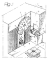
- Figure 1 is a schematic perspective view illustrating the working area of the machining head of a machine tool equipped with a device according to the invention;
- Figure 2 is a perspective view, at an enlarged scale, of the a device according to the invention, with a tool pre-set on it;
- Figure 3 is a side view of the device of Figure 2, in a different operating condition;
- Figure 4 is a top-plan view of the device in the condition illustrated in Figure 3; and
- Figure 5 is the side view of the device in the condition illustrated in Figure 3.
- In Figure 1, the
reference number 1 designates, as a whole, a machining unit for removal of stock, comprising a machining head 2, which carries a rotatingspindle 3, on which a tool is to be connected in rotation. Secured to thefixed structure 1 of the machine, is a workpiece-holding structure 4 of any known type, to which there is to be anchored the piece that is to undergo machining, such as the cylinder head of an internal-combustion engine. According to a technique in itself known, the piece-holding structure 4 can be mounted so that it turns about a vertical axis to enable orientation of the workpiece in a different position at the end of the machining cycle, in order to facilitate picking-up thereof by a transfer structure or a robot designed to load it onto a further machining unit of the production line. The machining head 2 can be displaced with respect to thefixed structure 1 along three mutually orthogonal axes in any known way. In a possible example of embodiment, the machining head 2 can be displaced in a direction parallel to the axis of the spindle on a first slide, which is in turn mounted so that it can slide in a horizontal direction perpendicular to the axis of the spindle on a second slide which is mounted so that it can slide in a vertical direction on thefixed structure 1. However, it is evident that the architecture of the machine-tool may also be different from what is described herein. Furthermore, the aforementioned details of the architecture of the machine are not illustrated herein, both because, as has been said, they do not fall within the scope of the invention, and because they can be made in any known way. In addition, as may be seen in Figure 1, the machining head 2 is accompanied, throughout its movements, by shutter gates 4, 5, 6, which completely prevent access to the structure of the machine when the latter is in operation. - According to a further characteristic, which is in itself known, there is set, adjacent to the machining area, a tool magazine 7 having a wheel-like conformation, which can turn about a horizontal axis and which carries a plurality of peripheral seats 8 designed to receive and support a respective tool 9. In Figure 1, purely by way of example, a single tool is schematically illustrated.
- The working area of the
machining head 3 is rendered completely inaccessible from outside, for reasons of safety, by a series of protective bars (not illustrated in Figure 1), between which there is comprised awall 10, which has anopening 11 for access into the working area. Mounted in a position corresponding to theopening 11 is the device according to the invention. This device is constituted by anoscillating drawer 12, which is mounted so that it oscillates about anaxis 13 on the structure of thewall 10 and which comprises twoplane walls plates brackets drawer 12. - The
drawer structure 12 is illustrated, at an enlarged scale and in greater detail, in Figure 2. As may be seen from Figure 2, thebrackets plates plate 15 further carries, welded thereto, abushing 18 designed to be mounted so that it can turn about the shaft carried by the fixed structure of the machine, the said shaft defining the axis ofoscillation 13 of thedrawer 12. Figure 2 is a schematic illustration of a tool 9 set in thedrawer 12. The tool rests on thebracket 17 and is moreover withheld by an elastic gripper orclamp 19, in itself known, carried by thebracket 16. The tool 9 has ashank 20 provided with means for coupling with the spindle. Also these coupling means are of a type in themselves known and consequently will not be described in further detail herein. On its outer surface, theplate 15 has aknob 21, which functions as a grip. - When it is necessary to load a new tool on the tool magazine 7, the
oscillating drawer 12 is pre-set in a first position, which is not the one illustrated in Figure 1, but rather the one illustrated in Figure 3. As may be seen in Figure 3, the access opening 11 to the machining area is obstructed by thewall 14, which bears upon the internal surface of thewall 10. Thewall 15 is, instead, on the outside of thewall 10, as likewise the structure of thebrackets wall 10. In this condition, the operator can deposit, conveniently and in complete safety, a tool 9 on the receiving and supporting means represented by thebrackets grippers 19. Once the tool 9 has been deposited in the position illustrated in Figure 3, the operator grips theknob 21 and manually causes a rotation of 90 degrees of theoscillating drawer 12 about theaxis 13, so as to bring it into the condition illustrated in Figure 1 (corresponding to Figures 2 and 5). In this condition, the tool, which has previously been loaded on thegrippers 19, comes to be inside the working area. The job of picking the tool up from thegripper 19 and carrying it into a position of the tool magazine is entrusted to the machining head 2. This is done, in a way of itself known, by controlled displacement of the machining head and fast coupling of thespindle 3 with theshank 20 of the tool 9. Once coupling is completed, the machining head moves away from the oscillatingdrawer 12, so causing exit of theshank 20 from thegripper 19. At this point, the machining head can use the tool thus loaded directly for carrying out a machining operation, or else, more probably, unloads the tool that has been picked up into a seat on the tool magazine. In this way, the tool magazine can thus be supplied with new tools, whilst, at the same time, with a succession of operations that is the reverse of the one described above, the machining head can pick up a broken or worn tool from the magazine, and deposit it in theoscillating drawer 12, which has previously been set in the condition illustrated in Figure 1, after which the operator controls return of thedrawer 12 manually from the advanced position to the retracted position illustrated in Figure 3, where the operator himself, in complete safety, can pick up the broken or worn tool from thegripper 19 and send it to be discarded. - As emerges clearly from the foregoing description, the device according to the invention is characterized by an extreme simplicity and economy of fabrication, but is, at the same time, functional and reliable, as well as guaranteeing maximum operator safety.
- Of course, without prejudice to the principle of the invention, the details of construction and the embodiments may vary widely with respect to what is described and illustrated herein purely by way of example, without thereby departing from the scope of the present invention.
Claims (7)
- A device for loading and unloading tools into/from the tool magazine of a machine-tool,
in which said machine-tool comprises:characterized in that said protection wall (10) has an opening (11) for access to the working area of the machining head, and in that said device further comprises an oscillating drawer (12) having two walls (14, 15) that are set at an angle to one another and are mounted oscillating on said protection wall (10) between a first position, in which one first (14) of said two walls of the oscillating drawer (12) obstructs the access opening (11), and a second position, in which the other wall (15) of the oscillating drawer (12) obstructs the access opening (11),a support (4) for the piece undergoing machining;a machining head (2) carrying a rotary spindle (3), to which there is connected in rotation a tool, said machining head (2) being displaceable in three mutually perpendicular directions with respect to a fixed structure (1) of the machine-tool;a tool magazine (7) comprising a plurality of seats designed to receive and support respective tools (9); andat least one protection wall (10), which separates the working area of the machining head (2) from an external protected area,
said drawer (12) further comprising receiving and supporting means (16, 17, 19) for a tool, which are arranged between the two aforesaid walls (14, 15) set at an angle to one another, in such a way that, in the aforesaid first position of the oscillating drawer (12), the aforesaid tool-bearing means (16, 17, 19) are set on the outside of the protection wall (10), whereas, in the aforesaid second position, the aforesaid tool-bearing means (16, 17, 19) are set on the inside of the protection wall (10). - The device according to Claim 1, characterized in that said walls (14, 15) set at an angle to one another consist of plane metal plates which are set perpendicular to one another and are joined together by brackets (16, 17), which define the aforesaid tool-bearing means.
- The device according to Claim 2, characterized in that at least one of said brackets (16, 17) carries an elastic gripper (19) for clamping the shank (20) of a tool (9).
- The device according to Claim 3, characterized in that the structure of said oscillating drawer (12), comprising the two metal plates (14, 15) and the brackets (16, 17) which join them together, further incorporates a bushing (18) for mounting the drawer, so that it can oscillate, on the aforesaid protection wall (10).
- The device according to Claim 1, characterized in that the aforesaid oscillating drawer is manually controlled, and in that said second wall (15) of the oscillating drawer is provided on the outside with a grip (21).
- The device according to Claim 1, characterized in that, in the aforesaid first position, said first wall (14) of the oscillating drawer bears upon the internal surface of the aforesaid protection wall (10), and in that, in the aforesaid second position, said second wall (15) bears upon the external surface of the aforesaid protection wall (10).
- A machine-tool, characterized in that it is provided with a device according to any one of the preceding claims.
Applications Claiming Priority (2)
| Application Number | Priority Date | Filing Date | Title |
|---|---|---|---|
| ITTO20010865 | 2001-09-11 | ||
| IT2001TO000865A ITTO20010865A1 (en) | 2001-09-11 | 2001-09-11 | DEVICE FOR LOADING AND UNLOADING OF TOOLS IN AND FROM THE TOOL MAGAZINE OF A MACHINE TOOL. |
Publications (2)
| Publication Number | Publication Date |
|---|---|
| EP1291124A1 true EP1291124A1 (en) | 2003-03-12 |
| EP1291124B1 EP1291124B1 (en) | 2004-08-04 |
Family
ID=11459181
Family Applications (1)
| Application Number | Title | Priority Date | Filing Date |
|---|---|---|---|
| EP02013796A Expired - Lifetime EP1291124B1 (en) | 2001-09-11 | 2002-06-21 | Device for loading and unloading tools into/from the tool magazine of a machine-tool |
Country Status (6)
| Country | Link |
|---|---|
| US (1) | US6648806B2 (en) |
| EP (1) | EP1291124B1 (en) |
| CA (1) | CA2392191A1 (en) |
| DE (1) | DE60200866T2 (en) |
| ES (1) | ES2224001T3 (en) |
| IT (1) | ITTO20010865A1 (en) |
Cited By (3)
| Publication number | Priority date | Publication date | Assignee | Title |
|---|---|---|---|---|
| EP1525946A1 (en) * | 2003-10-21 | 2005-04-27 | Yamazaki Mazak Corporation | Horizontal machining center |
| FR2907357A1 (en) * | 2006-10-20 | 2008-04-25 | Comau France Sa | Special tool storing, loading and unloading device for machining tool machine, has flap closing window separating station from auxiliary enclosure and integrated to pocket so that rotational movement opens/closes window while passing pocket |
| IT201700042590A1 (en) * | 2017-04-19 | 2018-10-19 | Vigel Spa | METHOD FOR LOADING AND REPLACING TOOLS IN MACHINING CENTERS EQUIPPED WITH MECHANIZED MAGAZINE-TOOLS, AND MACHINING CENTER USING THIS METHOD |
Families Citing this family (4)
| Publication number | Priority date | Publication date | Assignee | Title |
|---|---|---|---|---|
| DE10144605A1 (en) * | 2001-09-11 | 2003-03-27 | Heller Geb Gmbh Maschf | Method for loading tool magazines of a device for machining workpieces |
| US7547270B1 (en) * | 2008-04-08 | 2009-06-16 | Cincinnati Machine, Llc | Machine tool with optimally positioned operator station |
| JP6886166B2 (en) * | 2016-04-22 | 2021-06-16 | 中村留精密工業株式会社 | Tool changer and change method |
| EP4140641B1 (en) * | 2020-04-24 | 2026-04-01 | DMG Mori Co., Ltd. | Processing machine |
Citations (3)
| Publication number | Priority date | Publication date | Assignee | Title |
|---|---|---|---|---|
| US5643477A (en) * | 1995-06-30 | 1997-07-01 | Motoman Inc. | Laser enclosure |
| US5669751A (en) * | 1994-05-09 | 1997-09-23 | Cincinnati Milacron Inc. | Transport system for workpieces |
| EP1029631A1 (en) * | 1999-02-17 | 2000-08-23 | Fastems Oy | Loading station with sluice |
Family Cites Families (8)
| Publication number | Priority date | Publication date | Assignee | Title |
|---|---|---|---|---|
| JPS58120441A (en) * | 1981-12-29 | 1983-07-18 | Osaka Kiko Co Ltd | Automatic tool feeder |
| FR2524432B1 (en) * | 1982-04-02 | 1987-04-30 | Maatel | DEVICE AND METHOD FOR STORING AND / OR PROVIDING OBJECTS |
| JPS58186544A (en) * | 1982-04-20 | 1983-10-31 | Toyoda Mach Works Ltd | Machine tool equipped with a tool storage magazine |
| US4943199A (en) * | 1986-03-12 | 1990-07-24 | Starrfrasmaschinen Ag | Machine tool storage apparatus |
| AT386778B (en) * | 1987-05-26 | 1988-10-10 | Heid Ag Maschf | MACHINE TOOL |
| DE4116091C1 (en) * | 1991-05-17 | 1992-08-13 | Hirschmann Gmbh, 7239 Fluorn-Winzeln, De | |
| JP3552725B2 (en) * | 1992-03-10 | 2004-08-11 | 株式会社アマダ | Mold change system |
| FR2748225B1 (en) * | 1996-05-03 | 1998-07-31 | Renault Automation | DEVICE FOR STORING TOOLS OF A MACHINE TOOL |
-
2001
- 2001-09-11 IT IT2001TO000865A patent/ITTO20010865A1/en unknown
-
2002
- 2002-06-21 ES ES02013796T patent/ES2224001T3/en not_active Expired - Lifetime
- 2002-06-21 EP EP02013796A patent/EP1291124B1/en not_active Expired - Lifetime
- 2002-06-21 DE DE60200866T patent/DE60200866T2/en not_active Expired - Fee Related
- 2002-06-27 CA CA002392191A patent/CA2392191A1/en not_active Abandoned
- 2002-09-11 US US10/238,596 patent/US6648806B2/en not_active Expired - Fee Related
Patent Citations (3)
| Publication number | Priority date | Publication date | Assignee | Title |
|---|---|---|---|---|
| US5669751A (en) * | 1994-05-09 | 1997-09-23 | Cincinnati Milacron Inc. | Transport system for workpieces |
| US5643477A (en) * | 1995-06-30 | 1997-07-01 | Motoman Inc. | Laser enclosure |
| EP1029631A1 (en) * | 1999-02-17 | 2000-08-23 | Fastems Oy | Loading station with sluice |
Cited By (6)
| Publication number | Priority date | Publication date | Assignee | Title |
|---|---|---|---|---|
| EP1525946A1 (en) * | 2003-10-21 | 2005-04-27 | Yamazaki Mazak Corporation | Horizontal machining center |
| US7063653B2 (en) | 2003-10-21 | 2006-06-20 | Yamazaki Mazak Corporation | Horizontal machining center |
| FR2907357A1 (en) * | 2006-10-20 | 2008-04-25 | Comau France Sa | Special tool storing, loading and unloading device for machining tool machine, has flap closing window separating station from auxiliary enclosure and integrated to pocket so that rotational movement opens/closes window while passing pocket |
| WO2008050023A1 (en) * | 2006-10-20 | 2008-05-02 | Comau France | Device for storing, loading and unloading tools, particularly special tools |
| IT201700042590A1 (en) * | 2017-04-19 | 2018-10-19 | Vigel Spa | METHOD FOR LOADING AND REPLACING TOOLS IN MACHINING CENTERS EQUIPPED WITH MECHANIZED MAGAZINE-TOOLS, AND MACHINING CENTER USING THIS METHOD |
| WO2018192825A1 (en) * | 2017-04-19 | 2018-10-25 | Vigel S.P.A. | Method for loading and replacing tools in machining centers provided with a mechanized tool magazine, and machining center using the method |
Also Published As
| Publication number | Publication date |
|---|---|
| CA2392191A1 (en) | 2003-03-11 |
| ITTO20010865A1 (en) | 2003-03-11 |
| US6648806B2 (en) | 2003-11-18 |
| DE60200866T2 (en) | 2004-12-30 |
| EP1291124B1 (en) | 2004-08-04 |
| US20030050158A1 (en) | 2003-03-13 |
| ES2224001T3 (en) | 2005-03-01 |
| ITTO20010865A0 (en) | 2001-09-11 |
| DE60200866D1 (en) | 2004-09-09 |
Similar Documents
| Publication | Publication Date | Title |
|---|---|---|
| US20030099522A1 (en) | Device for mechanically rough machining and/or finish machining cast parts | |
| JP5858887B2 (en) | Processing equipment | |
| EP2065110B1 (en) | Automatic chuck jaw change system in combined machining lathe | |
| US5031490A (en) | Process and equipment for loading and unloading the main work spindle of a lathe | |
| US10737333B2 (en) | Machine tool | |
| JP6470336B2 (en) | Machine tool system and moving method | |
| JP6314066B2 (en) | Machine Tools | |
| EP1291124B1 (en) | Device for loading and unloading tools into/from the tool magazine of a machine-tool | |
| TWM452030U (en) | Machine tool | |
| CN108655830A (en) | machine tool system and fastening method | |
| JPH04506773A (en) | Processing machines, especially lathe processing machines | |
| JPWO2020100224A1 (en) | Machine Tools | |
| JPH08257860A (en) | Automatic tool changer | |
| JPH02139156A (en) | Machine tool | |
| JP6728373B2 (en) | Automatic work transfer machine | |
| JP2017047507A (en) | Transport device of machine tool | |
| JP2006110716A (en) | Multi-face processing machine and workpiece positioning device | |
| CN223811852U (en) | A lathe machining equipment | |
| JP3786296B2 (en) | Workpiece reversing device in machining system | |
| JP2973502B2 (en) | Boring machine | |
| JP7254553B2 (en) | Workpiece removal jig | |
| JP4581482B2 (en) | Loader device | |
| JPS5930641A (en) | Tool exchanging method | |
| US20020162431A1 (en) | Structure for a machining center | |
| JP2006082164A (en) | Machining equipment |
Legal Events
| Date | Code | Title | Description |
|---|---|---|---|
| EUG | Se: european patent has lapsed | ||
| PUAI | Public reference made under article 153(3) epc to a published international application that has entered the european phase |
Free format text: ORIGINAL CODE: 0009012 |
|
| AK | Designated contracting states |
Kind code of ref document: A1 Designated state(s): AT BE CH CY DE DK ES FI FR GB GR IE IT LI LU MC NL PT SE TR Designated state(s): AT BE CH CY DE DK ES FI FR GB GR IE IT LI LU MC NL PT SE TR |
|
| AX | Request for extension of the european patent |
Extension state: AL LT LV MK RO SI |
|
| 17P | Request for examination filed |
Effective date: 20030429 |
|
| GRAP | Despatch of communication of intention to grant a patent |
Free format text: ORIGINAL CODE: EPIDOSNIGR1 |
|
| GRAS | Grant fee paid |
Free format text: ORIGINAL CODE: EPIDOSNIGR3 |
|
| AKX | Designation fees paid |
Designated state(s): DE ES FR GB SE |
|
| GRAA | (expected) grant |
Free format text: ORIGINAL CODE: 0009210 |
|
| AK | Designated contracting states |
Kind code of ref document: B1 Designated state(s): DE ES FR GB SE |
|
| REG | Reference to a national code |
Ref country code: GB Ref legal event code: FG4D |
|
| REG | Reference to a national code |
Ref country code: SE Ref legal event code: TRGR |
|
| REG | Reference to a national code |
Ref country code: IE Ref legal event code: FG4D |
|
| REF | Corresponds to: |
Ref document number: 60200866 Country of ref document: DE Date of ref document: 20040909 Kind code of ref document: P |
|
| ET | Fr: translation filed | ||
| REG | Reference to a national code |
Ref country code: ES Ref legal event code: FG2A Ref document number: 2224001 Country of ref document: ES Kind code of ref document: T3 |
|
| PLBE | No opposition filed within time limit |
Free format text: ORIGINAL CODE: 0009261 |
|
| STAA | Information on the status of an ep patent application or granted ep patent |
Free format text: STATUS: NO OPPOSITION FILED WITHIN TIME LIMIT |
|
| 26N | No opposition filed |
Effective date: 20050506 |
|
| PGFP | Annual fee paid to national office [announced via postgrant information from national office to epo] |
Ref country code: SE Payment date: 20060607 Year of fee payment: 5 |
|
| PGFP | Annual fee paid to national office [announced via postgrant information from national office to epo] |
Ref country code: FR Payment date: 20060608 Year of fee payment: 5 |
|
| PGFP | Annual fee paid to national office [announced via postgrant information from national office to epo] |
Ref country code: DE Payment date: 20060615 Year of fee payment: 5 |
|
| PGFP | Annual fee paid to national office [announced via postgrant information from national office to epo] |
Ref country code: GB Payment date: 20060621 Year of fee payment: 5 |
|
| PGFP | Annual fee paid to national office [announced via postgrant information from national office to epo] |
Ref country code: ES Payment date: 20060720 Year of fee payment: 5 |
|
| EUG | Se: european patent has lapsed | ||
| GBPC | Gb: european patent ceased through non-payment of renewal fee |
Effective date: 20070621 |
|
| REG | Reference to a national code |
Ref country code: FR Ref legal event code: ST Effective date: 20080229 |
|
| PG25 | Lapsed in a contracting state [announced via postgrant information from national office to epo] |
Ref country code: DE Free format text: LAPSE BECAUSE OF NON-PAYMENT OF DUE FEES Effective date: 20080101 |
|
| PG25 | Lapsed in a contracting state [announced via postgrant information from national office to epo] |
Ref country code: GB Free format text: LAPSE BECAUSE OF NON-PAYMENT OF DUE FEES Effective date: 20070621 |
|
| PG25 | Lapsed in a contracting state [announced via postgrant information from national office to epo] |
Ref country code: SE Free format text: LAPSE BECAUSE OF NON-PAYMENT OF DUE FEES Effective date: 20070622 |
|
| REG | Reference to a national code |
Ref country code: ES Ref legal event code: FD2A Effective date: 20070622 |
|
| PG25 | Lapsed in a contracting state [announced via postgrant information from national office to epo] |
Ref country code: FR Free format text: LAPSE BECAUSE OF NON-PAYMENT OF DUE FEES Effective date: 20070702 |
|
| PG25 | Lapsed in a contracting state [announced via postgrant information from national office to epo] |
Ref country code: ES Free format text: LAPSE BECAUSE OF NON-PAYMENT OF DUE FEES Effective date: 20070622 |