EP1291668A2 - Vehicle surroundings display device and image providing system - Google Patents
Vehicle surroundings display device and image providing system Download PDFInfo
- Publication number
- EP1291668A2 EP1291668A2 EP02020059A EP02020059A EP1291668A2 EP 1291668 A2 EP1291668 A2 EP 1291668A2 EP 02020059 A EP02020059 A EP 02020059A EP 02020059 A EP02020059 A EP 02020059A EP 1291668 A2 EP1291668 A2 EP 1291668A2
- Authority
- EP
- European Patent Office
- Prior art keywords
- image
- obstacle
- vehicle
- border
- surroundings
- Prior art date
- Legal status (The legal status is an assumption and is not a legal conclusion. Google has not performed a legal analysis and makes no representation as to the accuracy of the status listed.)
- Granted
Links
Images




















Classifications
-
- G—PHYSICS
- G01—MEASURING; TESTING
- G01S—RADIO DIRECTION-FINDING; RADIO NAVIGATION; DETERMINING DISTANCE OR VELOCITY BY USE OF RADIO WAVES; LOCATING OR PRESENCE-DETECTING BY USE OF THE REFLECTION OR RERADIATION OF RADIO WAVES; ANALOGOUS ARRANGEMENTS USING OTHER WAVES
- G01S11/00—Systems for determining distance or velocity not using reflection or reradiation
- G01S11/12—Systems for determining distance or velocity not using reflection or reradiation using electromagnetic waves other than radio waves
-
- G—PHYSICS
- G01—MEASURING; TESTING
- G01S—RADIO DIRECTION-FINDING; RADIO NAVIGATION; DETERMINING DISTANCE OR VELOCITY BY USE OF RADIO WAVES; LOCATING OR PRESENCE-DETECTING BY USE OF THE REFLECTION OR RERADIATION OF RADIO WAVES; ANALOGOUS ARRANGEMENTS USING OTHER WAVES
- G01S17/00—Systems using the reflection or reradiation of electromagnetic waves other than radio waves, e.g. lidar systems
- G01S17/88—Lidar systems specially adapted for specific applications
- G01S17/93—Lidar systems specially adapted for specific applications for anti-collision purposes
- G01S17/931—Lidar systems specially adapted for specific applications for anti-collision purposes of land vehicles
Definitions
- the present invention relates to a vehicle surroundings display device for displaying the surroundings of a vehicle as an image, and more particularly, relates to a technology enabling the user to recognize the surroundings of a vehicle easily and accurately for safer driving operation.
- Japanese Laid-Open Patent Publication No. 7-223488 in presentation of the surroundings of a vehicle to the user, objects in the surroundings are detected in advance, and a perspective display level is set for a basic image showing the surroundings of the vehicle.
- pictorial symbols as shown in FIG. 37 stored in a database are displayed for the respective objects with risk emphasizing information added thereto. With this display, the user can easily recognize the surroundings of the vehicle.
- a plane for the perspective transform In the conventional vehicle surroundings display devices described above, when a viewpoint-transformed image is to be generated from image data obtained from a camera and the like using perspective transform, a plane for the perspective transform must be provided.
- a road surface is used as the perspective projection plane on the assumption that no three-dimensional objects having a height component exist around a vehicle.
- This type of perspective transform using the road surface is called road surface projection.
- this transform however, if a three-dimensional object having a height component exists around a vehicle, discrepancy arises between the fact and the assumption, and a distortion is generated in the image obtained as a result of the road surface projection.
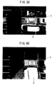
- FIG. 38 illustrates an example of placement of eight cameras (cameras 0 to 8 ) on a vehicle 1 (hereinafter, a vehicle on which a camera is mounted is referred to as a user's vehicle) and examples of images taken with the cameras 0 to 8 (camera images).
- FIG. 39 is an image of the surroundings of the vehicle shown in FIG. 38.
- FIG. 40 is an image obtained by performing road surface projection using the eight camera images shown in FIG. 38 . Note that since it is hardly possible to obtain an image of the user's vehicle 1 itself from the camera images shown in FIG. 38 , an illustration of the user's vehicle 1 is fitted into the image shown in FIG. 40 for convenience.
- the image of an object having a height component distorts greatly in the direction farther from the user's vehicle 1 , and this makes the user consider that something exists in an area of the road in which actually nothing exists.
- This mismatch between the actual surroundings and the synthesized image may possibly cause misunderstanding by the user and thus may impair the user's safety driving.
- a method using a distance-measuring sensor such as a laser radar may be employed. That is, for a three-dimensional object having a height component such neighboring vehicles, distance data may be previously obtained with a distance-measuring sensor, and perspective transform is performed using a three-dimensional profile determined from the obtained distance data as the projection plane.
- this method By adopting this method, no image distortion is generated unlike the case of the road surface projection. However, this method still has a problem that a region concealed behind an object located closer to a camera (occlusion region) is formed.
- FIG. 38 it is known from the images taken with the cameras 1 and 2 that a car is at a stop on the right side of the user's vehicle 1 .
- no image of the right part of the car is taken with any of the cameras because the right part is concealed by the left part of the car.
- the right part therefore corresponds to an image missing region of a surroundings image of the user's vehicle in which no image data has been taken with the cameras. Therefore, even if all distance data is obtained for the surroundings, only the left part of the car of which camera images are available is shown in the resultant synthesized image because image synthesis fails for the right part of the car corresponding to the image missing region.
- cameras are generally mounted on a vehicle, and the number of cameras is limited due to restriction in cost and the like. Therefore, the above problem occurs for almost all three-dimensional objects in the surroundings of the vehicle.
- FIG. 41 is a synthesized image obtained when distance data on the neighboring objects is all known. As is found from FIG. 41 , while distance data on the vehicles existing around the user's vehicle 1 is all known for the sides thereof closer to the user's vehicle, the opposite sides of the vehicles farther from the user's vehicle belong to image missing regions. Therefore, for each vehicle, an image can be generated only for the user's vehicle side.
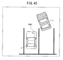
- FIG. 42 is an illustration of a situation in which a vehicle 3 exists in a left-hand rear position with respect to the user's vehicle 1 , viewed from above. Referring to FIG. 42 , for safe parking operation, it is important to accurately recognize the position of an area AR1 of the vehicle 3 on the side closer to the user's vehicle 1 .
- FIG. 43 is an example of display of the situation shown in FIG. 42 , in which the vehicle 3 is represented by a picture 3A smaller than the actual size of the vehicle.
- areas AR2 to AR4 are not shown for the user although actually these areas are part of the vehicle 3 .
- the area AR2 relates to a border of the vehicle 3 closer to the user's vehicle, which is important during parking of the user's vehicle. This display is therefore inappropriate.
- FIG. 44 is an example of display of the situation shown in FIG. 42 , in which the vehicle 3 is represented by a picture 3B larger than the actual size of the vehicle.
- areas AR5 to AR7 are shown as if they are part of the vehicle 3 for the user although actually the vehicle 3 does not occupy these areas.
- the areas AR5 and AR7 relate to borders of the vehicle 3 closer to the user's vehicle, which is important during parking of the user's vehicle. This display is therefore inappropriate.
- An object of the present invention is providing a vehicle surroundings display device capable of allowing the user to accurately recognize the position of a neighboring object that is important in driving operation and eliminating unnaturalness the user may feel due to failure of display of an image in an occlusion region.
- Another object of the present invention is providing an image providing system capable of eliminating unnaturalness the user may feel for a region of a provided image in which image data from a camera is not available due to existence of an object.
- the occlusion region as used herein refers to a region that is not viewed via any camera placed on the user's vehicle. During driving operation such as parking, it is important to display the position of the border of a neighboring object on the user's vehicle side. As for the occlusion region, it is considered that an accurate image in an accurate position is not necessarily required, but display to a degree of accuracy that the user does not feel unnaturalness is sufficient. To state specifically, in the example shown in FIG. 42, only the area AR1 of the vehicle 3 is visible from the user's vehicle. The other area of the vehicle 3 is viewed neither via cameras nor directly by the eyes. However, this does not especially impair the driving operation.
- a non-concealed region must be displayed in an accurate position.
- the image displayed is preferably not so different from the actual object.
- the image in the “non-concealed region”, the image is displayed in an accurate position, while in the "occlusion region", an image to a degree of accuracy that the user does not feel unnaturalness is sufficient.
- the vehicle surroundings display device of the present invention includes: a camera for taking an image of the surroundings of a vehicle; obstacle detection means for detecting an obstacle in the surroundings of the vehicle; an image processor for generating a surroundings image representing the situation around the vehicle from the image taken with the camera; and image missing region detection means for detecting an image missing region in the surroundings image when the obstacle is detected by the obstacle detection means, the image missing region failing to obtain image data from the camera due to existence of the obstacle, wherein the image processor fills at least part of the image missing region with substitute image data when the image missing region is detected.
- an image missing region failing to obtain image data from the camera due to existence of the obstacle and the like is detected by the image missing region detection means.
- the image processor fills at least part of the image missing region with substitute image data.
- unnaturalness of the image missing region corresponding to the "occlusion region” described above is reduced by the filling with substitute image data, and camera image data is used for the portion other than the image missing region corresponding to the "non-concealed region". Therefore, the user does not feel unnaturalness for the surroundings image so much and can recognize the position of the obstacle in the surroundings of the vehicle accurately.
- safe driving operation is possible more reliably and comfortably than in the conventional case.
- the image missing region detection means includes object position detection means for detecting the position of a border of the obstacle on the vehicle side, and determines the image missing region using the detected border position.
- the image processor preferably uses a border image including at least the border portion of the obstacle on the vehicle side for generation of the substitute image data.
- the border image including the border portion of the obstacle on the user's vehicle side is used for generation of substitute image data for filling of the image missing region. It is therefore possible to present to the user an image indicating the accurate border position of the obstacle on the user's vehicle side, which is important for driving operation.
- the image processor places the border image on the surroundings image so as to align with the border position detected by the obstacle position detection means, presumes a region occupied by the obstacle in the surroundings image by aligning with the border position, and generates the substitute image data by pixel interpolation using pixel data of the border image for a portion of the presumed obstacle region other than the border image.
- the border image is placed in the accurate border position, and an image of the portion of the obstacle other than the border image is generated by pixel interpolation using pixel data of the border image. This enables generation of a surroundings image in which the border position of the obstacle on the user's vehicle side, important for the user, is accurate and for which the user does not feel unnatural.
- the image processor assumes a symmetry axis of the obstacle in the surroundings image, inverts the border image with respect to the symmetry axis to provide an inverted border image, and generates an image between the border image and the inverted border image in the obstacle region by the pixel interpolation using pixel data of the border image.
- This enables generation of a synthesized image of an occlusion region free of unnaturalness by use of axisymmetry of the object such as a vehicle.
- the vehicle surroundings display device of the invention described above may further includes an obstacle image database for storing image data of objects as candidates of obstacles, wherein the image processor determines the type of the detected obstacle, reads image data of the determined type of obstacle from the obstacle image database, places the read image data on the surroundings image to align with the border position detected by the obstacle position detection means as the substitute image data.
- an obstacle image database for storing image data of objects as candidates of obstacles, wherein the image processor determines the type of the detected obstacle, reads image data of the determined type of obstacle from the obstacle image database, places the read image data on the surroundings image to align with the border position detected by the obstacle position detection means as the substitute image data.
- image data of objects as candidates of obstacles are held as a database, and image data of a determined type of obstacle is placed to align with the border position as substitute image data. Therefore, an image similar to an actual obstacle can be presented in an accurate position.
- the image processor preferably determines the type of the obstacle based on the image from the camera.
- the obstacle position detection means detects a contact position of a tire of the vehicle with the road surface in the image from the camera as the border position.
- the existence of a tire can be used to detect the accurate border position.
- the obstacle position detection means detects a line of a plane including a number plate of the vehicle in contact with the road surface in the image from the camera as the border position.
- the image processor generates the surroundings image by performing virtual viewpoint transform based on the image from the camera.
- the image providing system of the present invention includes: a camera for taking an image; detection means for detecting an object in an image-provided range; an image processor for generating a provided image showing the situation in the image-provided range from the image taken with the camera; and image missing region detection means for detecting an image missing region in the provided image when an object is detected by the detection means, the image missing region failing to obtain image data from the camera due to existence of the object, wherein the image processor fills at least part of the image missing region with substitute image data when the image missing region is detected.
- an image missing region failing to obtain image data from the camera due to existence of the object is detected by the image missing region detection means.
- the image processor fills at least part of the image missing region with substitute image data.
- unnaturalness of the image missing region is reduced by the filling with substitute image data, and camera image data is used for the portion other than the image missing region. Therefore, the user does not feel unnaturalness for the provided image so much and can recognize the situation in the image-provided range accurately.
- the camera takes an image of the surroundings of a vehicle.
- the camera takes an image of the inside or surroundings of a building.
- FIGS. 45A and 45B show a situation in which a vehicle 2 is at a stop in the rear of a user's vehicle 1 , viewed from a side and from above, respectively.
- a camera 11 is mounted on the user's vehicle 1 for taking images in the rear. Using images taken with the camera 11 , a synthesized image viewed via a virtual camera VC is generated.
- the line RS denotes a road surface.
- an occlusion region concealed by the front portion of the vehicle 2 is generated.
- images of portions of the vehicle 2 corresponding to the occlusion region must be displayed.
- no image data is provided from the camera 11 for these portions, which therefore constitute an image missing region.
- a region for which no image data is available from any camera due to existence of an object or an obstacle, such as the vehicle 2 constitutes an image missing region in an image to be displayed.
- the image missing region also includes a portion that is originally outside the field of view of the camera, for which no image data is available naturally.
- FIG. 1 conceptually shows a basic configuration of a vehicle surroundings display device of Embodiment 1 of the present invention.
- the vehicle surroundings display device of FIG. 1 includes, as a basic configuration: a camera 11 for taking images of the surroundings of a vehicle; an obstacle detection means 12 for detecting an obstacle in the surroundings of the vehicle; an obstacle position detection means 13 for detecting the position of the border of the obstacle on the vehicle side; and an image processor 14 receiving the images taken with the camera 11 (camera images) for generating an image showing the situation around the vehicle from the received camera images.
- the camera 11 is typically mounted on the vehicle for taking images of the situation around the vehicle. Cameras placed somewhere in infrastructures such as roads, signals and buildings may also be used. Otherwise, images taken with cameras mounted on other vehicles around the user's vehicle, if any, may be received and used together with the images taken with the camera 11 or independently.
- the obstacle detection means 12 detects an obstacle in the surroundings of the vehicle, by any of the following methods, for example.
- the color of the road surface is extracted from images taken with the camera 11 .
- a region having a height component is extracted by a technique of stereo vision or the like utilizing parallax obtained from a plurality of images, to detect this region as an obstacle region.
- various active sensings for obstacle detection using laser, ultrasonic, ultraviolet, extremely high frequency (EHF) and the like may be used.
- Detection of an obstacle region by extracting the color of the road surface will be described. Assuming that a camera faces in a downwardly slanted direction with respect to the horizontal direction, the road surface presumably occupies the broadest region of a camera image. It is therefore possible to determine a typical color of the road surface by preparing a histogram of colors of the image and extracting the color having the highest frequency.
- the color of a paved road surface is gray that is the color of asphalt, while the color of an unpaved road surface is brown. Therefore, the region other than the road surface, that is, an obstacle region can be determined by finding a region having a color greatly different from the extracted typical color.
- the obstacle position detection means 13 detects the position of the border of the obstacle region detected by the obstacle detection means 12 on the user's vehicle side, that is, the position of the boundary of the obstacle closest to the user's vehicle.
- This detection can be realized by performing raster scanning with an active sensing in the direction horizontal to the side face of the user's vehicle, or by a method using a range finder as follows. First, scanning is performed with a range finder in the direction vertical to the road surface. A position closest to the user's vehicle is determined from distances measured by the vertical scanning. The vertical scanning is repeated for the detected obstacle over a horizontal fan-shaped area, and the positions closest to the user's vehicle determined by the scans are connected as a line in the horizontal direction. This line is determined as the border of the obstacle on the user's vehicle side.
- FIG. 2 is a view showing a situation in which a vehicle 2 is at a stop on one side of a user's vehicle 1.
- a side profile E1 as the border of the vehicle 2 on the side closer to the user's vehicle 1 can be determined by scanning with an active sensing as the obstacle position detection means 13 .
- the resultant surroundings image presented to the user inevitably includes an image missing region due to existence of an occlusion region.
- the resultant image is considerably unnatural as a whole.
- the obstacle position detection means 13 detects the position of the border of the obstacle on the user's vehicle side, and the image processor 14 determines an image missing region using the detected border position and fills at least part of the image missing region with substitute image data, to generate a surroundings image for which the user does not feel unnaturalness.
- the obstacle position detection means 13 and the means for determining the image missing region constitute an image missing region detection means.
- road surface projection or perspective projection transform is performed for the portion of an image other than an obstacle region detected by the obstacle detection means 12 to generate a vehicle surroundings image.
- an image of the obstacle region detected by the obstacle detection means 12 is processed, re-synthesizing to eliminate unnaturalness, and the resultant image is placed on the vehicle surroundings image so that the border position detected by the obstacle position detection means 13 is located accurately, to thereby complete the vehicle surroundings image.
- the resultant vehicle surroundings image is displayed on a display device such as a liquid crystal display and a head-mounted display to be presented to the user.
- An important point in the above processing is to position the border of the obstacle on the user's vehicle side accurately when the image of the obstacle region is placed on the vehicle surroundings image. This is because, if the obstacle is displayed in the vehicle surroundings image in a position farther than the actual position with respect to the user's vehicle, the user's vehicle may possibly come into contact with the obstacle.
- the obstacle position detection means 13 therefore plays an importance role to avoid this problem.
- the image processor 14 fills in the obstacle region with a background color such as black, not displaying an image.
- the user is presented with a vehicle surroundings image including only the road surface region displayed.
- the border of the obstacle on the user's vehicle side is displayed in the image accurately at the position obtained by the obstacle position detection means 13. Therefore, the possibility of contact of the user's vehicle with the obstacle is avoided.
- the border of the obstacle on the side opposite to the user's vehicle side is in an occlusion region. However, since this region is not so important for driving operation as described above, filling-in of this region with a background color will not cause a problem.
- FIG. 3 shows an example of an image obtained by performing the processing described above for the synthesized image of FIG. 41, in which obstacle regions OB1 to OB5 in the surroundings of the user's vehicle 1 are filled in with black.
- the user is urged to confirm the regions directly by the eyes, and this prevents occurrence of a problem caused by mismatch between a distorted synthesized image and the actual surroundings.
- a range a little wider than the actual obstacle region may be filled in considering a possible error in detection.
- the region may be more degraded in precision or masked with the degree of precision of detection that the region is outside the road surface, to thereby prevent this region from attracting the attention of the user.
- FIG. 3 although the image of the user's vehicle 1 is hardly obtained from the camera images shown in FIG. 38 , the position of the user's vehicle 1 is very important to recognize the positional relationship between the user's vehicle and the neighboring obstacles. Therefore, an illustration of the user's vehicle 1 is pasted to the position of the user's vehicle 1 . Alternatively, an image of the actual user's vehicle 1 may be stored in advance and pasted.
- the size of an obstacle may be detected by the obstacle detection means 12 , and a simple rectangle or a box-like three-dimensional object corresponding to this size may be superimposed on the obstacle region. This may call the user's attention to this region and urge the user to confirm the region directly by the eyes.
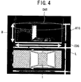
- FIG. 4 is an enlarged view of an area near the user's vehicle 1 in FIG. 41 .
- the length L of a border EDG of a neighboring obstacle on the user's vehicle side shown in FIG. 4 can be determined by the obstacle detection means 12 . Therefore, a rectangle RTG having a side of length L is generated and superimposed on the obstacle region so that the side aligns with the border EDG .
- the length W of the other side of the rectangle RTG vertical to the L-long side may be arbitrarily determined. In the illustrated example, the length W is simply a half of the length L .
- a region OAR of the obstacle on the side opposite to the user's vehicle side is not important so much for the user, and thus the effect is considered small if a displacement occurs between the synthesized image and the actual obstacle in this region.
- the length W can also be determined from the tilt of the side profile of the obstacle obtained by the obstacle position detection means 13 . This is based on the assumption that the length W is longer with respect to the length L as the tilt of the side profile of the obstacle is slower with respect to the length L .
- FIG. 5 shows an example of an image obtained by performing the processing described above for the synthesized image of FIG. 41, in which rectangles RTG1 and RTG2 are generated for the obstacle regions.
- the color of the rectangles may be a typical color of obstacles, or may be a color attracting the user's attention.
- three-dimensional objects such as rectangular parallelepipeds may be displayed. Otherwise, if the border EDG is a curve, an oval object having a line extending along this curve may be superimposed on the obstacle region. Moreover, an illustration and a word may be superimposed on the region for attracting attention.
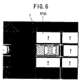
- FIG. 6 shows an example of an image in which each obstacle region is represented by a rectangle RTG1 and a code is superimposed on the region.
- the code "! is superimposed to call the user's attention.
- the border of the rectangle on the user's vehicle side is displayed accurately in the position of the neighboring obstacle obtained by the obstacle position detection means 13. This prevents the user's vehicle from coming into contact with the neighboring obstacle unlike the second prior art in which an illustration is simply pasted.
- Another code, a word or an illustration helpful in calling the user's attention may be used in place of "!.
- the vehicle surroundings display device of Embodiment 2 of the present invention has a basic configuration as shown in FIG. 1 , as in Embodiment 1, that is, has the camera 11 , the obstacle detection means 12 , the obstacle position detection means 13 and the image processor 14 as main components.
- Embodiment 1 is different from Embodiment 1 in the function of the image processor 14 .
- the image processor 14 uses a border image including at least a border portion of the obstacle on the user's vehicle side detected by the obstacle position detection means 13 to generate substitute image data for filling an image missing region, and displays the substitute image data in an accurate position so that the user does not feel unnaturalness for the resultant image.
- obstacles in the surroundings of a vehicle are roughly axisymmetric as cars are.
- the axisymmetry is used for generation of an image of an obstacle region as substitute image data.
- FIG. 7A is a diagrammatic view of an image of the user's vehicle 1 and a vehicle 2 existing on the right of the user's vehicle 1 , viewed from above the user's vehicle 1 .
- FIG. 7B is a diagrammatic view showing an image 2A of the vehicle 2 taken with the camera 11 mounted on the user's vehicle 1 , together with the positional relationship between the user's vehicle 1 and the vehicle 2 , in the situation shown in FIG. 7A .
- FIG. 8 is a synthesized image generated by the road surface projection described in Japanese Patent Application No. 2000-613188 in the situation shown in FIG. 7A.
- FIG. 8 shows a border EDG of the vehicle 2 on the user's vehicle side determined by the obstacle position detection means 13 .
- the image of the vehicle 2 having a height component is distorted and the projected position greatly differs from the actual position, as shown in FIG. 8 . Therefore, a problem in this embodiment is how an image of the vehicle 2 should be superposed so as to align with the border EDG .
- FIG. 9 is a flowchart of operation of the image processor 14 in the first example of this embodiment.
- step S11 the position of the border of an obstacle on the user's vehicle side and the length L of the border are determined by the obstacle detection means 12 and the obstacle position detection means 13 .
- the border of the obstacle on the user's vehicle side is a straight line, that is, the obstacle or the vehicle existing on a side of the user's vehicle is viewed right from the side.
- step S12 the length W of the obstacle in the depth direction (orthogonal to the border of the obstacle) is arbitrarily determined.
- the length W is assumed to be a half of the length L .
- the length orthogonal to the border is not so important for the user and thus the effect is considered small if a displacement occurs between the actual obstacle and the synthesized image.
- step S13 a side profile ( E1 in FIG. 2 , for example) of the detected obstacle is determined by the obstacle position detection means 13 , to be used as a projection plane for the neighboring obstacle.
- step S14 an obstacle image taken with the camera 11 is projected on the projection plane, and then viewpoint transform is performed to obtain a projected image of part of the obstacle, that is, a border image.
- the obstacle image in the camera image 2A taken with the camera 11 is subjected to perspective projection transform using the obstacle side profile E1 obtained by the obstacle position detection means 13 as the projection plane.
- the viewpoint is then transformed so that the obstacle is viewed from above, to thereby obtain a border image EDI of the obstacle.
- the obstacle border image EDI lacks in information on an occlusion region of the obstacle including the roof, the front, the back and the side opposite to the user's vehicle side. Therefore, as is shown in FIG. 10, the obstacle border image EDI, including only part of the obstacle, is a thin image with one side face standing like a wall.
- FIG. 11A diagrammatically shows the border image EDI placed in an obstacle region of a surroundings image.
- a virtual symmetry axis AX is assumed along a position of a half of the width W so that the width of the obstacle is equal to the width W determined in step S12.
- An inverted border image OEDI obtained by inverting the border image EDI with respect to the virtual symmetry axis AX is placed to align with the border position on the side opposite to the user's vehicle side (position apart from the position of the border image EDI by the width W ).
- step S16 the blank region VAR is filled by interpolating pixels of the border image EDI and the inverted border image OEDI, to complete a synthesized image of the neighboring obstacle.
- FIG. 12 is an enlarged view of FIG. 11B, in which the x-axis is put in the direction along the border of the obstacle on the user's vehicle side, and the y-axis is put in the direction orthogonal to the x-axis.
- the x coordinates of the leftmost and rightmost ends of the blank region VAR are X0 and X1, respectively
- the y coordinates of the positions of the border image EDI and the inverted border image OEDI closest to the blank region VAR are Y1 and Y2, respectively.
- G(x, y) (X0 ⁇ x ⁇ X1, Y1 ⁇ y ⁇ Y2) in the blank region VAR is then determined by expression (1) below.
- G(x,y) (Y2-y)G(x,Y1)+(y-Y1)G(x,Y2) Y2-Y1
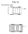
- FIG. 13 is a diagrammatic view of the surroundings image generated in the manner described above, in which 2B denotes a synthesized image of the vehicle as the neighboring obstacle. Note that the texture, average brightness, typical color and the like of the border image EDI may also be used for interpolation of pixels in the blank region VAR.
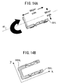
- the border of an obstacle on the user's vehicle side obtained may be of an L shape, not a straight line. Processing in this case will be described in detail with reference to FIGS. 14A and 14B .
- an L-shaped border image EDIL is obtained.
- a symmetry axis AX extending through the center of the minor side and in parallel with the major side is assumed.
- the border image EDIL is rotated by 180 degrees with respect to the symmetry axis AX to obtain an inverted border image OEDIL as shown in FIG. 14B.
- the border image EDIL takes precedence over the inverted border image OEDIL in the overlap region of the border images EDIL and OEDIL. This is because the border image EDIL reflects the actual surroundings more correctly.
- the symmetry axis AX may be determined based on the length of the major side as in the example described above.
- the x-axis and the y-axis are put along the major side and the minor side, respectively, as in the example described above, to perform interpolation of pixels as described above.
- the x-axis and the y-axis may be put along the minor side and the major side, respectively.
- the y-axis may be put along a side closer to the line of sight of the camera, or the x-axis and the y-axis may be switched appropriately depending on camera images.
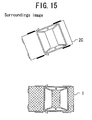
- FIG. 15 is a diagrammatic view of the surroundings image generated in the manner described above, in which 2C denotes a synthesized image of the vehicle 2 as the neighboring obstacle.
- the curved border When the border of an object obtained is a curve, the curved border may be subjected to linear approximation by the method of least squares and the like.
- the x-axis is put along the resultant straight line, and a virtual symmetry axis is assumed along a line obtained by parallel displacement of the x-axis, to perform processing as described above.
- the curved border may be subjected to L-shape approximation, to perform similar processing by putting the x-axis and the y-axis along the two sides of the L shape.
- FIG. 16 is an image obtained by performing the processing in this example for the synthesized image shown in FIG. 41.
- an obstacle image OIM1 generated using the inverted border image and interpolation is superposed on each obstacle region.
- an inverted border image was used on the assumption that the neighboring obstacle was roughly axisymmetric. It is also possible to generate an obstacle image using only interpolation of pixels without use of an inverted border image. That is, an obstacle image as substitute image data filling an image missing region may be obtained from the border image of the obstacle on the user's vehicle side simply by performing only interpolation of pixels. This method is effective when use of axisymmetry is not available, such as when a neighboring vehicle is in the front or rear of the user's vehicle and images of only the front or rear portion of the neighboring vehicle are taken with the camera.
- FIG. 17 is a flowchart of operation of the image processor 14 in the second example of this embodiment. Steps S21 to S24 are the same as steps S11 to S14 of the flow in the first example shown in FIG. 9 . Interpolation of pixels in steps S25 in this example will be described with reference to the relevant drawings.
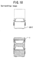
- FIG. 18 is a diagrammatic view of a synthesized image of a situation in which a neighboring vehicle exists in the rear of the user's vehicle 1.
- a border image EDI2 of the neighboring vehicle is placed in the rear of the user's vehicle 1 .
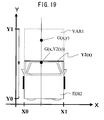
- FIG. 19 is a partial enlarged view of FIG. 18, in which the x-axis is put in the lateral direction and the y-axis is put in the depth direction with respect to the position of the user's vehicle in the synthesized image.
- the length W in the depth direction of the neighboring obstacle can be arbitrarily determined. Therefore, the obstacle region (x, y) can be presumed as X0 ⁇ x ⁇ X1 and Y1 ⁇ y ⁇ Y2.
- VAR1 is an image missing region of the obstacle region for which no synthesized image has been determined.
- a pixel G(x, y) (X0 ⁇ x ⁇ X1, Y2(x) ⁇ y ⁇ Y1) in the region VAR1 is then determined by expression (1) above as G(x, Y2(x)).
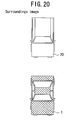
- FIG. 20 is a diagrammatic view of a surroundings image generated in the manner described above, in which 2D denotes a synthesized image of the vehicle 2 as the neighboring obstacle.
- FIG. 21 is an image obtained by performing the processing in this example for the synthesized image shown in FIG. 41.
- an obstacle image OIM2 generated using the border image and interpolation is placed on each obstacle region.
- the image processor 14 may have a function of switching the processing using a border image, an inverted border image and interpolation described in the first example and the processing using interpolation for a border image described in the second example, and execute either of these types of processing by switching for each obstacle.
- the processing may be switched by determining the orientation of the vehicle. That is, the processing in the first example is performed when the neighboring vehicle is on one side of the user's vehicle, and the processing in the second example is performed when it is in the front or rear of the user's vehicle.
- the orientation of a vehicle can be determined by detecting a number plate and a tire in the obstacle region detected by the obstacle detection means 12 .
- a number plate can be detected from a camera image by a technique using the fact that number plates have the same size or by a technique described in Japanese Laid-Open Patent Publication No. 10-302074, for example. In the latter technique, small regions are cut from an image and input into a neural network after being subjected to edge emphasizing and size scaling. A small region that has earned the maximum output is determined as the number plate position.
- a tire can be detected by any of known techniques using template matching and Hough transform.
- the neighboring vehicle is in the front or rear of the user's vehicle when a number plate is detected but no tire is detected, on one side of the user's vehicle when a tire is detected but no number plate is detected, and located at a certain angle with respect to the user's vehicle when both a number plate and a tire are detected. Also, when both a number plate and a tire are detected, the processing in the second example is possible by setting a straight line including the tire in the border position as the x-axis and a straight line including the number plate in the border position as the y-axis.
- FIG. 22 is a synthesized image obtained by switching the interpolation processing.
- the synthesized image in FIG. 22 includes an obstacle image OIMA generated by the technique using an inverted border image in the first example and an obstacle image OIMB generated by the technique using interpolation for a border image in the second example.
- a vehicle having an axisymmetric shape was used as an example of an obstacle.
- This embodiment is also effective for non-axisymmetric obstacles. The reason is that in the processing of this embodiment, a border image of an obstacle is placed in the accurate position without fail. Therefore, although a correct image of an image missing region of a non-axisymmetric obstacle is not always presented, the border position of the obstacle on the user's vehicle side, which is important during driving, is presented accurately without fail.
- FIG. 23 shows a basic configuration of a vehicle surroundings display device of Embodiment 3 of the present invention.
- the vehicle surroundings display device of this embodiment includes an obstacle image database 31 for storing image data of objects as potential obstacles, in addition to the camera 11 , the obstacle detection means 12 , the obstacle position detection means 13 and an image processor 14A .
- the operation of the image processor 14A is different from the image processor 14 in Embodiments 1 and 2. That is, the image processor 14A determines the type of an obstacle detected by the obstacle detection means 12 , reads image data for the determined type of obstacle from the obstacle image database 31 , and places the read image data on a surroundings image to align with the border position detected by the obstacle position detection means 13 as substitute image data filling an image missing region of the surroundings image.
- the obstacle image database 31 includes data on obstacles, such as the aspect ratio, the side profile and the model when vehicles are taken as an example.
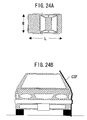
- FIGS. 24A and 24B illustrate a vehicle as is viewed from above and from the front, respectively.
- the "aspect ratio of a vehicle” is a ratio of the length L to the width W in FIG. 24A .
- the distance between the right and left tires of a vehicle is roughly equal to the width W of the vehicle. Therefore, by measuring this distance, the width W of a vehicle can be obtained.
- the "side profile of a vehicle” is a three-dimensional profile CSF of a vehicle in FIG. 24B , which can be used as a border image.
- FIG. 25 shows an example of model data, in which the model data includes model identifying data used for model identification, color data showing available colors for respective models, and display data used for image display.
- model identifying data refers to a binary-coded image in which, when edges and feature-points of a camera image are used for model identification, for example, a pixel including an edge or a feature-point is set at "1" and a pixel including no edge or feature-point is set at "0".
- the size of such binary-coded images is normalized to a fixed value.
- color data all colors of respective models available in the market may be stored, for use in model identification using brightness and positioning of an obstacle image to be described later.
- color data is represented by 256-level gray scale for each of RGB. Specifically, red is represented by (255, 0, 0), green by (0, 255, 0) and blue by (0, 0, 255).
- the "display data" is used for placement of an obstacle image to be described later.
- the model identifying data and display data are desirably held so that they are transformable to data from any viewpoint. This can be realized by storing three-dimensional profile data of vehicles.
- the image processor 14A roughly determines the type of an obstacle detected by the obstacle detection means 12 , such as whether the obstacle is a car or a motorcycle, and based on the determination result, the model is identified if the obstacle is a car.
- FIG. 26 is a flowchart of operation of the image processor 14A in this embodiment.
- step S31 rough determination of the type of the obstacle, such as whether or not the obstacle is a car (step S32 ) and whether or not the obstacle is a motorcycle (step S33 ), is performed. If the obstacle is determined to be a car in step S32, the model of the car is identified in step S34. If the obstacle is determined not to be a car (NO in step S32 ), whether or not the obstacle is a motorcycle is determined. If the obstacle is determined to be a motorcycle in step S33 , the model of the motorcycle is identified in step S35 . If the obstacle is determined not to be a motorcycle (NO in step S33 ), the process proceeds to another determination step on whether or not the obstacle is a person, for example.
- the obstacle determination steps S32 and S33 can be realized using a neural network and the like.
- a neural network can output a pattern among previously-learnt patterns that is most approximate to an input. Therefore, by making a neural network learn a large amount of data on various cars as "car patterns” and a large amount of data on various motorcycles as “motorcycle patterns", it is possible to determine whether or not the detected obstacle data indicates a car or a motorcycle. It is naturally possible to use the model identifying data and the display data stored in the obstacle image database 31 as the learning patterns. That is, the determination steps S32 and S33 may be united as a single step.
- image data of the identified model is read from the obstacle image database 31, and the read image data is placed on the surroundings image to align with the border position detected by the obstacle position detection means 13 (step S36 ).
- FIG. 27 is a flowchart of model identification in this embodiment.
- step S401 two variables M0 and M2 are initialized at 0.
- step S402 a typical color, edges and feature-points are extracted from an obstacle region detected by the obstacle detection means 12.
- the typical color can be extracted by obtaining a histogram for all pixels in the obstacle region.
- Edges and feature-points can be extracted using convolution with a Sobel operator. A pixel from which an edge or a feature-point is detected is set at "1" and a pixel from which no edge or feature-point is detected is set at "0", to generate an edge/feature-point binary-coded image.
- step S403 one model is selected from model data stored in the obstacle image database 31 , and the model identifying data and the color data for the model are retrieved. Using the retrieved data, whether or not the model selected in step S403 matches with the detected obstacle is determined in step S404 and the subsequent steps.
- step S404 whether or not a color close to the typical color of the detected obstacle is included in the color data of the model is examined.
- the closeness of the color can be determined by measuring the distance between the typical color and the color data of the model in the RGB three-dimensional space. If a color sufficiently close to the typical color exists in the color data, the process proceeds to step S405 , for comparison of the edge/feature-point. If no color sufficiently close to the typical color exists, the detected obstacle is determined different from the model selected in step S403 , and the process proceeds to step S408 for comparison with data of another model (step S403 ).
- step S405 the degree of matching M1 is calculated between the edge/feature-point of the obstacle and the model identifying data for the model selected in step S403 . This can be calculated by comparing the previously-generated edge/feature-point binary-coded image of the obstacle with the edge/feature-point binary-coded image of the selected model.
- the numerator of the above expression represents the total number of edges/feature-points matching in position between the obstacle and the model data
- the denominator represents the total number of edges/feature-points existing in the obstacle and the model data. That is, as the value of M1 is greater, the two edge/feature-point binary-coded images are more similar to each other, and as the value of M1 is smaller, the two images are more different.
- step S406 whether or not the degree of matching M1 is greater than the value of the variable M0 is determined. If M1 is smaller, the obstacle is determined different from the selected model, and the process proceeds to step S408 for comparison with data of another model ( S403 ).
- the value of M0 is set at M1, and the value of M2 is set at the model number of the selected model to be held as a model candidate.
- the process then proceeds to step S408 for comparison with data of another model ( S403 ).
- the variable M0 now holds the value of the degree of matching of the most probable model candidate used for comparison so far. In this way, by comparing the detected obstacle with all the models stored in the obstacle image database 31 , a model exhibiting the highest similarity to the obstacle can be identified.
- step S409 whether or not the model candidate is adequately similar to the obstacle is determined. This can be made by checking whether or not the degree of matching M0 of the model indicated by M2 determined as having the highest similarity is greater than a predetermined value. If M0 is greater than the predetermined value, it is decided that the obstacle is adequately similar to the model M2, and the process is terminated with decision that "the model of the detected obstacle is M2" ( S410 ). If M0 is smaller than the predetermined value, it is decided that the obstacle is not adequately similar to the model M2, and the process is terminated with decision that "the model of the detected obstacle is not identifiable" ( S411 ).
- the calculation of the degree of matching with various model data may be made in parallel, not sequentially as described above, to shorten the processing time.
- Model identification of a motorcycle can also be performed in a manner similar to that shown in FIG. 27 using motorcycle model data stored in the obstacle image database 31.
- the type determination and model identification of an obstacle can be performed by one operation without the rough type determination, by using all of the car model data and the motorcycle model data stored in the obstacle image database 31 as the obstacle data.
- car model data data of roughly classified models such as a passenger car, a van, a light truck and a truck may be used.
- the obstacle image database 31 preferably includes a means for updating the model data.
- the vehicle surroundings display device of this embodiment may periodically access a database including constantly updated model data to update the model data in the obstacle image database 31.
- the model data may be updated via a memory medium such as a CD and a DVD, or by accessing another vehicle surroundings display device having updated model data via inter-vehicle communications to receive the model data.
- An obstacle identification method using images is described in O. Hasegawa et al., "On-line identification of an object in a general road image", Seventh Symposium on Sensing via Image Information Collected Papers, pp. 221-226 (Literature 2).
- Another example of the method for identifying a vehicle model using images is described in Japanese Laid-Open Patent Publication 2001-101405. In this method, a large amount of data on various models is collected and grouped, and used as learning images to realize model identification.
- model information may be obtained from the number plate of a neighboring vehicle recognized as an obstacle.
- step S36 in FIG. 27 data representing the obstacle detected by the obstacle detection means 12 is placed on the surroundings image to present the obstacle in an accurate position so that the user does not feel unnaturalness for the resultant image.
- FIG. 28 is a flowchart of the placement of an obstacle image in step S36.
- the obstacle has been determined as a car and the model of the car has been identified in step S34.
- Image data for the identified car model is read from the obstacle image database 31 to determine a neighboring obstacle image to be presented to the user (step S51 ).
- the image obtained in this step has been viewpoint-transformed so that the image fits to the border position detected by the obstacle position detection means 13.
- the neighboring obstacle image must be an image viewed from above as shown in FIG. 7A .
- An illustration or image data of an actual vehicle may be used as the neighboring obstacle image.
- the read neighboring obstacle image is placed on the surroundings image to align with the border position of the obstacle on the user's vehicle side detected by the obstacle position detection means 13 (step S52 ).
- the border position of the obstacle on the user's vehicle side may also be detected by determining the contact position of a tire of the vehicle with the road surface from the image as described below.
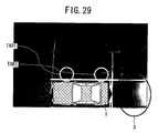
- FIG. 29 is a synthesized image generated from the image shown in FIG. 7B by road surface projection described in Japanese Patent Application No. 2000-613188.
- road surface projection is performed on the assumption that all objects in an image are in the plane of the road surface. Therefore, an image of a neighboring vehicle having a height component is distorted as shown in FIG. 29, and the projected position is greatly different from the actual position.
- tire regions TAR1 and TAR2 that are in contact with the road surface, which have no height component, are projected in accurate positions.
- a synthesized image accurate in relative positions can be generated by using the contact positions of the tires with the road surface as the reference. Determination of the contact positions of tires with the road surface will be described with reference to the relevant drawings.
- FIG. 30 is an image of a region detected as an obstacle by the obstacle detection means 12.
- the obstacle position detection means 13 extracts an edge from this image using a Sobel operator described above, and from the result of the edge extraction, finds out an edge portion matching with an arc pattern CP1 shown in FIG. 31 simulating the lower portion of a tire.
- This processing can also be performed using template matching, Hough transform and the like.
- FIG. 32 shows the result of the edge extraction from the image of FIG. 30 .
- matching regions MAR1, MAR2 and the like are obtained as edge portions matching with the arc pattern CP1.
- tires are generally placed in the front and rear in pairs. Therefore, the two matching regions placed side by side are determined as the contact positions of tires with the road surface. That is, in the example in FIG. 32, the matching regions MAR1 and MAR2 are determined as the contact positions of the tires with the road surface.
- the fact that tires are always in contact with a non-obstacle region may be used as a condition for detection.
- the image processor 14A superposes the image data read from the obstacle image database 31 on the contact positions MAR1 and MAR2 of the tires with the road surface, to generate a neighboring vehicle synthesized image.
- the read image data is rotated so that the front and rear tires are located on the straight line connecting the two contact positions MAR1 and MAR2.
- the rotated image data is enlarged or contracted so that the positions of the two front and rear tires fit with the contact positions MAR1 and MAR2, to generate a synthesized image.
- FIG. 33 shows the thus-generated synthesized image.
- the border position detection method using tires described above is not adoptable.
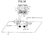
- the number plate for example, may be used for border position detection. This processing using a number plate will be described with reference to FIG. 34.
- the reference numeral 41 denotes a user's vehicle, 42 a road surface, 43 a camera mounted on the user's vehicle 41 , 45 a neighboring vehicle in an image taken with the camera 43 , and 45a a number plate of the neighboring vehicle 45 .
- Plane Xw-Zw is a plane parallel to the road surface
- direction Zw is a forward/backward direction with respect to the user's vehicle
- direction Xw is a rightward/leftward direction with respect to the user's vehicle
- direction Yw is a direction perpendicular to the road surface.
- Xe - XiZe f
- Ye - YiZe f
- f and r are known constants determined with internal parameters and position of the camera 43 .
- the position of the number plate 45a in the camera image is detected.
- This detection may be performed by the method disclosed in Japanese Laid-Open Patent Publication No. 10-302074 described above, for example. That is, small regions are cut from the image and input into a neural network after being subjected to edge emphasizing and size scaling. A small region that has earned the maximum output is determined as the number plate position.
- the coordinates of the four corners of the number plate 45a detected in the camera image are Pi(Xi0, Yi0), Qi(Xi1, Yi1), Ri(Xi2, Yi2), Si(Xi3, Yi3), and the coordinates of the four comers of the number plate 45a in the real world are Pw(Xw0, Yw0, Zw0), Qw(Xw1, Yw1, Zw1), Rw(Xw2, Yw2, Zw2), Sw(Xw3, Yw3, Zw3).
- a and b are known values representing the length and width of the number plate 45a.
- the values Pi, Qi, Ri and Si are known by performing the number plate position detection using the camera image. Therefore, by substituting these values into expressions (3) and (4) and solving by the method of least squares or the like using expression (5) as constraints, the positions Pw, Qw, Rw and Sw of the number plate 45a can be determined.
- this border position of the neighboring vehicle can be estimated from the position of the number plate 45a in the real world.
- step S34 in FIG. 26 if the car model of the obstacle fails to be identified, the placement of the obstacle image in step S36 is performed in the following manner.
- the border position of the obstacle on the user's vehicle side is determined via an active sensing, by number plate recognition, or the like.
- An illustration, a word or a code representing a car is displayed to align with the border position as in Embodiment 1.
- an inverted border image, a border image and interpolation of pixels may be used.
- image data of the vehicle can also be received simultaneously during the communications.
- FIG. 35 shows an example of a synthesized image in this embodiment, obtained by performing the image synthesizing techniques described in this embodiment based on camera images taken as shown in FIG. 38 .
- FIG. 36 shows an example of an image in which regions occupied by vehicles are represented by rectangles and a word is superimposed on each region.
- the word "car” is superimposed to call the user's attention.
- the border of each rectangular region on the user's vehicle side is aligned with the border position of the corresponding neighboring obstacle detected by the obstacle position detection means 13 . This prevents the user's vehicle from coming into contact with the neighboring vehicle unlike the second prior art in which an illustration is simply pasted.
- the word "car” other words, symbols and illustrations helpful in calling the user's attention may also be used.
- cars and motorcycles were used as examples of the obstacles.
- the techniques in this embodiment are also effective for other types of obstacles.
- the accurate position of the person can be located by determining the contact position of the person with the road surface.
- the region of the person can be divided into the head part, the upper-body part, the lower-body part and the like. That is, person data including head data, upper-body data and lower-body data are stored in the obstacle image database.
- the head data includes various hairstyle data items.
- the upper-body data includes upper-body clothing data such as short-sleeved shirt and a long-sleeved shirt.
- the lower-body data includes lower-body clothing data such as jeans and a skirt. An image of the person as an object can be generated using any of these data items for each detected part.
- a method for detecting a person body part using an image is described in Haritaoglu et al., "W4: Who, When, Where, What: A Real Time System for Detecting and Tracking People", Third Face and Gesture Recognition Conference, pp. 222-227 (Literature 3), for example.
- parts of a person body such as the head, hands, legs, feet and the torso can be individually recognized by a stereo method.
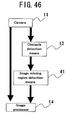
- FIG. 46 conceptually shows a basic configuration of a vehicle surroundings display device of Embodiment 4 of the present invention.
- the vehicle surroundings display device of FIG. 46 includes, as a basic configuration: a camera 11 for taking images of the surroundings of a vehicle; an obstacle detection means 12 for detecting an obstacle in the surroundings of the vehicle; an image processor 14 receiving images taken with the camera 11 (camera images) for generating an image showing the situation around the vehicle from the received camera images; and an image missing region detection means 41 for detecting an image missing region in a surroundings image.
- the image missing region detection means 41 detects an image missing region in which no image data is obtained from the camera 11 due to existence of the obstacle.
- Embodiment 4 distinguishing from Embodiment 1 is the image missing region detection means 41 .
- the image missing region detection means 41 detects an image missing region failing to obtain image data from the camera 11 when an obstacle is detected by the obstacle detection means 12 , and the image processor 14 fills at least part of the image missing region with substitute image data by interpolation and synthesis as in the embodiments described above, to complete a vehicle surroundings image.
- the image missing region detection means 41 holds arbitrary three-dimensional shape models called virtual obstacle shapes imitating rough shapes of obstacles.
- FIG. 47 shows an example of a virtual obstacle shape.
- Other virtual obstacle shapes such as a cube and any polyhedrons, and modeled shapes of actual obstacles can also be used.
- the size of a virtual obstacle shape may be determined arbitrarily. If it is presumed that a detected obstacle is a vehicle, the size may be a size of normal vehicles, such as 1.7 m W (minor side) ⁇ 4.2 m L (major side) ⁇ 1.4 mm H (height), for example. It is also possible to hold a plurality of virtual obstacle shapes, determine the type of an obstacle in the manner described in Embodiment 3, and select a virtual obstacle shape based on the determined type.
- the determined virtual obstacle shape is fitted to the region recognized as an obstacle, and a camera image is projected on the shape.
- a region of the virtual obstacle shape on which no image is projected during the projection of the camera image is considered as an image missing region.
- the image processor 14 performs image synthesis by the interpolation/superposing described above to fill the image missing region with image data, to thereby generate a surroundings image. That is, by use of a virtual obstacle shape, the image projection plane and the image missing region can be presumed simultaneously.
- FIG. 48 is a flowchart of processing in this embodiment.
- an obstacle region is detected by the obstacle detection means 12, and the length L1 of the region is measured (step S61 ) as in Embodiment 1.
- the obstacle region is obtained as a plane.
- a virtual obstacle shape is fitted to the detected obstacle region (step S62 ).
- the virtual obstacle shape a shape formed based on the shape and size of a vehicle as shown in FIG. 47 is used.
- the virtual obstacle shape is placed so that the major side is aligned with the obstacle region as shown in FIG. 50.
- the virtual obstacle shape is placed so that the minor side is aligned with the obstacle region.
- a region of the fitted virtual obstacle shape closer to the user's vehicle is determined as an image projection plane, to project an obstacle image taken with the camera on the image projection plane (step S63 ).
- the region of the fitted virtual obstacle shape other than the image projection plane is considered as an image missing region (step S64 ).
- the interpolation/superposing described above is performed for this image missing region, to thereby generate a synthesized image (step S65).
- FIGS. 52A , 52B , 53A and 53B conceptually show the results of the fitting of a virtual obstacle shape in the situation shown in FIG. 45 in which a vehicle 2 exists in the rear of the user's vehicle 1 .
- FIGS. 52A and 52B are viewed from a side, while FIGS. 53A and 53B are viewed from above.
- the application of the present invention is not limited to vehicles.
- the present invention is applicable to indoor and outdoor monitoring systems and vision systems for mobile robots.
- FIG. 54 is a conceptual view of a monitoring system in which two cameras 11A and 11B take images of a room. As shown in FIG. 54, a table TB and two chairs CH1 and CH2 are placed in the room. Images taken with the two cameras 11A and 11B are synthesized to provide a virtual viewpoint image viewed via a virtual camera VC.
- the center region of the table TB is not covered by any of the cameras 11A and 11B and thus fails to obtain image data although it is not an occlusion region. Therefore, this region constitutes an image missing region in the virtual viewpoint image. If the table TB does not exist in the room, this missing of image data will not occur. In other words, in this case, the image missing region is generated, not due to occlusion, but because no image data is obtained due to existence of the table TB as an object.
- the system is provided with a detection means for detecting an object in the monitor range (image-provided range) and an image missing region detection means for detecting an image missing region in a monitor image (provided image) when an object is detected by the detection means.
- an image processor fills the image missing region with substitute image data by the interpolation or by the method using a database image described above, for example.
- unnaturalness of the image missing region is reduced due to the filling with substitute image data, and camera image data is used for the portion other than the image missing region. Therefore, the user does not feel the provided image unnatural so much and can recognize the situation in the image-provided range accurately.
- the position of a virtual viewpoint for image synthesis was above a vehicle.
- the present invention is also applicable to cases using virtual viewpoints at positions other than this position.
- the technical idea of the present invention is also effective for generation of a vehicle surroundings image by a technique other than the virtual viewpoint transform.
- the user does not feel unnaturalness for a surroundings image so much and can recognize the position of an obstacle in the surroundings of the user's vehicle accurately.
- safe driving operation is possible more reliably and comfortably than in the conventional case.
- the image providing system of the present invention the user does not feel unnaturalness for a provided image so much and can recognize the situation in the image-provided range accurately.
Landscapes
- Physics & Mathematics (AREA)
- Electromagnetism (AREA)
- Engineering & Computer Science (AREA)
- General Physics & Mathematics (AREA)
- Radar, Positioning & Navigation (AREA)
- Remote Sensing (AREA)
- Closed-Circuit Television Systems (AREA)
- Image Processing (AREA)
- Traffic Control Systems (AREA)
- Image Analysis (AREA)
Abstract
Description

Pi(Xi0, Yi0), Qi(Xi1, Yi1), Ri(Xi2, Yi2), Si(Xi3, Yi3),
and the coordinates of the four comers of the
Pw(Xw0, Yw0, Zw0), Qw(Xw1, Yw1, Zw1), Rw(Xw2, Yw2, Zw2), Sw(Xw3, Yw3, Zw3).
Claims (13)
- A vehicle surroundings display device comprising:wherein the image processor fills at least part of the image missing region with substitute image data when the image missing region is detected.a camera for taking an image of the surroundings of a vehicle;obstacle detection means for detecting an obstacle in the surroundings of the vehicle;an image processor for generating a surroundings image representing the situation around the vehicle from the image taken with the camera; andimage missing region detection means for detecting an image missing region in the surroundings image when the obstacle is detected by the obstacle detection means, the image missing region failing to obtain image data from the camera due to existence of the obstacle,
- The device of Claim 1, wherein the image missing region detection means includes object position detection means for detecting the position of a border of the obstacle on the vehicle side, and determines the image missing region using the detected border position.
- The device of Claim 2, wherein the image processor uses a border image including at least the border portion of the obstacle on the vehicle side for generation of the substitute image data.
- The device of Claim 3, wherein the image processor places the border image on the surroundings image so as to align with the border position detected by the obstacle position detection means,
presumes a region occupied by the obstacle in the surroundings image by aligning with the border position, and
generates the substitute image data by pixel interpolation using pixel data of the border image for a portion of the presumed obstacle region other than the border image. - The device of Claim 4, wherein when the obstacle is an axisymmetric object, the image processor assumes a symmetry axis of the obstacle in the surroundings image, inverts the border image with respect to the symmetry axis to provide an inverted border image, and generates an image between the border image and the inverted border image in the obstacle region by the pixel interpolation using pixel data of the border image.
- The device of Claim 2, further comprising an obstacle image database for storing image data of objects as candidates of obstacles,
wherein the image processor determines the type of the detected obstacle, reads image data of the determined type of obstacle from the obstacle image database, places the read image data on the surroundings image to align with the border position detected by the obstacle position detection means as the substitute image data. - The device of Claim 6, wherein the image processor determines the type of the obstacle based on the image from the camera.
- The device of Claim 2, wherein when the obstacle is a vehicle, the obstacle position detection means detects a contact position of a tire of the vehicle with the road surface in the image from the camera as the border position.
- The device of Claim 2, wherein when the obstacle is a vehicle, the obstacle position detection means detects a line of a plane including a number plate of the vehicle in contact with the road surface in the image from the camera as the border position.
- The device of Claim 2, wherein the image processor generates the surroundings image by performing virtual viewpoint transform based on the image from the camera.
- An image providing system comprising:wherein the image processor fills at least part of the image missing region with substitute image data when the image missing region is detected.a camera for taking an image;detection means for detecting an object in an image-provided range;an image processor for generating a provided image showing the situation in the image-provided range from the image taken with the camera; andimage missing region detection means for detecting an image missing region in the provided image when an object is detected by the detection means, the image missing region failing to obtain image data from the camera due to existence of the object,
- The system of Claim 11, wherein the camera takes an image of the surroundings of a vehicle.
- The system of Claim 11, wherein the camera takes an image of the inside or surroundings of a building.
Applications Claiming Priority (2)
| Application Number | Priority Date | Filing Date | Title |
|---|---|---|---|
| JP2001272518 | 2001-09-07 | ||
| JP2001272518 | 2001-09-07 |
Publications (3)
| Publication Number | Publication Date |
|---|---|
| EP1291668A2 true EP1291668A2 (en) | 2003-03-12 |
| EP1291668A3 EP1291668A3 (en) | 2004-12-01 |
| EP1291668B1 EP1291668B1 (en) | 2005-11-30 |
Family
ID=19097879
Family Applications (1)
| Application Number | Title | Priority Date | Filing Date |
|---|---|---|---|
| EP02020059A Expired - Lifetime EP1291668B1 (en) | 2001-09-07 | 2002-09-06 | Vehicle surroundings display device and image providing system |
Country Status (5)
| Country | Link |
|---|---|
| US (1) | US7176959B2 (en) |
| EP (1) | EP1291668B1 (en) |
| CN (1) | CN1257070C (en) |
| AT (1) | ATE311725T1 (en) |
| DE (1) | DE60207655T2 (en) |
Cited By (10)
| Publication number | Priority date | Publication date | Assignee | Title |
|---|---|---|---|---|
| WO2008028568A1 (en) * | 2006-09-07 | 2008-03-13 | Bayerische Motoren Werke Aktiengesellschaft | Driver assistance system with object detection facility |
| WO2008055644A3 (en) * | 2006-11-09 | 2009-07-09 | Bayerische Motoren Werke Ag | Method for the generation of a full image of the surroundings of a motor vehicle |
| WO2013107548A1 (en) * | 2012-01-19 | 2013-07-25 | Robert Bosch Gmbh | Method and device for visualizing the surroundings of a vehicle |
| EP2720458A4 (en) * | 2011-06-09 | 2015-02-25 | Aisin Seiki | IMAGE GENERATING DEVICE |
| WO2015092981A1 (en) * | 2013-12-16 | 2015-06-25 | Sony Corporation | Image processing apparatus, image processing method, and program |
| EP2414776A4 (en) * | 2009-03-30 | 2016-02-17 | Delphi Tech Inc | APPARATUS FOR HANDLING A VEHICLE |
| US20160291387A1 (en) * | 2015-04-03 | 2016-10-06 | Kabushiki Kaisha Toshiba | Medical monitor, electronic apparatus, and video display unit |
| US20170132476A1 (en) * | 2015-11-08 | 2017-05-11 | Otobrite Electronics Inc. | Vehicle Imaging System |
| US11615628B2 (en) | 2018-02-02 | 2023-03-28 | Sony Corporation | Information processing apparatus, information processing method, and mobile object |
| CN121224683A (en) * | 2025-12-02 | 2025-12-30 | 纽劢科技(上海)有限公司 | Methods and electronic devices for generating reference lines in vehicle path planning |
Families Citing this family (80)
| Publication number | Priority date | Publication date | Assignee | Title |
|---|---|---|---|---|
| WO2005088970A1 (en) * | 2004-03-11 | 2005-09-22 | Olympus Corporation | Image generation device, image generation method, and image generation program |
| US7561720B2 (en) * | 2004-04-30 | 2009-07-14 | Visteon Global Technologies, Inc. | Single camera system and method for range and lateral position measurement of a preceding vehicle |
| WO2005114375A1 (en) * | 2004-05-21 | 2005-12-01 | Computer Associates Think, Inc. | Systems and methods for tracking screen updates |
| JP3934119B2 (en) * | 2004-06-14 | 2007-06-20 | 本田技研工業株式会社 | Vehicle periphery monitoring device |
| US7629995B2 (en) * | 2004-08-06 | 2009-12-08 | Sony Corporation | System and method for correlating camera views |
| JP4639753B2 (en) * | 2004-10-25 | 2011-02-23 | 日産自動車株式会社 | Driving assistance device |
| US7561721B2 (en) * | 2005-02-02 | 2009-07-14 | Visteon Global Technologies, Inc. | System and method for range measurement of a preceding vehicle |
| JPWO2006109398A1 (en) * | 2005-03-15 | 2008-10-09 | オムロン株式会社 | Image processing apparatus and method, program, and recording medium |
| JP2006259895A (en) * | 2005-03-15 | 2006-09-28 | Omron Corp | Moving body start control device |
| JP4305412B2 (en) * | 2005-05-10 | 2009-07-29 | 株式会社デンソー | Obstacle detection device |
| WO2007015446A1 (en) * | 2005-08-02 | 2007-02-08 | Nissan Motor Co., Ltd. | Device for monitoring around vehicle and method for monitoring around vehicle |
| US20070031008A1 (en) * | 2005-08-02 | 2007-02-08 | Visteon Global Technologies, Inc. | System and method for range measurement of a preceding vehicle |
| FR2891934B1 (en) * | 2005-10-12 | 2008-01-18 | Valeo Electronique Sys Liaison | DEVICE FOR PROCESSING VIDEO DATA FOR A MOTOR VEHICLE |
| JP4934308B2 (en) * | 2005-10-17 | 2012-05-16 | 三洋電機株式会社 | Driving support system |
| US7623681B2 (en) * | 2005-12-07 | 2009-11-24 | Visteon Global Technologies, Inc. | System and method for range measurement of a preceding vehicle |
| JP4956799B2 (en) * | 2006-05-09 | 2012-06-20 | 日産自動車株式会社 | Vehicle surrounding image providing apparatus and vehicle surrounding image providing method |
| US20090128630A1 (en) * | 2006-07-06 | 2009-05-21 | Nissan Motor Co., Ltd. | Vehicle image display system and image display method |
| JP4254887B2 (en) * | 2006-07-06 | 2009-04-15 | 日産自動車株式会社 | Image display system for vehicles |
| WO2008065717A1 (en) * | 2006-11-29 | 2008-06-05 | Fujitsu Limited | Pedestrian detecting system, and pedestrian detecting method |
| KR100857330B1 (en) * | 2006-12-12 | 2008-09-05 | 현대자동차주식회사 | Parking track recognition device and automatic parking system |
| KR100858087B1 (en) * | 2007-02-14 | 2008-09-10 | 삼성전자주식회사 | Object Pose Normalization Method and Device and Object Recognition Method |
| WO2009038146A1 (en) * | 2007-09-20 | 2009-03-26 | Canon Kabushiki Kaisha | Image detection device and image detection method |
| JP5057936B2 (en) * | 2007-11-09 | 2012-10-24 | アルパイン株式会社 | Bird's-eye image generation apparatus and method |
| JP4874280B2 (en) * | 2008-03-19 | 2012-02-15 | 三洋電機株式会社 | Image processing apparatus and method, driving support system, and vehicle |
| CN101266132B (en) * | 2008-04-30 | 2011-08-10 | 西安工业大学 | Running disorder detection method based on MPFG movement vector |
| US8150105B2 (en) * | 2008-05-22 | 2012-04-03 | International Electronic Machines Corporation | Inspection using three-dimensional profile information |
| JP5068779B2 (en) * | 2009-02-27 | 2012-11-07 | 現代自動車株式会社 | Vehicle surroundings overhead image display apparatus and method |
| JP5190712B2 (en) * | 2009-03-24 | 2013-04-24 | アイシン精機株式会社 | Obstacle detection device |
| US8416300B2 (en) * | 2009-05-20 | 2013-04-09 | International Business Machines Corporation | Traffic system for enhancing driver visibility |
| JP5143235B2 (en) * | 2009-10-07 | 2013-02-13 | パナソニック株式会社 | Control device and vehicle surrounding monitoring device |
| CN101847154A (en) * | 2010-02-26 | 2010-09-29 | 宇龙计算机通信科技(深圳)有限公司 | Method and system for inquiring information and method for mobile terminal to inquire information |
| WO2011145141A1 (en) * | 2010-05-19 | 2011-11-24 | 三菱電機株式会社 | Vehicle rear-view observation device |
| DE112010005661B4 (en) * | 2010-06-15 | 2014-10-30 | Mitsubishi Electric Corporation | Vehicle environment monitoring device |
| DE102010042026B4 (en) * | 2010-10-06 | 2020-11-26 | Robert Bosch Gmbh | Method for generating an image of at least one object in the surroundings of a vehicle |
| US8983717B2 (en) * | 2010-12-21 | 2015-03-17 | Ford Global Technologies, Llc | Vehicle camera system operable in off-road mode and method |
| JP5724570B2 (en) * | 2011-04-18 | 2015-05-27 | 日産自動車株式会社 | Driving support device and driving support method |
| DE102011084554A1 (en) * | 2011-10-14 | 2013-04-18 | Robert Bosch Gmbh | Method for displaying a vehicle environment |
| WO2013066601A1 (en) * | 2011-10-17 | 2013-05-10 | Kimmel Zebadiah M | Method and apparatus for monitoring individuals while protecting their privacy |
| WO2013058985A1 (en) | 2011-10-17 | 2013-04-25 | Kimmel Zebadiah M | Method and apparatus for detecting deterioration of health status |
| WO2013058978A1 (en) | 2011-10-17 | 2013-04-25 | Kimmel Zebadiah M | Method and apparatus for sizing and fitting an individual for apparel, accessories, or prosthetics |
| DE102012203092A1 (en) * | 2012-02-29 | 2013-08-29 | Bayerische Motoren Werke Aktiengesellschaft | Method for image processing of image data of image detected by camera, involves determining availability of predetermined object type depending on image data of image, where position is determined with respect to planimetric projection |
| DE102012203171A1 (en) * | 2012-02-29 | 2013-08-29 | Bayerische Motoren Werke Aktiengesellschaft | Method for processing image data of images captured by cameras arranged on e.g. car, involves determining image data onto surface of environment model based on preset position of virtual camera and environment model image data |
| DE102012203523A1 (en) * | 2012-03-06 | 2013-09-12 | Bayerische Motoren Werke Aktiengesellschaft | Method for processing image data of cameras mounted in vehicle, involves determining image data to be signaled from view of virtual camera on surface of three-dimensional environment model |
| US9881354B2 (en) * | 2012-03-15 | 2018-01-30 | Microsoft Technology Licensing, Llc | Image completion including automatic cropping |
| DE102012014466A1 (en) * | 2012-07-21 | 2014-01-23 | Volkswagen Aktiengesellschaft | Method for representation of scene for vehicle e.g. motor car, involves calculating image which shows scene from view of virtual camera depending on image while displaying image on display of vehicle |
| KR101376210B1 (en) * | 2012-08-06 | 2014-03-21 | 현대모비스 주식회사 | Around View Monitor System and Monitoring Method |
| DE102012018326B4 (en) * | 2012-09-15 | 2019-12-19 | Zf Friedrichshafen Ag | Method and device for an imaging driver assistance system with concealment-free foresight function |
| US9656690B2 (en) | 2012-10-30 | 2017-05-23 | Robert Bosch Gmbh | System and method for using gestures in autonomous parking |
| TWI505203B (en) * | 2012-11-02 | 2015-10-21 | Avisonic Technology Corp | Image processing method and image processing apparatus for generating vehicular image |
| EP2920566A4 (en) * | 2012-11-15 | 2016-07-13 | Android Ind Llc | System and method for determining uniformity of a tire |
| DE102013211126A1 (en) * | 2013-06-14 | 2014-12-18 | Robert Bosch Gmbh | Method for modeling an environment of a vehicle |
| KR101439052B1 (en) * | 2013-09-05 | 2014-09-05 | 현대자동차주식회사 | Apparatus and method for detecting obstacle |
| JP6291866B2 (en) * | 2014-01-27 | 2018-03-14 | 株式会社デンソー | Driving support device and driving support method |
| US9600993B2 (en) | 2014-01-27 | 2017-03-21 | Atlas5D, Inc. | Method and system for behavior detection |
| JP6075331B2 (en) * | 2014-06-13 | 2017-02-08 | トヨタ自動車株式会社 | Vehicle lighting device |
| US9990550B2 (en) * | 2014-09-19 | 2018-06-05 | Bendix Commercial Vehicle Systems Llc | Wide baseline object detection stereo system |
| EP3001272B1 (en) * | 2014-09-26 | 2017-04-12 | Volvo Car Corporation | Method of trajectory planning for yielding manoeuvres |
| JP6365238B2 (en) * | 2014-10-29 | 2018-08-01 | 株式会社デンソー | Parking assistance device |
| KR101637716B1 (en) * | 2014-11-03 | 2016-07-07 | 현대자동차주식회사 | Apparatus and method for recognizing position of obstacle in vehicle |
| KR102289477B1 (en) * | 2015-01-30 | 2021-08-13 | 현대모비스 주식회사 | Apparatus for Parking assistance |
| US10013756B2 (en) | 2015-03-13 | 2018-07-03 | Atlas5D, Inc. | Methods and systems for measuring use of an assistive device for ambulation |
| TWI559267B (en) * | 2015-12-04 | 2016-11-21 | Method of quantifying the reliability of obstacle classification | |
| JP6318183B2 (en) | 2016-01-20 | 2018-04-25 | 株式会社Subaru | Image processing device |
| JP6203461B1 (en) * | 2016-02-12 | 2017-09-27 | 三菱電機株式会社 | Information display device and information display method |
| CN106004661B (en) * | 2016-05-31 | 2018-12-07 | 百度在线网络技术(北京)有限公司 | Exterior rearview mirror system and method applied to the exterior rearview mirror system |
| DE102016114693A1 (en) * | 2016-08-09 | 2018-02-15 | Connaught Electronics Ltd. | A method for assisting a driver of a motor vehicle when driving the motor vehicle, driver assistance system and motor vehicle |
| US10151830B2 (en) * | 2016-09-14 | 2018-12-11 | Caterpillar Inc. | Systems and methods for detecting objects proximate to a machine utilizing a learned process |
| JP6766557B2 (en) | 2016-09-29 | 2020-10-14 | アイシン精機株式会社 | Peripheral monitoring device |
| JPWO2018197984A1 (en) * | 2017-04-28 | 2020-03-19 | 株式会社半導体エネルギー研究所 | Display system and moving object |
| JP6980897B2 (en) | 2018-03-12 | 2021-12-15 | 日立Astemo株式会社 | Vehicle control device |
| CN108909625B (en) * | 2018-06-22 | 2021-09-17 | 河海大学常州校区 | Vehicle bottom ground display method based on panoramic all-round viewing system |
| DE102018210812A1 (en) * | 2018-06-30 | 2020-01-02 | Robert Bosch Gmbh | Method for a sensor- and memory-based representation of an environment, display device and vehicle with the display device |
| US11520331B2 (en) * | 2018-12-28 | 2022-12-06 | Intel Corporation | Methods and apparatus to update autonomous vehicle perspectives |
| CN112124199B (en) * | 2019-06-24 | 2024-04-12 | 博世汽车部件(苏州)有限公司 | Imaging method and imaging system for vehicle running road conditions and vehicle |
| CN111538329B (en) * | 2020-04-09 | 2023-02-28 | 北京石头创新科技有限公司 | Image viewing method, terminal and cleaning machine |
| JP7654966B2 (en) * | 2020-12-04 | 2025-04-02 | 株式会社アイシン | Periphery monitoring device |
| WO2022204854A1 (en) * | 2021-03-29 | 2022-10-06 | 华为技术有限公司 | Method for acquiring blind zone image, and related terminal apparatus |
| CN113242510B (en) * | 2021-04-30 | 2024-05-17 | 深圳市慧鲤科技有限公司 | Exit guiding method and device for parking lot, electronic equipment and storage medium |
| JP7547304B2 (en) * | 2021-10-29 | 2024-09-09 | キヤノン株式会社 | Image processing device, image processing method, and program |
| CN115761659B (en) * | 2023-01-09 | 2023-04-11 | 南京隼眼电子科技有限公司 | Recognition model construction method, vehicle type recognition method, electronic device, and storage medium |
Family Cites Families (14)
| Publication number | Priority date | Publication date | Assignee | Title |
|---|---|---|---|---|
| JPS58110334A (en) | 1981-12-23 | 1983-06-30 | Hino Motors Ltd | Road-surface visual-range indicator |
| JPS59120877A (en) * | 1982-12-27 | 1984-07-12 | Aisin Seiki Co Ltd | Distance indicator on vehicle |
| JPH06333200A (en) | 1993-05-21 | 1994-12-02 | Toshiba Corp | On-vehicle supervisory system |
| JP3102250B2 (en) | 1994-02-14 | 2000-10-23 | 三菱自動車工業株式会社 | Ambient information display device for vehicles |
| JP3192875B2 (en) * | 1994-06-30 | 2001-07-30 | キヤノン株式会社 | Image synthesis method and image synthesis device |
| US6008865A (en) * | 1997-02-14 | 1999-12-28 | Eastman Kodak Company | Segmentation-based method for motion-compensated frame interpolation |
| JPH10302074A (en) | 1997-04-25 | 1998-11-13 | Chuo Spring Co Ltd | License plate position detector |
| JP3596314B2 (en) * | 1998-11-02 | 2004-12-02 | 日産自動車株式会社 | Object edge position measuring device and moving object traffic judging device |
| EP1179958B1 (en) | 1999-04-16 | 2012-08-08 | Panasonic Corporation | Image processing device and monitoring system |
| JP4312883B2 (en) | 1999-06-29 | 2009-08-12 | 富士通テン株式会社 | Vehicle parking assist device |
| DE10037130B4 (en) * | 1999-09-13 | 2015-10-29 | Volkswagen Ag | Parking and / or Rangierhilfeeinrichtung for cars or trucks |
| JP3680658B2 (en) * | 1999-09-30 | 2005-08-10 | 松下電器産業株式会社 | Image recognition method and image recognition apparatus |
| JP3494434B2 (en) | 1999-10-21 | 2004-02-09 | 松下電器産業株式会社 | Parking assistance device |
| US6734896B2 (en) * | 2000-04-28 | 2004-05-11 | Matsushita Electric Industrial Co., Ltd. | Image processor and monitoring system |
-
2002
- 2002-09-06 DE DE60207655T patent/DE60207655T2/en not_active Expired - Lifetime
- 2002-09-06 AT AT02020059T patent/ATE311725T1/en not_active IP Right Cessation
- 2002-09-06 EP EP02020059A patent/EP1291668B1/en not_active Expired - Lifetime
- 2002-09-09 CN CNB021416516A patent/CN1257070C/en not_active Expired - Lifetime
- 2002-09-09 US US10/237,514 patent/US7176959B2/en not_active Expired - Lifetime
Cited By (18)
| Publication number | Priority date | Publication date | Assignee | Title |
|---|---|---|---|---|
| US8093999B2 (en) | 2006-09-07 | 2012-01-10 | Bayerische Motoren Werke Aktiengesellschaft | Driver assistance system and method with object detection facility |
| WO2008028568A1 (en) * | 2006-09-07 | 2008-03-13 | Bayerische Motoren Werke Aktiengesellschaft | Driver assistance system with object detection facility |
| WO2008055644A3 (en) * | 2006-11-09 | 2009-07-09 | Bayerische Motoren Werke Ag | Method for the generation of a full image of the surroundings of a motor vehicle |
| EP2414776A4 (en) * | 2009-03-30 | 2016-02-17 | Delphi Tech Inc | APPARATUS FOR HANDLING A VEHICLE |
| EP2720458A4 (en) * | 2011-06-09 | 2015-02-25 | Aisin Seiki | IMAGE GENERATING DEVICE |
| KR20140114373A (en) * | 2012-01-19 | 2014-09-26 | 로베르트 보쉬 게엠베하 | Method and device for visualizing the surroundings of a vehicle |
| CN104204847A (en) * | 2012-01-19 | 2014-12-10 | 罗伯特·博世有限公司 | Method and device for visualizing the surroundings of a vehicle |
| WO2013107548A1 (en) * | 2012-01-19 | 2013-07-25 | Robert Bosch Gmbh | Method and device for visualizing the surroundings of a vehicle |
| CN104204847B (en) * | 2012-01-19 | 2017-12-08 | 罗伯特·博世有限公司 | For the method and apparatus for the surrounding environment for visualizing vehicle |
| US9862316B2 (en) | 2012-01-19 | 2018-01-09 | Robert Bosch Gmbh | Method and device for visualizing the surroundings of a vehicle |
| WO2015092981A1 (en) * | 2013-12-16 | 2015-06-25 | Sony Corporation | Image processing apparatus, image processing method, and program |
| US10140775B2 (en) | 2013-12-16 | 2018-11-27 | Sony Corporation | Image processing apparatus, image processing method, and program |
| US20160291387A1 (en) * | 2015-04-03 | 2016-10-06 | Kabushiki Kaisha Toshiba | Medical monitor, electronic apparatus, and video display unit |
| US10036908B2 (en) * | 2015-04-03 | 2018-07-31 | Toshiba Visual Solutions Corporation | Medical monitor, electronic apparatus, and video display unit |
| US20170132476A1 (en) * | 2015-11-08 | 2017-05-11 | Otobrite Electronics Inc. | Vehicle Imaging System |
| CN107021015A (en) * | 2015-11-08 | 2017-08-08 | 欧特明电子股份有限公司 | System and method for image processing |
| US11615628B2 (en) | 2018-02-02 | 2023-03-28 | Sony Corporation | Information processing apparatus, information processing method, and mobile object |
| CN121224683A (en) * | 2025-12-02 | 2025-12-30 | 纽劢科技(上海)有限公司 | Methods and electronic devices for generating reference lines in vehicle path planning |
Also Published As
| Publication number | Publication date |
|---|---|
| EP1291668A3 (en) | 2004-12-01 |
| CN1406790A (en) | 2003-04-02 |
| DE60207655T2 (en) | 2006-06-08 |
| DE60207655D1 (en) | 2006-01-05 |
| US20030076414A1 (en) | 2003-04-24 |
| ATE311725T1 (en) | 2005-12-15 |
| US7176959B2 (en) | 2007-02-13 |
| EP1291668B1 (en) | 2005-11-30 |
| CN1257070C (en) | 2006-05-24 |
Similar Documents
| Publication | Publication Date | Title |
|---|---|---|
| EP1291668B1 (en) | Vehicle surroundings display device and image providing system | |
| JP3606853B2 (en) | Vehicle ambient condition display device | |
| US6819779B1 (en) | Lane detection system and apparatus | |
| EP4145339B1 (en) | Vehicle drivable area detection method and system | |
| EP3418943B1 (en) | Object detecting apparatus, object detecting method, and computer-readable medium | |
| JP3367170B2 (en) | Obstacle detection device | |
| US7110021B2 (en) | Vehicle surroundings monitoring device, and image production method/program | |
| JP4861574B2 (en) | Driving assistance device | |
| US7706572B2 (en) | Obstacle detection system and method therefor | |
| JP4406381B2 (en) | Obstacle detection apparatus and method | |
| US12100190B2 (en) | Perception system for autonomous vehicles | |
| EP4246467B1 (en) | Electronic instrument, movable apparatus, distance calculation method, and storage medium | |
| Broggi et al. | A multi-resolution approach for infrared vision-based pedestrian detection | |
| CN113780050A (en) | Advanced driver assistance system and method for detecting objects therein | |
| JP4344860B2 (en) | Road plan area and obstacle detection method using stereo image | |
| US11373389B2 (en) | Partitioning images obtained from an autonomous vehicle camera | |
| JP5083443B2 (en) | Driving support device and method, and arithmetic device | |
| EP4148375A1 (en) | Ranging method and apparatus | |
| JP2012198857A (en) | Approaching object detector and approaching object detection method | |
| CN116912788B (en) | Attack detection method, device and equipment for automatic driving system and storage medium | |
| US11461922B2 (en) | Depth estimation in images obtained from an autonomous vehicle camera | |
| Li et al. | The research of vehicle monocular ranging based on YOlOv5 | |
| CN110488320B (en) | A Method of Using Stereo Vision to Detect Vehicle Distance | |
| JP2002352249A (en) | Image processing apparatus and method | |
| JP2022152835A (en) | Information processor, vehicle, roadside machine, and information processing method |
Legal Events
| Date | Code | Title | Description |
|---|---|---|---|
| PUAI | Public reference made under article 153(3) epc to a published international application that has entered the european phase |
Free format text: ORIGINAL CODE: 0009012 |
|
| AK | Designated contracting states |
Kind code of ref document: A2 Designated state(s): AT BE BG CH CY CZ DE DK EE ES FI FR GB GR IE IT LI LU MC NL PT SE SK TR Designated state(s): AT BE BG CH CY CZ DE DK EE ES FI FR GB GR IE IT LI LU MC NL PT SE SK TR |
|
| AX | Request for extension of the european patent |
Extension state: AL LT LV MK RO SI |
|
| PUAL | Search report despatched |
Free format text: ORIGINAL CODE: 0009013 |
|
| AK | Designated contracting states |
Kind code of ref document: A3 Designated state(s): AT BE BG CH CY CZ DE DK EE ES FI FR GB GR IE IT LI LU MC NL PT SE SK TR |
|
| AX | Request for extension of the european patent |
Extension state: AL LT LV MK RO SI |
|
| RIC1 | Information provided on ipc code assigned before grant |
Ipc: 7H 04N 7/18 A Ipc: 7B 60R 1/00 B |
|
| GRAP | Despatch of communication of intention to grant a patent |
Free format text: ORIGINAL CODE: EPIDOSNIGR1 |
|
| 17P | Request for examination filed |
Effective date: 20050128 |
|
| RIC1 | Information provided on ipc code assigned before grant |
Ipc: 7H 04N 7/18 A Ipc: 7B 60R 1/00 B Ipc: 7G 01S 11/12 B |
|
| GRAS | Grant fee paid |
Free format text: ORIGINAL CODE: EPIDOSNIGR3 |
|
| AKX | Designation fees paid |
Designated state(s): AT BE BG CH CY CZ DE DK EE ES FI FR GB GR IE IT LI LU MC NL PT SE SK TR |
|
| GRAA | (expected) grant |
Free format text: ORIGINAL CODE: 0009210 |
|
| AK | Designated contracting states |
Kind code of ref document: B1 Designated state(s): AT BE BG CH CY CZ DE DK EE ES FI FR GB GR IE IT LI LU MC NL PT SE SK TR |
|
| PG25 | Lapsed in a contracting state [announced via postgrant information from national office to epo] |
Ref country code: AT Free format text: LAPSE BECAUSE OF FAILURE TO SUBMIT A TRANSLATION OF THE DESCRIPTION OR TO PAY THE FEE WITHIN THE PRESCRIBED TIME-LIMIT Effective date: 20051130 Ref country code: SK Free format text: LAPSE BECAUSE OF FAILURE TO SUBMIT A TRANSLATION OF THE DESCRIPTION OR TO PAY THE FEE WITHIN THE PRESCRIBED TIME-LIMIT Effective date: 20051130 Ref country code: NL Free format text: LAPSE BECAUSE OF FAILURE TO SUBMIT A TRANSLATION OF THE DESCRIPTION OR TO PAY THE FEE WITHIN THE PRESCRIBED TIME-LIMIT Effective date: 20051130 Ref country code: LI Free format text: LAPSE BECAUSE OF FAILURE TO SUBMIT A TRANSLATION OF THE DESCRIPTION OR TO PAY THE FEE WITHIN THE PRESCRIBED TIME-LIMIT Effective date: 20051130 Ref country code: BE Free format text: LAPSE BECAUSE OF FAILURE TO SUBMIT A TRANSLATION OF THE DESCRIPTION OR TO PAY THE FEE WITHIN THE PRESCRIBED TIME-LIMIT Effective date: 20051130 Ref country code: FI Free format text: LAPSE BECAUSE OF FAILURE TO SUBMIT A TRANSLATION OF THE DESCRIPTION OR TO PAY THE FEE WITHIN THE PRESCRIBED TIME-LIMIT Effective date: 20051130 Ref country code: CH Free format text: LAPSE BECAUSE OF FAILURE TO SUBMIT A TRANSLATION OF THE DESCRIPTION OR TO PAY THE FEE WITHIN THE PRESCRIBED TIME-LIMIT Effective date: 20051130 Ref country code: CZ Free format text: LAPSE BECAUSE OF FAILURE TO SUBMIT A TRANSLATION OF THE DESCRIPTION OR TO PAY THE FEE WITHIN THE PRESCRIBED TIME-LIMIT Effective date: 20051130 |
|
| REG | Reference to a national code |
Ref country code: CH Ref legal event code: EP Ref country code: GB Ref legal event code: FG4D |
|
| REG | Reference to a national code |
Ref country code: IE Ref legal event code: FG4D |
|
| REF | Corresponds to: |
Ref document number: 60207655 Country of ref document: DE Date of ref document: 20060105 Kind code of ref document: P |
|
| PG25 | Lapsed in a contracting state [announced via postgrant information from national office to epo] |
Ref country code: GR Free format text: LAPSE BECAUSE OF FAILURE TO SUBMIT A TRANSLATION OF THE DESCRIPTION OR TO PAY THE FEE WITHIN THE PRESCRIBED TIME-LIMIT Effective date: 20060228 Ref country code: SE Free format text: LAPSE BECAUSE OF FAILURE TO SUBMIT A TRANSLATION OF THE DESCRIPTION OR TO PAY THE FEE WITHIN THE PRESCRIBED TIME-LIMIT Effective date: 20060228 Ref country code: DK Free format text: LAPSE BECAUSE OF FAILURE TO SUBMIT A TRANSLATION OF THE DESCRIPTION OR TO PAY THE FEE WITHIN THE PRESCRIBED TIME-LIMIT Effective date: 20060228 Ref country code: BG Free format text: LAPSE BECAUSE OF FAILURE TO SUBMIT A TRANSLATION OF THE DESCRIPTION OR TO PAY THE FEE WITHIN THE PRESCRIBED TIME-LIMIT Effective date: 20060228 |
|
| PG25 | Lapsed in a contracting state [announced via postgrant information from national office to epo] |
Ref country code: ES Free format text: LAPSE BECAUSE OF FAILURE TO SUBMIT A TRANSLATION OF THE DESCRIPTION OR TO PAY THE FEE WITHIN THE PRESCRIBED TIME-LIMIT Effective date: 20060313 |
|
| PG25 | Lapsed in a contracting state [announced via postgrant information from national office to epo] |
Ref country code: PT Free format text: LAPSE BECAUSE OF FAILURE TO SUBMIT A TRANSLATION OF THE DESCRIPTION OR TO PAY THE FEE WITHIN THE PRESCRIBED TIME-LIMIT Effective date: 20060502 |
|
| NLV1 | Nl: lapsed or annulled due to failure to fulfill the requirements of art. 29p and 29m of the patents act | ||
| REG | Reference to a national code |
Ref country code: CH Ref legal event code: PL |
|
| ET | Fr: translation filed | ||
| PG25 | Lapsed in a contracting state [announced via postgrant information from national office to epo] |
Ref country code: IE Free format text: LAPSE BECAUSE OF NON-PAYMENT OF DUE FEES Effective date: 20060906 |
|
| PG25 | Lapsed in a contracting state [announced via postgrant information from national office to epo] |
Ref country code: MC Free format text: LAPSE BECAUSE OF NON-PAYMENT OF DUE FEES Effective date: 20060930 |
|
| PLBE | No opposition filed within time limit |
Free format text: ORIGINAL CODE: 0009261 |
|
| STAA | Information on the status of an ep patent application or granted ep patent |
Free format text: STATUS: NO OPPOSITION FILED WITHIN TIME LIMIT |
|
| 26N | No opposition filed |
Effective date: 20060831 |
|
| REG | Reference to a national code |
Ref country code: IE Ref legal event code: MM4A |
|
| PG25 | Lapsed in a contracting state [announced via postgrant information from national office to epo] |
Ref country code: EE Free format text: LAPSE BECAUSE OF FAILURE TO SUBMIT A TRANSLATION OF THE DESCRIPTION OR TO PAY THE FEE WITHIN THE PRESCRIBED TIME-LIMIT Effective date: 20051130 |
|
| PG25 | Lapsed in a contracting state [announced via postgrant information from national office to epo] |
Ref country code: LU Free format text: LAPSE BECAUSE OF NON-PAYMENT OF DUE FEES Effective date: 20060906 Ref country code: TR Free format text: LAPSE BECAUSE OF FAILURE TO SUBMIT A TRANSLATION OF THE DESCRIPTION OR TO PAY THE FEE WITHIN THE PRESCRIBED TIME-LIMIT Effective date: 20051130 |
|
| PG25 | Lapsed in a contracting state [announced via postgrant information from national office to epo] |
Ref country code: CY Free format text: LAPSE BECAUSE OF FAILURE TO SUBMIT A TRANSLATION OF THE DESCRIPTION OR TO PAY THE FEE WITHIN THE PRESCRIBED TIME-LIMIT Effective date: 20051130 |
|
| REG | Reference to a national code |
Ref country code: FR Ref legal event code: PLFP Year of fee payment: 15 |
|
| REG | Reference to a national code |
Ref country code: FR Ref legal event code: PLFP Year of fee payment: 16 |
|
| REG | Reference to a national code |
Ref country code: FR Ref legal event code: PLFP Year of fee payment: 17 |
|
| PGFP | Annual fee paid to national office [announced via postgrant information from national office to epo] |
Ref country code: FR Payment date: 20210812 Year of fee payment: 20 Ref country code: IT Payment date: 20210811 Year of fee payment: 20 |
|
| PGFP | Annual fee paid to national office [announced via postgrant information from national office to epo] |
Ref country code: DE Payment date: 20210727 Year of fee payment: 20 Ref country code: GB Payment date: 20210728 Year of fee payment: 20 |
|
| REG | Reference to a national code |
Ref country code: DE Ref legal event code: R071 Ref document number: 60207655 Country of ref document: DE |
|
| REG | Reference to a national code |
Ref country code: GB Ref legal event code: PE20 Expiry date: 20220905 |
|
| PG25 | Lapsed in a contracting state [announced via postgrant information from national office to epo] |
Ref country code: GB Free format text: LAPSE BECAUSE OF EXPIRATION OF PROTECTION Effective date: 20220905 |