EP1291994A2 - Dichtvorrichtung für ein Installationsgerät, sowie Anordnung mit einer Dichtvorrichtung, einem Installationsgerät und einer Unterputzdose - Google Patents
Dichtvorrichtung für ein Installationsgerät, sowie Anordnung mit einer Dichtvorrichtung, einem Installationsgerät und einer Unterputzdose Download PDFInfo
- Publication number
- EP1291994A2 EP1291994A2 EP02018899A EP02018899A EP1291994A2 EP 1291994 A2 EP1291994 A2 EP 1291994A2 EP 02018899 A EP02018899 A EP 02018899A EP 02018899 A EP02018899 A EP 02018899A EP 1291994 A2 EP1291994 A2 EP 1291994A2
- Authority
- EP
- European Patent Office
- Prior art keywords
- sealing
- flush
- mounted box
- sealing lip
- flange plate
- Prior art date
- Legal status (The legal status is an assumption and is not a legal conclusion. Google has not performed a legal analysis and makes no representation as to the accuracy of the status listed.)
- Withdrawn
Links
- 238000007789 sealing Methods 0.000 title claims description 64
- 238000009434 installation Methods 0.000 title claims description 28
- 239000000725 suspension Substances 0.000 claims description 6
- 239000000463 material Substances 0.000 claims description 4
- 229920002457 flexible plastic Polymers 0.000 claims 1
- 239000007921 spray Substances 0.000 abstract description 2
- XLYOFNOQVPJJNP-UHFFFAOYSA-N water Substances O XLYOFNOQVPJJNP-UHFFFAOYSA-N 0.000 description 13
- 230000000694 effects Effects 0.000 description 9
- 239000004575 stone Substances 0.000 description 2
- 239000002360 explosive Substances 0.000 description 1
- 230000002349 favourable effect Effects 0.000 description 1
- 230000035515 penetration Effects 0.000 description 1
- 229920001296 polysiloxane Polymers 0.000 description 1
- 239000000565 sealant Substances 0.000 description 1
Images

Classifications
-
- H—ELECTRICITY
- H02—GENERATION; CONVERSION OR DISTRIBUTION OF ELECTRIC POWER
- H02G—INSTALLATION OF ELECTRIC CABLES OR LINES, OR OF COMBINED OPTICAL AND ELECTRIC CABLES OR LINES
- H02G3/00—Installations of electric cables or lines or protective tubing therefor in or on buildings, equivalent structures or vehicles
- H02G3/02—Details
- H02G3/08—Distribution boxes; Connection or junction boxes
- H02G3/088—Dustproof, splashproof, drip-proof, waterproof, or flameproof casings or inlets
Definitions
- flush-mounted devices e.g. Switches and sockets
- VDE regulations e.g. VDE regulations
- a ring seal This applies in particular to the spray water test for the "stepped stone wall”.
- This sealing has the disadvantage that splash water from the Wall on the cover, and thus possibly from the front into the installation device, e.g. into an electrical outlet can.
- the invention has for its object a simple Specify sealing device and arrangement in which an improved Splash water protection for built-in installation devices is.
- a sealing device for an installation device which can be arranged in a flush-mounted box with a tubular base body which has a flange plate and the installation device can be arranged comprehensively in the flush-mounted box, wherein the base body has at least partially on its periphery a sealing lip which serves to seal off the flush-mounted box, wherein the sealing lip and the flange are spaced apart, and the edge of the flange plate at least partially on its side facing away from the sealing lip has a sealing projection for contacting the edge on the suspension bracket of the installation device.
- the sealing lip preferably has a pair of lips, whereby a good sealing effect against the flush-mounted box is.
- the sealing lip comprises approximately half the circumference of the tubular Basic body includes, being a flexible material Plastic is used.
- the flange plate and sealing lip should at least be about Be 0.5 cm apart. This results in a favorable space effect.
- a sealing device 1 is shown, which in a Flush box 4 is arranged.
- the sealing device 1 is thereby between an installation device 5, in particular a Socket insert, and the flush-mounted box 4 arranged.
- the Installation device 5 has a so-called hanging bracket 2 on which in a cover or frame 3 on the back is applied.
- the installation device has a splash protection 5 a hinged lid 6.
- the reference numeral 7 denotes a wall in which the entire arrangement can be installed.
- the sealing device 1 has on its tubular base body 8 on the end a flange plate 1a, which on the back rests on the hanging bracket 2.
- the flange plate 1a instructs their outer edge at least partially, especially in the installed position at the top, a projection 1c. This is in the present due to a kink or an angle in the Flange plate achieved.
- the projection 1c forms one sealing effect to the rear of the installation device 5, especially for the hanging bracket 2 and / or the frame 3.
- the sealing device 1 has inside the flush-mounted box 4 a sealing lip, in particular a pair of sealing lips 1b, which also has a sealing effect, at least in the upper area compared to the flush-mounted box.
- the sealing lip in particular the pair of sealing lips 1b, are executed such that they also use different Flush boxes always achieve an optimal effect.
- the distance between flange plate 1a and the one assigned to it Sealing lip 1b is at least about 0.5 cm. To this Achieved an effective gutter effect.
- the sealing device 1 made of an elastic plastic, in particular a silicone or rubber-like plastic. This is a good sealing effect to the adjacent ones Share guaranteed.
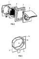
- FIG 2 the arrangement without a flush-mounted box is explosive shown spatially for assembly using an electrical outlet.
- FIG 3 shows the sealing device 1 in a spatial representation from a rear view.
- the sealing lip 1b the tubular Base body 8 of the sealing device 1 approximately at half its circumference, especially on the sides and on the top side, encloses.
- the sealing lip 1b or a pair of sealing lips a radical sealing lip length of about 3 to 10 mm on.
- the sealing lip can be a thickness from approx. 0.2 mm to 0.8 mm.
- the length of the body can have a depth of approximately 10 mm to 50 mm. This is preferably in the range from 10 mm to 20 mm.
- the Shape of the flange or flange plate 1a corresponds to essentially the shape of a conventional hanging bracket and can for example, square or octagonal or round his.
Landscapes
- Engineering & Computer Science (AREA)
- Architecture (AREA)
- Civil Engineering (AREA)
- Structural Engineering (AREA)
- Sink And Installation For Waste Water (AREA)
- Casings For Electric Apparatus (AREA)
- Seal Device For Vehicle (AREA)
Abstract
Description
einem rohrförmigen Grundkörper, welcher eine Flanschplatte aufweist und das Installationsgerät umfassend in der Unterputzdose anordbar ist,
wobei der Grundkörper zumindest teilweise an seinem Umfang eine zur Abdichtung gegenüber der Unterputzdose dienende Dichtlippe aufweist,
wobei die Dichtlippe und der Flansch voneinander beabstandet sind, und
wobei die Flanschplatte randseitig zumindest teilweise auf ihrer der Dichtlippe abgewandten Seite einen dichtenden Vorsprung zur randseitigen Anlage an den Hängebügel des Installationsgerätes aufweist.
- einen rohrförmigen Grundkörper, welcher eine Flanschplatte aufweist und das Installationsgerät umfassend in der Unterputzdose anordbar ist,
wobei die Dichtlippe und der Flansch voneinander beabstandet sind, und
wobei die Flanschplatte randseitig zumindest teilweise auf ihrer der Dichtlippe abgewandten Seite einen dichtenden Vorsprung zur randseitigen Anlage an den Hängebügel und/oder den Rahmen des Installationsgerätes aufweist.
- FIG 1
- zeigt eine Anordnung in einem Teillängsschnitt,
- FIG 2
- zeigt die Anordnung in einer Explosionsdarstellung und
- FIG 3
- zeigt eine Dichtvorrichtung der Anordnung.
Claims (7)
- Dichtvorrichtung für ein Installationsgerät, welches in einer Unterputzdose anordbar ist, mit
einem rohrförmigen Grundkörper, welcher eine Flanschplatte aufweist und das Installationsgerät umfassend in der Unterputzdose anordbar ist,
wobei der Grundkörper zumindest teilweise an seinem Umfang eine zur Abdichtung gegenüber der Unterputzdose dienende Dichtlippe aufweist,
wobei die Dichtlippe und der Flansch voneinander beabstandet sind, und
wobei die Flanschplatte randseitig zumindest teilweise auf ihrer der Dichtlippe abgewandten Seite einen dichtenden Vorsprung zur randseitigen Anlage an den Hängebügel des Installationsgerätes aufweist. - Dichtvorrichtung nach Anspruch 1, wobei der Vorsprung von einer Abwinkelung der Flanschplatte gebildet ist.
- Dichtvorrichtung nach Anspruch 1 oder 2, wobei die Dichtlippe ein Lippenpaar aufweist.
- Dichtvorrichtung nach einem der Ansprüche 1 bis 3, wobei die Dichtlippe etwa den halben Umfang des rohrförmigen Grundkörpers umfasst.
- Dichtvorrichtung nach einem der Ansprüche 1 bis 4, wobei als Werkstoff ein flexibler Kunststoff dient.
- Dichtvorrichtung nach einem der vorhergehenden Ansprüche, wobei Flanschplatte und Dichtlippe zumindest 0,5 cm voneinander beabstandet sind.
- Anordnung mit einer Dichtvorrichtung, einer Unterputzdose und einem darin anordbaren Installationsgerät, wobei die Dichtvorrichtung umfasst
einen rohrförmigen Grundkörper, welcher eine Flanschplatte aufweist und das Installationsgerät umfassend in der Unterputzdose anordbar ist,
wobei der Grundkörper zumindest teilweise an seinem Umfang eine zur Abdichtung gegenüber der Unterputzdose dienende Dichtlippe aufweist,
wobei die Dichtlippe und der Flansch voneinander beabstandet sind, und
wobei die Flanschplatte randseitig zumindest teilweise auf ihrer der Dichtlippe abgewandten Seite einen dichtenden Vorsprung zur randseitigen Anlage an den Hängebügel und/oder den Rahmen des Installationsgerätes aufweist.
Applications Claiming Priority (2)
| Application Number | Priority Date | Filing Date | Title |
|---|---|---|---|
| DE10143494 | 2001-09-05 | ||
| DE2001143494 DE10143494B4 (de) | 2001-09-05 | 2001-09-05 | Dichtvorrichtung für ein Installationsgerät, welches in einer Unterputzdose anordbar ist |
Publications (2)
| Publication Number | Publication Date |
|---|---|
| EP1291994A2 true EP1291994A2 (de) | 2003-03-12 |
| EP1291994A3 EP1291994A3 (de) | 2004-06-23 |
Family
ID=7697791
Family Applications (1)
| Application Number | Title | Priority Date | Filing Date |
|---|---|---|---|
| EP02018899A Withdrawn EP1291994A3 (de) | 2001-09-05 | 2002-08-23 | Dichtvorrichtung für ein Installationsgerät, sowie Anordnung mit einer Dichtvorrichtung, einem Installationsgerät und einer Unterputzdose |
Country Status (2)
| Country | Link |
|---|---|
| EP (1) | EP1291994A3 (de) |
| DE (1) | DE10143494B4 (de) |
Cited By (3)
| Publication number | Priority date | Publication date | Assignee | Title |
|---|---|---|---|---|
| DE102008015128A1 (de) | 2008-03-20 | 2009-10-01 | Abb Ag | Dichthülle für ein Unterputz-Installationsgerät |
| EP2615709A1 (de) * | 2012-01-13 | 2013-07-17 | Legrand France | Elektrisches Gerät für Einbaugehäuse |
| EP1972044A4 (de) * | 2005-12-28 | 2016-12-14 | Abb Oy | Abdeckungen für eine spritzwasserdichte anschlussdose |
Citations (1)
| Publication number | Priority date | Publication date | Assignee | Title |
|---|---|---|---|---|
| DE19636500A1 (de) * | 1996-09-09 | 1998-03-12 | Abb Patent Gmbh | Wassergeschütztes Installationsgerät |
Family Cites Families (1)
| Publication number | Priority date | Publication date | Assignee | Title |
|---|---|---|---|---|
| DE19816728A1 (de) * | 1998-04-16 | 1999-10-21 | Abb Patent Gmbh | Elektrisches wassergeschütztes Unterputzinstallationsgerät |
-
2001
- 2001-09-05 DE DE2001143494 patent/DE10143494B4/de not_active Expired - Fee Related
-
2002
- 2002-08-23 EP EP02018899A patent/EP1291994A3/de not_active Withdrawn
Patent Citations (1)
| Publication number | Priority date | Publication date | Assignee | Title |
|---|---|---|---|---|
| DE19636500A1 (de) * | 1996-09-09 | 1998-03-12 | Abb Patent Gmbh | Wassergeschütztes Installationsgerät |
Cited By (4)
| Publication number | Priority date | Publication date | Assignee | Title |
|---|---|---|---|---|
| EP1972044A4 (de) * | 2005-12-28 | 2016-12-14 | Abb Oy | Abdeckungen für eine spritzwasserdichte anschlussdose |
| DE102008015128A1 (de) | 2008-03-20 | 2009-10-01 | Abb Ag | Dichthülle für ein Unterputz-Installationsgerät |
| EP2615709A1 (de) * | 2012-01-13 | 2013-07-17 | Legrand France | Elektrisches Gerät für Einbaugehäuse |
| FR2985866A1 (fr) * | 2012-01-13 | 2013-07-19 | Legrand France | Appareillage electrique pour boite d'encastrement |
Also Published As
| Publication number | Publication date |
|---|---|
| EP1291994A3 (de) | 2004-06-23 |
| DE10143494A1 (de) | 2003-04-03 |
| DE10143494B4 (de) | 2004-07-29 |
Similar Documents
| Publication | Publication Date | Title |
|---|---|---|
| EP0446875B1 (de) | Schutzgehäuse für optische Geräte | |
| DE2205011A1 (de) | Abdeckvorrichtung für elektrische Steckdosen | |
| DE10339670A1 (de) | Schaltgerät mit Leiteranschluss mittels Ringkabelschuh | |
| DE10143494B4 (de) | Dichtvorrichtung für ein Installationsgerät, welches in einer Unterputzdose anordbar ist | |
| EP1595318A1 (de) | Kabeldurchführung | |
| DE8410740U1 (de) | Schutzleiterbrücke für Gerätekanäle | |
| CH712209A2 (de) | Installationsdose. | |
| DE68911143T2 (de) | Vorrichtung zum durchziehen von elektrischen leitern in schränke oder gehäuse für elektrische einrichtung. | |
| DE9307001U1 (de) | Kabelverzweigerschrank | |
| DE10210754B4 (de) | Schaltschrank mit einem Rahmengestell und einer Kabeleinführung in der Deckwand | |
| DE29716730U1 (de) | Notruf-Informationsgerät, insbesondere Notruf-Informationssäule | |
| DE19949508A1 (de) | Vorrichtung zur Befestigung von Schirmklemmen | |
| DE69420542T2 (de) | Umhüllung einer unter Spannung stehenden elektrischen Ausrüstung | |
| EP3454441B1 (de) | Elektrische verbindungsdose | |
| DE102016005650A1 (de) | Schutzschrank | |
| DE3815032A1 (de) | Terminalgehaeuse | |
| EP4071317B1 (de) | Bausatz zur bildung eines geländers mit solarpanels | |
| DE102009052997A1 (de) | Vorrichtung zum Anschluss elektrischer Installationsgeräte | |
| DE202017100409U1 (de) | Mastanbausteckdose | |
| DE8506772U1 (de) | Kapselkasten für elektrische Anlagenteile | |
| CH391825A (de) | Vorrichtung zum Anschluss elektrischer Gebrauchsapparate im Freien | |
| DE102008045649A1 (de) | Kontaktanordnung | |
| DE951736C (de) | Doppelsteckdose | |
| DE1615645C3 (de) | Auslaß für einen im Fußboden angeordneten Schacht für elektrische Installationen | |
| DE102004010708B4 (de) | Aufputzgehäuse |
Legal Events
| Date | Code | Title | Description |
|---|---|---|---|
| PUAI | Public reference made under article 153(3) epc to a published international application that has entered the european phase |
Free format text: ORIGINAL CODE: 0009012 |
|
| AK | Designated contracting states |
Kind code of ref document: A2 Designated state(s): AT BE BG CH CY CZ DE DK EE ES FI FR GB GR IE IT LI LU MC NL PT SE SK TR Designated state(s): AT BE BG CH CY CZ DE DK EE ES FI FR GB GR IE IT LI LU MC NL PT SE SK TR |
|
| AX | Request for extension of the european patent |
Extension state: AL LT LV MK RO SI |
|
| PUAL | Search report despatched |
Free format text: ORIGINAL CODE: 0009013 |
|
| AK | Designated contracting states |
Kind code of ref document: A3 Designated state(s): AT BE BG CH CY CZ DE DK EE ES FI FR GB GR IE IT LI LU MC NL PT SE SK TR |
|
| AX | Request for extension of the european patent |
Extension state: AL LT LV MK RO SI |
|
| 17P | Request for examination filed |
Effective date: 20040719 |
|
| AKX | Designation fees paid |
Designated state(s): AT BE BG CH CY CZ DE DK EE ES FI FR GB GR IE IT LI LU MC NL PT SE SK TR |
|
| 17Q | First examination report despatched |
Effective date: 20071218 |
|
| GRAP | Despatch of communication of intention to grant a patent |
Free format text: ORIGINAL CODE: EPIDOSNIGR1 |
|
| RTI1 | Title (correction) |
Free format text: SEALING DEVICE FOR AN INSTALLATION APPARATUS WHICH CAN BE MOUNTED IN A FLUSH BOX |
|
| STAA | Information on the status of an ep patent application or granted ep patent |
Free format text: STATUS: THE APPLICATION IS DEEMED TO BE WITHDRAWN |
|
| 18D | Application deemed to be withdrawn |
Effective date: 20091215 |