EP1292188B1 - Device for laying of a fishing utensil, in particular for seining, in a bin - Google Patents
Device for laying of a fishing utensil, in particular for seining, in a bin Download PDFInfo
- Publication number
- EP1292188B1 EP1292188B1 EP01938858A EP01938858A EP1292188B1 EP 1292188 B1 EP1292188 B1 EP 1292188B1 EP 01938858 A EP01938858 A EP 01938858A EP 01938858 A EP01938858 A EP 01938858A EP 1292188 B1 EP1292188 B1 EP 1292188B1
- Authority
- EP
- European Patent Office
- Prior art keywords
- arm
- utensil
- puller
- bin
- laying
- Prior art date
- Legal status (The legal status is an assumption and is not a legal conclusion. Google has not performed a legal analysis and makes no representation as to the accuracy of the status listed.)
- Expired - Lifetime
Links
Images

Classifications
-
- A—HUMAN NECESSITIES
- A01—AGRICULTURE; FORESTRY; ANIMAL HUSBANDRY; HUNTING; TRAPPING; FISHING
- A01K—ANIMAL HUSBANDRY; AVICULTURE; APICULTURE; PISCICULTURE; FISHING; REARING OR BREEDING ANIMALS, NOT OTHERWISE PROVIDED FOR; NEW BREEDS OF ANIMALS
- A01K73/00—Drawn nets
- A01K73/12—Nets held vertically in the water, e.g. seines
-
- A—HUMAN NECESSITIES
- A01—AGRICULTURE; FORESTRY; ANIMAL HUSBANDRY; HUNTING; TRAPPING; FISHING
- A01K—ANIMAL HUSBANDRY; AVICULTURE; APICULTURE; PISCICULTURE; FISHING; REARING OR BREEDING ANIMALS, NOT OTHERWISE PROVIDED FOR; NEW BREEDS OF ANIMALS
- A01K73/00—Drawn nets
- A01K73/02—Trawling nets
- A01K73/06—Hauling devices for the headlines
-
- A—HUMAN NECESSITIES
- A01—AGRICULTURE; FORESTRY; ANIMAL HUSBANDRY; HUNTING; TRAPPING; FISHING
- A01K—ANIMAL HUSBANDRY; AVICULTURE; APICULTURE; PISCICULTURE; FISHING; REARING OR BREEDING ANIMALS, NOT OTHERWISE PROVIDED FOR; NEW BREEDS OF ANIMALS
- A01K75/00—Accessories for fishing nets; Details of fishing nets, e.g. structure
Definitions
- the puller may comprise a pair of rotatable, conical discs having the smallest portions facing each other.
- the discs may be mounted on separate shafts which are movable relatively to each other.
- the disc shafts may, moreover, be mounted on a pair of arms which are movable relatively to each other by means of a cylinder with piston.
- the discs may be equipped with carrier elements adapted to grip around float elements on an upper line and weight elements on a lower line, respectively, on a seine.
- the means for swinging the arms in vertical planes may be constituted by cylinders with pistons.
- the arm system for moving the puller may be movably journalled relatively to the base.
- the fishing utensil can be moved into the puller when the discs have been moved somewhat apart.
- the device can be stationary mounted near the bin, and the arm system for movement of the puller can be movably mounted relatively to the base.
- two such devices are used simultaneously for a seine having two lines, whereby one of the devices pulls the upper line and the other one pulls the lower line.
- a corresponding device is placed at the opposite side of the bin.
- the present invention relates to a device for laying of fishing utensils, in particular for striging, in a bin according to the preamble of claim 1.
- a similar device is alredy disclosed by US-A-2 875 547.
- the device may be used in cooperation with a utensil crane which is pivotable about a mainly vertical axis, and which comprises a drum for feeding of the utensil during laying thereof in the bin.
- two such devices may be used simultaneously for laying of a respective line on the same fishing utensil.
- the device according to the invention for laying of fishing utensils, in particular for striging, in a utensil bin in a vessel upon hauling in, comprises a puller which can be driven in rotation and moved in a horisontal plane and is adapted for pulling of a line in the utensil in the bin.
- the puller is held by two mutually linked arms, and a first arm is journalled at one end for pivoting about a vertical axis and can swing i all vertical planes in which it is placed, while a second arm can swing relatively to the first arm, and means are provided for driving the arms in these movements.
- the second arm may be coupled to an arm being parallel to the first arm, whereby the second arm is held horisontally irrespectively of the position of the first arm.
- the second arm may also be able to swing vertically, independently of the swinging of the first arm.
- the present device is in particular adapted to fishing utensils used for seine, and may, independently of the method used for hauling of the utensil, be used on board of all kinds of vessels for such fishing. All necessary movements of different components included in the device are performed during laying of the fishing utensil in a utensil bin, preferably by means of hydraulically operated drive units. Moreover, the movements of the device, the rotational speed and direction can be automatically controlled, possibly simultaneously syncronized, to the degree this is possible or desired, with other equipment for hauling and laying of the utensil in the bin. The automatic syncronization will, thus, cause that the respective components of the device all the time can be directed towards other equipment for hauling of the seine and simultaneously be kept in correct position for regularized laying of the utensil in the bin.
- the device according to the invention may possibly cooperate with a utensil crane which is rotatable about a mainly vertical axis of rotation.
- the utensil crane is in a suitable manner fixedly mounted near the utensil bin in which the seine is to be laid upon hauling.
- At the end opposite of the mounting the utensil crane has a drum for feeding of the seine during laying in the bin.
- the drum is journalled in the utensil crane by means of a suitable fulcrum.
- the utensil crane may for instance consist of a pair of parallelogram arms which are moved by means of associated cylinders with pistons.
- the drum may during laying of the seine be moved fore and aft above the bin, inwardly or outwardly and possibly upwardly and downwardly relatively to the mounting of the utensil crane.
- the drum may comprise its own hydraulic motor for rotation or for instance be freely rotating by use of separate hauling equipment in front of the utensil crane.
- a utensil crane which may be used, but which does not constitute any part of the invention, is not shown, and neither is a bin in which the fishing utensil is to be laid.
- the shown embodiment of the device comprises a lower column 1, which is mounted in such a manner that it can take up large loads, and the remainder of the device is pivotably mounted on the column 1. Pivotal movement can be achieved with a drive assembly 2, which may for instance be a servo motor having a gear wheel in engagement with a toothed ring.
- a first main arm 12 journalled for pivoting vertically on a bracket 3.
- a second main arm 14 is pivotally mounted, and a parallel arm 13 along the main arm 12 is pivotally mounted on a lower auxiliary arm 15 and on an extension of the second main arm 14, and keeps the second main arm 14 horisontal, irrespectively of the position of the arms 12 and 13.
- the present device is equipped with a puller 4 which is movable relatively to the drum on the utensil crane by means of the column 1 and the arms 12, 13, 14, and the puller 4 is equipped with a pair of rotatable, conical discs 9, 10. These discs 9, 10 will during laying of the seine pull the float elements which have passed above and thus past the drum, while the discs 9, 10 simultaneously are brought to the desired position relatively to the drum above the bin by means of the arms 12, 13, 14.
- a cylinder 11 with a piston is in the example shown mounted between the bracket 3 and the main arm 12, and adjusts the position of the arms 12, 13 and 14 in order to, possibly also by pivoting the arm system about the axis of the column 4, bring the puller 4 to the desired position relatively to the drum.
- the arm system may be mounted in a movable manner relatively to the fixed mounting of the utensil crane, for instance by means of a rail arrangement (not shown) which also permits pivoting thereof about a mainly vertical pivot axis. It will, however, be appreciated that the arm system alternatively may have a fixed mounting in a suitable distance from the mounting of the utensil crane.
- the discs 9, 10 are mounted on a respective support arm 17, 18.
- the support arms 17, 18 may be mounted pivotably at the distal end of the arm 14 by means of a joint 16, whereby the support arms 17, 18 can be moved relatively to each other by means of a cylinder 19 with piston. This implies that the support arms 17, 18 fastened at the distal end of the arm 14 can be pivoted away from and towards each other.
- the support arms 17, 18 Upon pivoting of the support arms 17, 18 apart there is large enough room for putting into place the upper line 5 having the float elements 6, which upon reverse pivoting come into contact with the discs 9, 10 in a predetermined position, i.e. a working position. Moreover, it is to be noted that the discs 9, 10 can only be moved as close to each other that there always remains an opening therebetween for free passage of the seine. Additionally, the support arms 17 and 18 can be pivoted about the joint 16 by a drive device 22, for instance a hydraulic motor, for pivoting the puller as a whole about the end of the arm 14.
- a drive device 22 for instance a hydraulic motor
- the discs 9, 10 may be driven in rotation by hydraulic motors, and are of such a design that they by rotation can pull an upper line having float elements and a lower line having weight elements, respectively. Additionally they are, depending on the demand, either smooth or covered by a suitable friction coating.
- the discs 9, 10 may also be equipped with carrier elements (not shown) adapted to grip around at least one float element on an upper line and a weight element on a lower line, respectively.
- carrier elements not shown
- special guide means 20, 21, shown as wire lattices may be mounted around portions thereof.
- the direction of rotation of the puller 4 can be reversed, and it may possibly be opened automatically, in order to release the grip around the upper line having the float elements and the lower line having the weight elements, respectively. Thereby, damaging of the puller 4 or the seine can be avoided.
- the main arm 14 may be pivotable in the vertical plane. This may be accomplished by omitting the parallel arm 13 and by mounting a cylinder with piston between the main arms 12 and 14. Whether the main arm 14 is pivotable or not, the main arm 14 may be extendible, for instance by being telescopic.
- the device is suited for operating hydraulically. Hydraulic lines may for instance be inserted in the column 1, which may contain a swivel coupling for further coupling to the arm system.
- the device may be governed by an operator. Moreover, it is possible to control the device as an automatic robot, in that the movements are firstly performed by the operator and are "fed" to a computer for creating a program for controlling and coordinating all the drive assemblies. Thereupon, the device can operate automatically. It is of course possible to create a plurality of programs for such control, for instance for use for different types of fishing utensils, and it is possible to provide feedback to the controlling unit, for instance for correction of movements. Also the utensil crane, if present, can be included in such control and coordination.
Landscapes
- Life Sciences & Earth Sciences (AREA)
- Environmental Sciences (AREA)
- Animal Husbandry (AREA)
- Biodiversity & Conservation Biology (AREA)
- Marine Sciences & Fisheries (AREA)
- Mechanical Means For Catching Fish (AREA)
- Jib Cranes (AREA)
- Professional, Industrial, Or Sporting Protective Garments (AREA)
- Details Of Rigid Or Semi-Rigid Containers (AREA)
Abstract
Description
- The puller may comprise a pair of rotatable, conical discs having the smallest portions facing each other. The discs may be mounted on separate shafts which are movable relatively to each other.
- The disc shafts may, moreover, be mounted on a pair of arms which are movable relatively to each other by means of a cylinder with piston.
- Further, the discs may be equipped with carrier elements adapted to grip around float elements on an upper line and weight elements on a lower line, respectively, on a seine.
- The means for swinging the arms in vertical planes may be constituted by cylinders with pistons.
- The arm system for moving the puller may be movably journalled relatively to the base.
- Thus, during laying of a seine having two lines two such devices are used, which from respective sides of the bin deal with the respective longitudinal edges of the seine.This implies that the seine can be laid in several layers in the bin, with the upper line having the float elements collected at one side of the bin and the lower line having the weight elements collected at the opposite side of the bin. Moreover, the risk of tangling of float elements and/or weight elements is eliminated.
- When the discs are mounted on separate, coaxial shafts which are axially or approximately axially movable relatively to each other, the fishing utensil can be moved into the puller when the discs have been moved somewhat apart.
- Moreover, the device can be stationary mounted near the bin, and the arm system for movement of the puller can be movably mounted relatively to the base.
- As mentioned, two such devices are used simultaneously for a seine having two lines, whereby one of the devices pulls the upper line and the other one pulls the lower line. A corresponding device is placed at the opposite side of the bin.
- In practice the device which pulls the upper line will be situated farthest in on the deck of the boat, while the device pulling the lower line will be situated nearest the gunwale of the boat.
- The present invention relates to a device for laying of fishing utensils, in particular for seining, in a bin according to the preamble of
claim 1. Such a similar device is alredy disclosed by US-A-2 875 547. The device may be used in cooperation with a utensil crane which is pivotable about a mainly vertical axis, and which comprises a drum for feeding of the utensil during laying thereof in the bin. Moreover, two such devices may be used simultaneously for laying of a respective line on the same fishing utensil. - When laying of a utensil for seining in a utensil bin it is customary to use a utensil crane having a drum on the distal end of a crane arm. The utensil crane is moved in such a manner that the drum can be moved fore and aft, while it at the same time possibly is drawn sideways alternatively in each direction above the bin between each fore and aft movement. This way of laying the fishing utensil in the bin leads, however, to a rather random distribution of an upper line having float elements and a lower line having weight elements, provided along the longitudinal edges of the fishing utensil. There is also a certain risk of tangling of some of the float elements and/or weight elements, whereby the succeeding launching of the fishing utensil is made difficult.
- By the present invention is provided a device for laying of a fishing utensil which remedies the above shortages and drawbacks.
- The device according to the invention, for laying of fishing utensils, in particular for seining, in a utensil bin in a vessel upon hauling in, comprises a puller which can be driven in rotation and moved in a horisontal plane and is adapted for pulling of a line in the utensil in the bin. The puller is held by two mutually linked arms, and a first arm is journalled at one end for pivoting about a vertical axis and can swing i all vertical planes in which it is placed, while a second arm can swing relatively to the first arm, and means are provided for driving the arms in these movements.
- The second arm may be coupled to an arm being parallel to the first arm, whereby the second arm is held horisontally irrespectively of the position of the first arm. Alternatively the second arm may also be able to swing vertically, independently of the swinging of the first arm.
- The present device is in particular adapted to fishing utensils used for seining, and may, independently of the method used for hauling of the utensil, be used on board of all kinds of vessels for such fishing. All necessary movements of different components included in the device are performed during laying of the fishing utensil in a utensil bin, preferably by means of hydraulically operated drive units. Moreover, the movements of the device, the rotational speed and direction can be automatically controlled, possibly simultaneously syncronized, to the degree this is possible or desired, with other equipment for hauling and laying of the utensil in the bin. The automatic syncronization will, thus, cause that the respective components of the device all the time can be directed towards other equipment for hauling of the seine and simultaneously be kept in correct position for regularized laying of the utensil in the bin.
- The device according to the invention may possibly cooperate with a utensil crane which is rotatable about a mainly vertical axis of rotation. The utensil crane is in a suitable manner fixedly mounted near the utensil bin in which the seine is to be laid upon hauling. At the end opposite of the mounting the utensil crane has a drum for feeding of the seine during laying in the bin. The drum is journalled in the utensil crane by means of a suitable fulcrum. The utensil crane may for instance consist of a pair of parallelogram arms which are moved by means of associated cylinders with pistons. Thereby, the drum may during laying of the seine be moved fore and aft above the bin, inwardly or outwardly and possibly upwardly and downwardly relatively to the mounting of the utensil crane. The drum may comprise its own hydraulic motor for rotation or for instance be freely rotating by use of separate hauling equipment in front of the utensil crane.
- In the following the present invention will, with reference to the accompanying drawings, be explained more detailed. A utensil crane which may be used, but which does not constitute any part of the invention, is not shown, and neither is a bin in which the fishing utensil is to be laid.
- Fig. 1
- shows in perspective an example of a device according to the present invention, for laying of a fishing seine in a seine bin, whereby the device may cooperate with a not shown utensil crane which is pivotable about a vertical pivot axis and which is equipped with a drum for feeding of the seine.
- Fig. 2
- is a lateral view showing the device in a corresponding position as in Fig. 1.
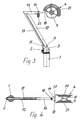
- Fig. 3
- is a lateral view showing the device in another position.
- Fig. 4
- shows, seen from above, the device in the same position as in Figs. 1 and 2.
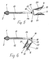
- Fig. 5
- shows the device seen from above, with the puller opened for insertion of a seine.
- Fig. 6
- shows the device seen from above, with the puller pivoted approximately 120° relatively to the position shown in Fig. 4.
- The shown embodiment of the device comprises a
lower column 1, which is mounted in such a manner that it can take up large loads, and the remainder of the device is pivotably mounted on thecolumn 1. Pivotal movement can be achieved with adrive assembly 2, which may for instance be a servo motor having a gear wheel in engagement with a toothed ring. - On the
column 1 is mounted a firstmain arm 12, journalled for pivoting vertically on abracket 3. At the distal end of the main arm 12 a secondmain arm 14 is pivotally mounted, and aparallel arm 13 along themain arm 12 is pivotally mounted on a lowerauxiliary arm 15 and on an extension of the secondmain arm 14, and keeps the secondmain arm 14 horisontal, irrespectively of the position of thearms - In order to cause that an upper line having float elements and a lower line having weight elements along the opposite longitudinal edges of the utensil shall be able to be laid in a regularized manner in a bin, the present device is equipped with a
puller 4 which is movable relatively to the drum on the utensil crane by means of thecolumn 1 and thearms puller 4 is equipped with a pair of rotatable,conical discs discs discs arms puller 4 is moved, but also the drum in the utensil crane, by movement of the pair of arms included in the utensil crane. Consequently, appropriate controlling of the movement of thepuller 4 relatively to the movement of the drum will cause that the upper line having the float elements is laid together in a "bunch" having a desired width on one side of the bin and that the lower line having the weight elements is laid correspondingly together in a "bunch" having a desired width on the opposite side of the bin. - For movement of the
arms cylinder 11 with a piston is in the example shown mounted between thebracket 3 and themain arm 12, and adjusts the position of thearms column 4, bring thepuller 4 to the desired position relatively to the drum. - Moreover, the arm system may be mounted in a movable manner relatively to the fixed mounting of the utensil crane, for instance by means of a rail arrangement (not shown) which also permits pivoting thereof about a mainly vertical pivot axis. It will, however, be appreciated that the arm system alternatively may have a fixed mounting in a suitable distance from the mounting of the utensil crane.
- In order to permit that the
puller 4 may be moved above and catch the upper line and the lower line, respectively, and thereby pull the float elements and the weight elements, respectively, thediscs respective support arm support arms arm 14 by means of a joint 16, whereby thesupport arms cylinder 19 with piston. This implies that thesupport arms arm 14 can be pivoted away from and towards each other. Upon pivoting of thesupport arms discs discs support arms drive device 22, for instance a hydraulic motor, for pivoting the puller as a whole about the end of thearm 14. - The
discs discs discs puller 4 can be reversed, and it may possibly be opened automatically, in order to release the grip around the upper line having the float elements and the lower line having the weight elements, respectively. Thereby, damaging of thepuller 4 or the seine can be avoided. - Alternatively to the embodiment shown also the
main arm 14 may be pivotable in the vertical plane. This may be accomplished by omitting theparallel arm 13 and by mounting a cylinder with piston between themain arms main arm 14 is pivotable or not, themain arm 14 may be extendible, for instance by being telescopic. - The device is suited for operating hydraulically. Hydraulic lines may for instance be inserted in the
column 1, which may contain a swivel coupling for further coupling to the arm system. - The device may be governed by an operator. Moreover, it is possible to control the device as an automatic robot, in that the movements are firstly performed by the operator and are "fed" to a computer for creating a program for controlling and coordinating all the drive assemblies. Thereupon, the device can operate automatically. It is of course possible to create a plurality of programs for such control, for instance for use for different types of fishing utensils, and it is possible to provide feedback to the controlling unit, for instance for correction of movements. Also the utensil crane, if present, can be included in such control and coordination.
Claims (6)
- A device for laying of fishing utensils, in particular for seining, in a utensil bin in a vessel upon hauling, comprising a puller (4) which can be driven in rotation and moved in a horisontal plane and is adapted for pulling of a line in the utensil in the bin, said puller being held by two mutually linked arms (12; 13, 14), a first arm (12) being journalled at one end for pivoting about a vertical axis and able to swing i all vertical planes in which it is placed, while a second arm (14) can swing relatively to the first arm and means (11) are provided for causing these movements of the arms, characterized in that the puller (4) comprises two discs (9, 10) mounted on support arms (17, 18) which are movable relatively to each other in such a manner that there always remains an opening between the discs for free passage of a seine, and that the support arms (17, 18) are movable for controlled pivoting of the puller (4) as a whole about the end of the second arm (14).
- A device as specified in claim 1, wherein the first arm is a double arm, having a main arm (12) and a parallel arm (13) being pivotally journalled with one end and being hinged to an extension of the second arm (14) with the other end.
- A device as specified in claim 1 or 2, wherein the means for driving the arms is a cylinder (11) with piston.
- A device as specified in claim 1, 2 or 3, wherein the support arms (17, 18) are movable relatively to each other by means of a cylinder (19) with piston.
- A device as specified in any of the claims 1 to 4, wherein the discs (9, 10) are equipped with carrier elements adapted to grip around float elements on an upper line and weight elements on a lower line, respectively.
- A device as specified in any of the claims 1 to 5, wherein the arm system (12, 13, 14) for movement of the puller (4) is movably mounted relatively to the base.
Applications Claiming Priority (3)
| Application Number | Priority Date | Filing Date | Title |
|---|---|---|---|
| NO20003000 | 2000-06-09 | ||
| NO20003000A NO311865B1 (en) | 2000-06-09 | 2000-06-09 | Device for laying fishing gear, especially for net fishing, in a gear binge in a vessel after hauling |
| PCT/NO2001/000245 WO2001093670A1 (en) | 2000-06-09 | 2001-06-11 | Device for laying of a fishing utensil, in particular for seining, in a bin |
Publications (3)
| Publication Number | Publication Date |
|---|---|
| EP1292188A1 EP1292188A1 (en) | 2003-03-19 |
| EP1292188B1 true EP1292188B1 (en) | 2006-11-15 |
| EP1292188B9 EP1292188B9 (en) | 2009-03-25 |
Family
ID=19911246
Family Applications (1)
| Application Number | Title | Priority Date | Filing Date |
|---|---|---|---|
| EP01938858A Expired - Lifetime EP1292188B9 (en) | 2000-06-09 | 2001-06-11 | Device for laying of a fishing utensil, in particular for seining, in a bin |
Country Status (8)
| Country | Link |
|---|---|
| EP (1) | EP1292188B9 (en) |
| AT (1) | ATE345038T1 (en) |
| AU (1) | AU2001264434A1 (en) |
| DE (1) | DE60124540D1 (en) |
| ES (1) | ES2275684T3 (en) |
| IS (1) | IS2601B (en) |
| NO (1) | NO311865B1 (en) |
| WO (1) | WO2001093670A1 (en) |
Cited By (1)
| Publication number | Priority date | Publication date | Assignee | Title |
|---|---|---|---|---|
| EP2921049A1 (en) | 2014-03-18 | 2015-09-23 | Etablissements BOPP Treuils JEB | Device for storing a fishing net |
Families Citing this family (10)
| Publication number | Priority date | Publication date | Assignee | Title |
|---|---|---|---|---|
| ES2305441T3 (en) * | 2002-01-25 | 2008-11-01 | Bjorn Halldorsson | PREMONTED NETWORKS IN DOWNLOAD DEVICES AND A MANUFACTURING PROCEDURE. |
| NO320038B1 (en) * | 2003-11-14 | 2005-10-10 | Triplex As | Apparatus, method and an automatic pulling and laying system for a fishing gear |
| ES2288337B1 (en) * | 2004-12-28 | 2008-11-16 | Marine Hydrotec Co., Ltd. | AUXILIARY ROLLER DEVICE FOR NETWORK COLLECTION AND NETWORK COLLECTION METHOD USING THE SAME. |
| ITAN20100113A1 (en) * | 2010-07-05 | 2012-01-06 | Riccardo Giraldi | MOTORIZED DEVICE (ROTARY SHOES) ACTING TO LIFT, RECOVER, PULL OUT OF THE WATER TEXTILE OR SYNTHETIC NETWORKS, FISHING NETS OR VARIOUS TYPE CORDAMES. |
| WO2014054950A1 (en) * | 2012-10-05 | 2014-04-10 | Triplex As | A net crane with corkline layer |
| CN103503842B (en) * | 2013-09-29 | 2015-12-23 | 捷胜海洋装备股份有限公司 | A kind of lifting structure of ball float hauling machine |
| CN103503843B (en) * | 2013-09-29 | 2015-12-02 | 捷胜海洋装备股份有限公司 | A kind of ball float hauling machine |
| JP3194697U (en) | 2014-09-25 | 2014-12-04 | マリンハイドロテック株式会社 | Float processing equipment |
| WO2016134128A1 (en) * | 2015-02-19 | 2016-08-25 | Forever Oceans Corporaton | Automated aquaculture harvesting system |
| NO339359B1 (en) * | 2015-08-25 | 2016-12-05 | Iso Marin As | Device for handling fishing nets |
Family Cites Families (2)
| Publication number | Priority date | Publication date | Assignee | Title |
|---|---|---|---|---|
| US2875547A (en) * | 1958-04-07 | 1959-03-03 | Mario J Puretic | Adjustable and removable support |
| JPH057440A (en) * | 1991-07-02 | 1993-01-19 | Kaiken:Kk | Apparatus for pulling float of round haul net |
-
2000
- 2000-06-09 NO NO20003000A patent/NO311865B1/en not_active IP Right Cessation
-
2001
- 2001-06-11 AU AU2001264434A patent/AU2001264434A1/en not_active Abandoned
- 2001-06-11 AT AT01938858T patent/ATE345038T1/en not_active IP Right Cessation
- 2001-06-11 WO PCT/NO2001/000245 patent/WO2001093670A1/en not_active Ceased
- 2001-06-11 EP EP01938858A patent/EP1292188B9/en not_active Expired - Lifetime
- 2001-06-11 ES ES01938858T patent/ES2275684T3/en not_active Expired - Lifetime
- 2001-06-11 DE DE60124540T patent/DE60124540D1/en not_active Expired - Lifetime
-
2002
- 2002-12-04 IS IS6648A patent/IS2601B/en unknown
Cited By (1)
| Publication number | Priority date | Publication date | Assignee | Title |
|---|---|---|---|---|
| EP2921049A1 (en) | 2014-03-18 | 2015-09-23 | Etablissements BOPP Treuils JEB | Device for storing a fishing net |
Also Published As
| Publication number | Publication date |
|---|---|
| EP1292188B9 (en) | 2009-03-25 |
| NO20003000L (en) | 2001-12-10 |
| WO2001093670A1 (en) | 2001-12-13 |
| ES2275684T3 (en) | 2007-06-16 |
| NO311865B1 (en) | 2002-02-11 |
| NO20003000D0 (en) | 2000-06-09 |
| ATE345038T1 (en) | 2006-12-15 |
| DE60124540D1 (en) | 2006-12-28 |
| EP1292188A1 (en) | 2003-03-19 |
| IS6648A (en) | 2002-12-04 |
| IS2601B (en) | 2010-04-15 |
| AU2001264434A1 (en) | 2001-12-17 |
Similar Documents
| Publication | Publication Date | Title |
|---|---|---|
| EP1292188B9 (en) | Device for laying of a fishing utensil, in particular for seining, in a bin | |
| US5655753A (en) | Ocean bottom cable handling system and method of using same | |
| US5624207A (en) | Ocean bottom cable handling system and method of using same | |
| JPH0213117B2 (en) | ||
| CA2020113C (en) | Tree delimber with tree feeding means | |
| US4414795A (en) | Shaking apparatus | |
| US4714380A (en) | Apparatus to maneuver cables or conduits passing over a direction changer | |
| NO318172B1 (en) | Loading arrangement for loading fluids in an offshore vessel | |
| US5165174A (en) | Harvesting apparatus and method for retrieving subsea traps | |
| CA1317569C (en) | Variable rate boat loader | |
| CN109041867A (en) | Road hedge trimming greening structure and its construction method | |
| KR101834549B1 (en) | Net hauler for fishing vessel | |
| CA2590788A1 (en) | Suspendable tree cutter having an adjustable orientation pivot | |
| EP0061047B1 (en) | Process and device for piling agricultural products, such as roughage and silage in agricultural buildings up to the framework of the roof | |
| WO1997010461A1 (en) | Ocean bottom cable handling system | |
| US4955781A (en) | Variable rate boat loading method | |
| CA1090681A (en) | Method and apparatus for processing trees | |
| TWI635023B (en) | Chain flaker system, to distribute anchor chain evenly in anchor chain locker | |
| US4132025A (en) | Gangion enwrapment control apparatus for long line haulers | |
| JP2005022793A (en) | Winch control device and swing yarder | |
| JPH07155085A (en) | Apparatus for recovering marine product | |
| JPH1014443A (en) | Fish recovering apparatus | |
| CN121734593A (en) | Fishing net collecting and paying device and collecting and paying method for fishing boat | |
| WO2005046324A1 (en) | Device, method and automatic hauling and stowing system for fishing equipment | |
| JPH02167019A (en) | Net lifter in fishing boat |
Legal Events
| Date | Code | Title | Description |
|---|---|---|---|
| PUAI | Public reference made under article 153(3) epc to a published international application that has entered the european phase |
Free format text: ORIGINAL CODE: 0009012 |
|
| 17P | Request for examination filed |
Effective date: 20030106 |
|
| AK | Designated contracting states |
Kind code of ref document: A1 Designated state(s): AT BE CH CY DE DK ES FI FR GB GR IE IT LI LU MC NL PT SE TR Designated state(s): AT BE CH CY DE DK ES FI FR GB GR IE IT LI LU MC NL PT SE TR |
|
| AX | Request for extension of the european patent |
Extension state: AL LT LV MK RO SI |
|
| GRAP | Despatch of communication of intention to grant a patent |
Free format text: ORIGINAL CODE: EPIDOSNIGR1 |
|
| GRAS | Grant fee paid |
Free format text: ORIGINAL CODE: EPIDOSNIGR3 |
|
| RAP1 | Party data changed (applicant data changed or rights of an application transferred) |
Owner name: TRIPLEX AS |
|
| GRAA | (expected) grant |
Free format text: ORIGINAL CODE: 0009210 |
|
| AK | Designated contracting states |
Kind code of ref document: B1 Designated state(s): AT BE CH CY DE DK ES FI FR GB GR IE IT LI LU MC NL PT SE TR |
|
| PG25 | Lapsed in a contracting state [announced via postgrant information from national office to epo] |
Ref country code: IT Free format text: LAPSE BECAUSE OF FAILURE TO SUBMIT A TRANSLATION OF THE DESCRIPTION OR TO PAY THE FEE WITHIN THE PRESCRIBED TIME-LIMIT;WARNING: LAPSES OF ITALIAN PATENTS WITH EFFECTIVE DATE BEFORE 2007 MAY HAVE OCCURRED AT ANY TIME BEFORE 2007. THE CORRECT EFFECTIVE DATE MAY BE DIFFERENT FROM THE ONE RECORDED. Effective date: 20061115 Ref country code: FI Free format text: LAPSE BECAUSE OF FAILURE TO SUBMIT A TRANSLATION OF THE DESCRIPTION OR TO PAY THE FEE WITHIN THE PRESCRIBED TIME-LIMIT Effective date: 20061115 Ref country code: CH Free format text: LAPSE BECAUSE OF FAILURE TO SUBMIT A TRANSLATION OF THE DESCRIPTION OR TO PAY THE FEE WITHIN THE PRESCRIBED TIME-LIMIT Effective date: 20061115 Ref country code: BE Free format text: LAPSE BECAUSE OF FAILURE TO SUBMIT A TRANSLATION OF THE DESCRIPTION OR TO PAY THE FEE WITHIN THE PRESCRIBED TIME-LIMIT Effective date: 20061115 Ref country code: AT Free format text: LAPSE BECAUSE OF FAILURE TO SUBMIT A TRANSLATION OF THE DESCRIPTION OR TO PAY THE FEE WITHIN THE PRESCRIBED TIME-LIMIT Effective date: 20061115 Ref country code: NL Free format text: LAPSE BECAUSE OF FAILURE TO SUBMIT A TRANSLATION OF THE DESCRIPTION OR TO PAY THE FEE WITHIN THE PRESCRIBED TIME-LIMIT Effective date: 20061115 Ref country code: LI Free format text: LAPSE BECAUSE OF FAILURE TO SUBMIT A TRANSLATION OF THE DESCRIPTION OR TO PAY THE FEE WITHIN THE PRESCRIBED TIME-LIMIT Effective date: 20061115 |
|
| REG | Reference to a national code |
Ref country code: GB Ref legal event code: FG4D |
|
| REG | Reference to a national code |
Ref country code: CH Ref legal event code: EP |
|
| REF | Corresponds to: |
Ref document number: 60124540 Country of ref document: DE Date of ref document: 20061228 Kind code of ref document: P |
|
| REG | Reference to a national code |
Ref country code: IE Ref legal event code: FG4D |
|
| PG25 | Lapsed in a contracting state [announced via postgrant information from national office to epo] |
Ref country code: DK Free format text: LAPSE BECAUSE OF FAILURE TO SUBMIT A TRANSLATION OF THE DESCRIPTION OR TO PAY THE FEE WITHIN THE PRESCRIBED TIME-LIMIT Effective date: 20070215 Ref country code: SE Free format text: LAPSE BECAUSE OF FAILURE TO SUBMIT A TRANSLATION OF THE DESCRIPTION OR TO PAY THE FEE WITHIN THE PRESCRIBED TIME-LIMIT Effective date: 20070215 |
|
| PG25 | Lapsed in a contracting state [announced via postgrant information from national office to epo] |
Ref country code: DE Free format text: LAPSE BECAUSE OF FAILURE TO SUBMIT A TRANSLATION OF THE DESCRIPTION OR TO PAY THE FEE WITHIN THE PRESCRIBED TIME-LIMIT Effective date: 20070216 |
|
| ET | Fr: translation filed | ||
| PG25 | Lapsed in a contracting state [announced via postgrant information from national office to epo] |
Ref country code: PT Free format text: LAPSE BECAUSE OF FAILURE TO SUBMIT A TRANSLATION OF THE DESCRIPTION OR TO PAY THE FEE WITHIN THE PRESCRIBED TIME-LIMIT Effective date: 20070416 |
|
| NLV1 | Nl: lapsed or annulled due to failure to fulfill the requirements of art. 29p and 29m of the patents act | ||
| REG | Reference to a national code |
Ref country code: CH Ref legal event code: PL |
|
| REG | Reference to a national code |
Ref country code: ES Ref legal event code: FG2A Ref document number: 2275684 Country of ref document: ES Kind code of ref document: T3 |
|
| PLBE | No opposition filed within time limit |
Free format text: ORIGINAL CODE: 0009261 |
|
| STAA | Information on the status of an ep patent application or granted ep patent |
Free format text: STATUS: NO OPPOSITION FILED WITHIN TIME LIMIT |
|
| 26N | No opposition filed |
Effective date: 20070817 |
|
| PG25 | Lapsed in a contracting state [announced via postgrant information from national office to epo] |
Ref country code: MC Free format text: LAPSE BECAUSE OF NON-PAYMENT OF DUE FEES Effective date: 20070630 |
|
| GBPC | Gb: european patent ceased through non-payment of renewal fee |
Effective date: 20070611 |
|
| PG25 | Lapsed in a contracting state [announced via postgrant information from national office to epo] |
Ref country code: GR Free format text: LAPSE BECAUSE OF FAILURE TO SUBMIT A TRANSLATION OF THE DESCRIPTION OR TO PAY THE FEE WITHIN THE PRESCRIBED TIME-LIMIT Effective date: 20070216 |
|
| PG25 | Lapsed in a contracting state [announced via postgrant information from national office to epo] |
Ref country code: GB Free format text: LAPSE BECAUSE OF NON-PAYMENT OF DUE FEES Effective date: 20070611 Ref country code: IE Free format text: LAPSE BECAUSE OF NON-PAYMENT OF DUE FEES Effective date: 20070611 |
|
| PG25 | Lapsed in a contracting state [announced via postgrant information from national office to epo] |
Ref country code: CY Free format text: LAPSE BECAUSE OF FAILURE TO SUBMIT A TRANSLATION OF THE DESCRIPTION OR TO PAY THE FEE WITHIN THE PRESCRIBED TIME-LIMIT Effective date: 20061115 Ref country code: LU Free format text: LAPSE BECAUSE OF NON-PAYMENT OF DUE FEES Effective date: 20070611 |
|
| PG25 | Lapsed in a contracting state [announced via postgrant information from national office to epo] |
Ref country code: TR Free format text: LAPSE BECAUSE OF FAILURE TO SUBMIT A TRANSLATION OF THE DESCRIPTION OR TO PAY THE FEE WITHIN THE PRESCRIBED TIME-LIMIT Effective date: 20061115 |
|
| REG | Reference to a national code |
Ref country code: FR Ref legal event code: PLFP Year of fee payment: 16 |
|
| REG | Reference to a national code |
Ref country code: FR Ref legal event code: PLFP Year of fee payment: 17 |
|
| REG | Reference to a national code |
Ref country code: FR Ref legal event code: PLFP Year of fee payment: 18 |
|
| PGFP | Annual fee paid to national office [announced via postgrant information from national office to epo] |
Ref country code: FR Payment date: 20200619 Year of fee payment: 20 |
|
| PGFP | Annual fee paid to national office [announced via postgrant information from national office to epo] |
Ref country code: ES Payment date: 20200824 Year of fee payment: 20 |
|
| REG | Reference to a national code |
Ref country code: ES Ref legal event code: FD2A Effective date: 20211029 |
|
| PG25 | Lapsed in a contracting state [announced via postgrant information from national office to epo] |
Ref country code: ES Free format text: LAPSE BECAUSE OF EXPIRATION OF PROTECTION Effective date: 20210612 |