EP1295662A1 - Säge mit hin- und hergehendem bündig angeordnetem Sägeblatt - Google Patents
Säge mit hin- und hergehendem bündig angeordnetem Sägeblatt Download PDFInfo
- Publication number
- EP1295662A1 EP1295662A1 EP02256519A EP02256519A EP1295662A1 EP 1295662 A1 EP1295662 A1 EP 1295662A1 EP 02256519 A EP02256519 A EP 02256519A EP 02256519 A EP02256519 A EP 02256519A EP 1295662 A1 EP1295662 A1 EP 1295662A1
- Authority
- EP
- European Patent Office
- Prior art keywords
- wobble
- saw
- housing
- plane
- axis
- Prior art date
- Legal status (The legal status is an assumption and is not a legal conclusion. Google has not performed a legal analysis and makes no representation as to the accuracy of the status listed.)
- Withdrawn
Links
Images


Classifications
-
- B—PERFORMING OPERATIONS; TRANSPORTING
- B23—MACHINE TOOLS; METAL-WORKING NOT OTHERWISE PROVIDED FOR
- B23D—PLANING; SLOTTING; SHEARING; BROACHING; SAWING; FILING; SCRAPING; LIKE OPERATIONS FOR WORKING METAL BY REMOVING MATERIAL, NOT OTHERWISE PROVIDED FOR
- B23D49/00—Machines or devices for sawing with straight reciprocating saw blades, e.g. hacksaws
- B23D49/10—Hand-held or hand-operated sawing devices with straight saw blades
- B23D49/11—Hand-held or hand-operated sawing devices with straight saw blades for special purposes, e.g. offset-blade hand; Hand saws having spaced blades; Hand saws for sawing grooves or square holes
-
- B—PERFORMING OPERATIONS; TRANSPORTING
- B23—MACHINE TOOLS; METAL-WORKING NOT OTHERWISE PROVIDED FOR
- B23D—PLANING; SLOTTING; SHEARING; BROACHING; SAWING; FILING; SCRAPING; LIKE OPERATIONS FOR WORKING METAL BY REMOVING MATERIAL, NOT OTHERWISE PROVIDED FOR
- B23D49/00—Machines or devices for sawing with straight reciprocating saw blades, e.g. hacksaws
- B23D49/10—Hand-held or hand-operated sawing devices with straight saw blades
- B23D49/16—Hand-held or hand-operated sawing devices with straight saw blades actuated by electric or magnetic power or prime movers
- B23D49/162—Pad sawing devices
- B23D49/167—Pad sawing devices with means to adjust the guide plate or with means to adjust the plane in which the saw blade moves
-
- B—PERFORMING OPERATIONS; TRANSPORTING
- B23—MACHINE TOOLS; METAL-WORKING NOT OTHERWISE PROVIDED FOR
- B23D—PLANING; SLOTTING; SHEARING; BROACHING; SAWING; FILING; SCRAPING; LIKE OPERATIONS FOR WORKING METAL BY REMOVING MATERIAL, NOT OTHERWISE PROVIDED FOR
- B23D51/00—Sawing machines or sawing devices working with straight blades, characterised only by constructional features of particular parts; Carrying or attaching means for tools, covered by this subclass, which are connected to a carrier at both ends
- B23D51/08—Sawing machines or sawing devices working with straight blades, characterised only by constructional features of particular parts; Carrying or attaching means for tools, covered by this subclass, which are connected to a carrier at both ends of devices for mounting straight saw blades or other tools
- B23D51/10—Sawing machines or sawing devices working with straight blades, characterised only by constructional features of particular parts; Carrying or attaching means for tools, covered by this subclass, which are connected to a carrier at both ends of devices for mounting straight saw blades or other tools for hand-held or hand-operated devices
-
- B—PERFORMING OPERATIONS; TRANSPORTING
- B23—MACHINE TOOLS; METAL-WORKING NOT OTHERWISE PROVIDED FOR
- B23D—PLANING; SLOTTING; SHEARING; BROACHING; SAWING; FILING; SCRAPING; LIKE OPERATIONS FOR WORKING METAL BY REMOVING MATERIAL, NOT OTHERWISE PROVIDED FOR
- B23D51/00—Sawing machines or sawing devices working with straight blades, characterised only by constructional features of particular parts; Carrying or attaching means for tools, covered by this subclass, which are connected to a carrier at both ends
- B23D51/16—Sawing machines or sawing devices working with straight blades, characterised only by constructional features of particular parts; Carrying or attaching means for tools, covered by this subclass, which are connected to a carrier at both ends of drives or feed mechanisms for straight tools, e.g. saw blades, or bows
- B23D51/161—Sawing machines or sawing devices working with straight blades, characterised only by constructional features of particular parts; Carrying or attaching means for tools, covered by this subclass, which are connected to a carrier at both ends of drives or feed mechanisms for straight tools, e.g. saw blades, or bows with dynamic balancing
Definitions
- the invention relates to portable power tools featuring a reciprocating, cantilevered saw blade.
- the saw blade of such known reciprocating saws is mounted on a saw bar that is nominally centered within the housing, such that the saw bar reciprocates in a vertical plane that includes the longitudinal axis of the housing.
- such known reciprocating saws typically employ saw blades that resiliently bend or flex in a plane normal to the blade's nominal (typically vertical) cutting plane. In this manner, for example, a saw cut can conveniently be made along an edge defined by the intersection of two generally planar surfaces by holding the saw proximate to one surface adjacent the corner and flexing the saw blade flush with the one surface.
- the prior art teaches use of a blade holder or adapter on a reciprocating saw that allows the user to laterally offset the saw blade such that the nominal (vertical) cutting plane of the blade is moved toward a side surface of the saw housing.
- Another known saw bar/blade adapter vertically offsets the blade axis from the saw bar axis while further permitting the blade to be mounted horizontally relative to the housing, such that the blade's cutting plane is roughly tangential to the upper surface of the housing.
- known blade holders/adapters continue to center the offset blade either vertically or horizontally on the housing, in part because such known reciprocating saws often employ counterweighted drive assemblies that require a geometrically-centered saw bar in order to optimize the performance of certain oppositely-reciprocating counterweights in reducing tool vibration during use.
- known reciprocating saws often employ an annular or U-shaped counterweight that is reciprocated about the same longitudinal axis as the saw bar, thereby requiring relatively central positioning of the saw bar axis within the housing.
- the cutting edge of the offset blade is likewise roughly centered with respect to a vertical or horizontal dimension of the housing, thereby rendering more difficult cuts, for example, into corners defined by the intersection of three generally planar surfaces, and similarly implicating significant surface preparation to avoid unintended damage to adjacent surfaces.
- a reciprocating saw preferably with a geometrically-simplified drive assembly, that allows a user to perform edge- and corner-cutting operations without extensive preparation to the surface and with minimal flexing of the saw blade.
- Another object of the invention is to provide a compact reciprocating saw featuring ease of maneuverability while cutting.
- a further object of the invention is to provide a geometrically-simplified drive mechanism for a reciprocating saw which facilitates placement of the saw bar axis at a relative outboard position on the saw housing.
- a reciprocating saw includes a housing having an upper surface and a side surface defined, for example, on a nose portion at a longitudinal end of the housing.
- a blade holder is mounted, for example, on the end of a projecting saw bar that is itself supported for reciprocating motion on the housing.
- the blade holder is adapted to support a thin saw blade having a cutting edge for reciprocation along a blade holder axis within a cutting plane. such that the cutting plane does not intersect one of the upper and side surfaces of the housing, the blade holder being further adapted to support the saw blade such that a reference plane that is orthogonal to the cutting plane and that intersects the cutting edge does not intersect the other of the upper and side surfaces of the housing.
- the housing includes at least one flat that is either generally parallel to, or is disposed at a nonzero angle with respect to, the cutting plane or the reference plane.
- the blade holder is preferably adapted to support the saw blade such that the blade's cutting edge is proximate to an intersection of the planar extensions of such flats.
- the blade holder is preferably adapted to support the saw blade in a plurality of orientations on a plurality of mounting locations defined on the blade holder. In an exemplary embodiment, the mounting locations of the blade holder are separated by an included angle of about 90 degrees.
- an exemplary reciprocating saw includes a wobble drive assembly that employs a single wobble plate having an integrated counterweight to thereby simplify the saw bar drive mechanism while further facilitating outboard placement of the saw bar (and associated blade holder axis) relative to the saw's housing.
- the wobble drive assembly has a single wobble plate that is mounted in the housing for rotation about a first wobble axis that is generally parallel to the blade holder axis.
- the wobble drive assembly includes a wobble plate rotatable about a second wobble axis that is canted with respect to the first wobble axis.
- the wobble plate has a driving end located at a radial distance from the second wobble axis that is coupled to the saw bar and is constrained to move within a wobble plane which includes the first wobble axis. Rotation of the wobble plate about the first wobble axis causes the driving end of the wobble plate to impart a reciprocating motion to the saw bar.
- the wobble plate includes a counterweight such that the wobble plate is inertially balanced about an inertial axis extending in a direction normal to the wobble plane that intersects the wobble plane proximate to the second wobble axis.
- the wobble plane of the exemplary wobble drive assembly is canted with respect to one of the reference planes and is disposed at an acute nonzero angle with respect to the cutting plane defined by a nonflexed saw blade supported by the blade holder.
- an exemplary reciprocating saw in accordance with the invention beneficially features a reduced housing profile in cross-section, thereby further improving tool maneuverability and further minimizing unintended damage to adjacent surfaces during edge- and corner-cutting operations.
- an exemplary, hand-held reciprocating saw 10 in accordance with the invention includes a housing 12 having a handle 14 defined proximate to one end 16, and a tapered nose portion 18 defined proximate to the other end 20.
- the handle 14 includes a trigger switch 22 by which to control an electric motor (not shown) fixed within the housing 12.
- the nose portion 18 is provided with an exterior shape which allows a user to grip the nose portion 18 during use. While the housing 12 is formed of any suitable material, in the exemplary saw 10, the housing 12 is formed of injection-molded plastic halves that are secured together in a clam shell manner.
- the exemplary saw 10 includes a saw bar 24 that projects from the nose portion 18 of the housing 12 along a longitudinal axis 26 of the housing 12.
- a blade holder 28 on the free end of the saw bar 24 is adapted to support a saw blade 30 in each of two blade orientations, as discussed further below, for reciprocation along a blade holder axis 32 that, in the exemplary saw 10, is also generally aligned with the longitudinal axis 26 of the saw bar 24.
- a shoe mount 34 also extends from the nose portion 18 of the housing 12. The shoe mount 34 is adapted to receive a shoe 36 that may be abutted against a workpiece during a cutting operation to help guide the saw 10 along the workpiece.
- the blade holder 28 on the end of the saw bar 24 is adapted to support the unloaded or nonflexed saw blade 30 in such a way as to define a respective cutting plane 38a,38b, for each orientation of the blade 30 on the blade holder 28, that does not intersect the housing 12.
- the blade holder 28 is adapted to support the saw blade 30 such that a reference plane 40a,40b orthogonal to the cutting plane 38a,38b and intersecting a cutting edge 42a,42b defined on the saw blade 30 likewise does not intersect the outer surface of the nose portion 18 of the housing 12.
- the exemplary saw 10 allows a user to easily make continuous saw cuts in "hard to reach" locations with minimal bending to the saw blade 30, thereby greatly reducing the likelihood of unintended damage to either the adjacent surfaces of the workpiece or to the saw 10.
- the cutting plane 38a,38b and reference plane 40a,40b preferably lie proximate to, and are only slightly offset from, a respective side and top surface of the housing 12. And, as seen in Figures 3 and 8, the cutting planes 38a,38b and reference planes 40a,40b may also lie either generally parallel to, or at a nominal angle with respect to, a respective flat 44,46 defined on the housing's nose portion 18.
- the blade holder 28 is adapted to support the saw blade 30 with the blade's cutting edge 42a,42b proximate to the nominal intersection 48 of a respective planar extension of such flats 44,46.
- the blade holder 28 includes a pair of mounting locations 50,52 that are roughly disposed at a right angle to one another, when viewed in cross-section along the blade holder axis 32.
- each of the mounting locations 50,52 is preferably adapted to support the saw blade 30 with the blade's cutting edge 42a,42b in either of two diametrical positions, to thereby provide the exemplary saw 10 with even greater flexibility in use.
- the exemplary saw 10 includes a pinion gear 60 that is suitably coupled for rotation with the armature shaft 62 of the electric motor.
- the pinion gear 60 drives a reducing gear 64 that is mounted on an intermediate shaft 66 for rotation about a first axis 68 that is conveniently a longitudinal axis of the housing 12 and, hence, is generally parallel to the blade holder axis 32.
- a wobble drive assembly 70 is also mounted on the intermediate shaft 66.
- the wobble drive assembly 70 includes a wobble shaft 72 that is coupled to the reducing gear 64 for rotation about the first axis 68.
- the wobble shaft 72 defines a second axis 74 which is canted with respect to the first axis 68 and which rotates about the first axis 68.
- the wobble drive assembly 70 further includes a single wobble plate 76 rotatably supported about the wobble shaft 72 and rotatable about the second axis 74.
- the wobble plate 76 has a ball-shaped driving end 78 located at a radial distance from the second wobble axis 74.
- the driving end 78 of the wobble plate 76 is received in a complementary socket 80 defined in the saw bar 24 (as best seen in Figure 6).
- the driving end 78 of the wobble plate 76 is constrained to move within a wobble plane 82 which includes the first wobble axis 68.
- the wobble plane 82 is best illustrated in Figure 3.
- the driving end 78 of the wobble plate 76 oscillates within the wobble plane 82 to thereby impart reciprocating motion to the saw bar 24, the blade holder 28 and the supported saw blade 30.
- a counterweight 84 is defined on the wobble plate 76 opposite to the driving end 78.
- the counterweight 84 inertially balances the wobble plate 76 about an inertial axis 86 that intersects the wobble plane 82 proximate to the second axis 74.
- the inertial axis 86 is likewise best seen in Figure 3.
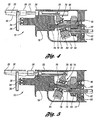
- Figures 4 and 5 respectively illustrate the counterweight 84 in the rearmost and foremost positions, when the saw bar 24 is respectively in the fully-extended and fully-retracted positions.
- the counterweight 84 is secured to the wobble plate 76 with a pair of threaded fasteners.
- the use of the single, counterbalanced wobble plate 76 in the wobble drive assembly 70 advantageously provides a more compact drive mechanism for the exemplary saw 10, at relatively lower cost, with the further benefit that the resulting saw 10 has improved maneuverability over known reciprocating saw designs.
- the saw bar 24 is illustrated cooperating with the driving end 78 of the wobble plate 76.
- the saw bar 24 is thin and rectangular in cross section, in contrast with conventional saw bars of generally-square or -circular cross section.
- the thin saw bar 24 advantageously has a lower mass than the conventional designs, so that less mass is required by the counterweight 84.
- a linear bearing 90 in the housing 12 slidably receives the saw bar 24 for reciprocating motion and, further, provides transverse support for the saw bar 24.
- the bearing 90 includes a channel providing clearance for the driving end 78 of the wobble plate 76 as it imparts the reciprocating motion to the saw bar 24.
- the bearing 90 is conveniently formed of powder metal that is preferably self-lubricating to thereby reduce friction against the saw bar 24.
- the wobble drive assembly 70 is illustrated in further detail in Figure 7. While the invention contemplates supporting the wobble plate 76 on the wobble shaft 72 for rotation in any suitable manner, in the exemplary saw 10, the wobble plate 76 is rotatably supported about the wobble shaft 72 by a pair of adjacent ball bearing assemblies 92 for reduced friction.
- the bearing assemblies 92 are spaced apart by an annular spacer 94 and retained about the wobble shaft 72 by a retaining ring 96.
- the wobble plate 76 is retained and axially loaded about the bearing assemblies 92 by a wave spring 98.
- the bearing assemblies 92 are fixed within the wobble plate 76 using a suitable adhesive delivered through appropriate passages 100 defined in the wobble plate.
- the invention provides a relatively low-cost solution that overcomes the deficiencies of known reciprocating saws with respect to edge- and corner-cutting operations.
Landscapes
- Engineering & Computer Science (AREA)
- Mechanical Engineering (AREA)
- Sawing (AREA)
Applications Claiming Priority (2)
| Application Number | Priority Date | Filing Date | Title |
|---|---|---|---|
| US09/961,497 US20030051352A1 (en) | 2001-09-20 | 2001-09-20 | Reciprocating saw with flush blade |
| US961497 | 2001-09-20 |
Publications (1)
| Publication Number | Publication Date |
|---|---|
| EP1295662A1 true EP1295662A1 (de) | 2003-03-26 |
Family
ID=25504547
Family Applications (1)
| Application Number | Title | Priority Date | Filing Date |
|---|---|---|---|
| EP02256519A Withdrawn EP1295662A1 (de) | 2001-09-20 | 2002-09-20 | Säge mit hin- und hergehendem bündig angeordnetem Sägeblatt |
Country Status (4)
| Country | Link |
|---|---|
| US (1) | US20030051352A1 (de) |
| EP (1) | EP1295662A1 (de) |
| JP (1) | JP2003159615A (de) |
| CA (1) | CA2394395A1 (de) |
Cited By (6)
| Publication number | Priority date | Publication date | Assignee | Title |
|---|---|---|---|---|
| US6944959B2 (en) | 1995-06-09 | 2005-09-20 | Black & Decker Inc. | Clamping arrangement for receiving a saw blade in multiple orientations |
| GB2415661A (en) * | 2004-05-28 | 2006-01-04 | Bosch Gmbh Robert | An anti-rotation mechanism for a reciprocating saw |
| EP1818141A3 (de) * | 2003-03-21 | 2007-11-28 | Black & Decker, Inc. | Schwingungsreduziervorrichtung für kraftbetriebenes Werkzeug und solch eine Vorrichtung enthaltendes kraftbetriebenes Werkzeug |
| US7325315B2 (en) | 1995-06-09 | 2008-02-05 | Black & Decker Inc. | Clamping arrangement for receiving a saw blade in multiple orientations |
| EP2374565A3 (de) * | 2010-04-07 | 2011-11-16 | Robert Bosch Gmbh | Antriebsmechanismus für ein hin- und hergehendes Werkzeug |
| EP2025440A3 (de) * | 2007-08-17 | 2012-07-11 | Festool GmbH | Vorsatzgerät für eine Hubsäge |
Families Citing this family (21)
| Publication number | Priority date | Publication date | Assignee | Title |
|---|---|---|---|---|
| USD504603S1 (en) * | 2002-09-04 | 2005-05-03 | Positec Power Tools (Suzhou) Co. Ltd. | Reciprocating saw |
| USD506117S1 (en) * | 2003-07-19 | 2005-06-14 | Credo Technology Corporation | Reciprocating saw |
| JP4405195B2 (ja) | 2003-08-01 | 2010-01-27 | 株式会社マキタ | 往復動式電動工具 |
| WO2005068121A1 (en) * | 2004-01-06 | 2005-07-28 | Ritter Jon S | Flush cut adapter |
| DE102004022361B4 (de) * | 2004-05-06 | 2007-06-06 | Hilti Ag | Hubsägewerkzeug |
| DE102006031513A1 (de) * | 2006-07-07 | 2008-01-17 | Robert Bosch Gmbh | Handwerkzeugmaschine, insbesondere Handsäge |
| US7797841B2 (en) * | 2006-08-29 | 2010-09-21 | Robert Bosch Gmbh | Drive mechanism for a reciprocating saw |
| US7707729B2 (en) * | 2007-02-02 | 2010-05-04 | Robert Bosch Gmbh | Drive mechanism for a reciprocating tool |
| US8549762B2 (en) * | 2007-02-13 | 2013-10-08 | Robert Bosch Gmbh | Linkage drive mechanism for a reciprocating tool |
| US7814666B2 (en) * | 2007-02-13 | 2010-10-19 | Robert Bosch Gmbh | Linkage drive mechanism for a reciprocating tool |
| US8230607B2 (en) | 2008-05-09 | 2012-07-31 | Milwaukee Electric Tool Corporation | Keyless blade clamp for a power tool |
| AU2012202705B8 (en) | 2011-03-07 | 2014-11-06 | Infusion Brands, Inc. | Dual blade reciprocating saw |
| DE102013212554B4 (de) * | 2013-06-28 | 2023-12-14 | Robert Bosch Gmbh | Handwerkzeugmaschinenantriebsvorrichtung |
| CN203471741U (zh) * | 2013-09-13 | 2014-03-12 | 王国雄 | 电钻转接头 |
| EP3083172A1 (de) * | 2013-12-20 | 2016-10-26 | Robert Bosch GmbH | Oszillierender mechanismus für ein elektrowerkzeug |
| US10654188B2 (en) * | 2014-12-31 | 2020-05-19 | Robert Bosch Tool Corporation | Guide foot for an oscillating cutting tool |
| CN107900451A (zh) * | 2017-12-22 | 2018-04-13 | 合保电气(芜湖)有限公司 | 电力作业锯 |
| USD901273S1 (en) * | 2018-04-25 | 2020-11-10 | Black & Decker Inc. | Reciprocating saw |
| USD964134S1 (en) * | 2018-09-07 | 2022-09-20 | Jeremy Leman | Reciprocating saw |
| CN112970451B (zh) * | 2019-12-02 | 2024-01-30 | 创科无线普通合伙 | 一种电动修枝机 |
| CN115889892B (zh) * | 2021-09-30 | 2025-03-14 | 南京泉峰科技有限公司 | 往复锯 |
Citations (12)
| Publication number | Priority date | Publication date | Assignee | Title |
|---|---|---|---|---|
| US2824455A (en) * | 1952-06-27 | 1958-02-25 | Milwaukee Electric Tool Corp | Portable reciprocating saw |
| US4553306A (en) * | 1983-11-07 | 1985-11-19 | Mineck Paul S | Reciprocating saw offset blade holder |
| US4566190A (en) * | 1983-08-22 | 1986-01-28 | Isakson Stig A | Reciprocating blade cutting device |
| US4876793A (en) * | 1988-06-27 | 1989-10-31 | Quaglia James A | Jamb saw |
| DE4415848A1 (de) * | 1994-05-05 | 1995-11-09 | Festo Tooltechnic Kg | Motorisch angetriebene Handsäge |
| US5555626A (en) * | 1995-11-27 | 1996-09-17 | S-B Power Tool Company | Reciprocating drive mechanism |
| EP0768138A2 (de) * | 1995-10-10 | 1997-04-16 | Black & Decker Inc. | Sägemaschine mit hin- und hergehendem Sägeblatt und drehbarer Sägeblatthalterung |
| US5809657A (en) * | 1997-04-18 | 1998-09-22 | Mortensen; Frank | Power saw blade adaptor |
| DE19756765A1 (de) * | 1997-12-19 | 1999-06-24 | Bosch Gmbh Robert | Elektrische Handsägemaschine |
| WO1999032249A1 (de) * | 1997-12-19 | 1999-07-01 | Robert Bosch Gmbh | Elektrische handwerkzeugmaschine |
| GB2340441A (en) * | 1998-08-14 | 2000-02-23 | Bosch Gmbh Robert | Eccentric for a hand held machine tool |
| GB2345461A (en) * | 1998-11-09 | 2000-07-12 | Bosch Gmbh Robert | Reciprocating saw blade provided with abrasive for scribing a workpiece |
Family Cites Families (2)
| Publication number | Priority date | Publication date | Assignee | Title |
|---|---|---|---|---|
| US3155128A (en) * | 1961-09-29 | 1964-11-03 | Stanley Works | Portable reciprocating saw |
| US3260290A (en) * | 1964-04-16 | 1966-07-12 | Singer Co | Attachment for sabre saw for flush cutting and side cutting |
-
2001
- 2001-09-20 US US09/961,497 patent/US20030051352A1/en not_active Abandoned
-
2002
- 2002-07-22 CA CA002394395A patent/CA2394395A1/en not_active Abandoned
- 2002-09-20 JP JP2002275437A patent/JP2003159615A/ja active Pending
- 2002-09-20 EP EP02256519A patent/EP1295662A1/de not_active Withdrawn
Patent Citations (12)
| Publication number | Priority date | Publication date | Assignee | Title |
|---|---|---|---|---|
| US2824455A (en) * | 1952-06-27 | 1958-02-25 | Milwaukee Electric Tool Corp | Portable reciprocating saw |
| US4566190A (en) * | 1983-08-22 | 1986-01-28 | Isakson Stig A | Reciprocating blade cutting device |
| US4553306A (en) * | 1983-11-07 | 1985-11-19 | Mineck Paul S | Reciprocating saw offset blade holder |
| US4876793A (en) * | 1988-06-27 | 1989-10-31 | Quaglia James A | Jamb saw |
| DE4415848A1 (de) * | 1994-05-05 | 1995-11-09 | Festo Tooltechnic Kg | Motorisch angetriebene Handsäge |
| EP0768138A2 (de) * | 1995-10-10 | 1997-04-16 | Black & Decker Inc. | Sägemaschine mit hin- und hergehendem Sägeblatt und drehbarer Sägeblatthalterung |
| US5555626A (en) * | 1995-11-27 | 1996-09-17 | S-B Power Tool Company | Reciprocating drive mechanism |
| US5809657A (en) * | 1997-04-18 | 1998-09-22 | Mortensen; Frank | Power saw blade adaptor |
| DE19756765A1 (de) * | 1997-12-19 | 1999-06-24 | Bosch Gmbh Robert | Elektrische Handsägemaschine |
| WO1999032249A1 (de) * | 1997-12-19 | 1999-07-01 | Robert Bosch Gmbh | Elektrische handwerkzeugmaschine |
| GB2340441A (en) * | 1998-08-14 | 2000-02-23 | Bosch Gmbh Robert | Eccentric for a hand held machine tool |
| GB2345461A (en) * | 1998-11-09 | 2000-07-12 | Bosch Gmbh Robert | Reciprocating saw blade provided with abrasive for scribing a workpiece |
Cited By (15)
| Publication number | Priority date | Publication date | Assignee | Title |
|---|---|---|---|---|
| US7325315B2 (en) | 1995-06-09 | 2008-02-05 | Black & Decker Inc. | Clamping arrangement for receiving a saw blade in multiple orientations |
| US8046926B2 (en) | 1995-06-09 | 2011-11-01 | Black & Decker Inc. | Clamping arrangement for receiving a saw blade in multiple orientations |
| US7003888B2 (en) | 1995-06-09 | 2006-02-28 | Black & Decker Inc. | Clamping arrangement for receiving a saw blade |
| US6944959B2 (en) | 1995-06-09 | 2005-09-20 | Black & Decker Inc. | Clamping arrangement for receiving a saw blade in multiple orientations |
| US7562721B2 (en) | 2003-03-21 | 2009-07-21 | Black & Decker Inc. | Vibration reduction apparatus for power tool and power tool incorporating such apparatus |
| EP1818141A3 (de) * | 2003-03-21 | 2007-11-28 | Black & Decker, Inc. | Schwingungsreduziervorrichtung für kraftbetriebenes Werkzeug und solch eine Vorrichtung enthaltendes kraftbetriebenes Werkzeug |
| US7445056B2 (en) | 2003-03-21 | 2008-11-04 | Black & Decker Inc. | Vibration reduction apparatus for power tool and power tool incorporating such apparatus |
| US7533736B2 (en) | 2003-03-21 | 2009-05-19 | Black & Decker Inc. | Vibration reduction apparatus for power tool and power tool incorporating such apparatus |
| US7168169B2 (en) | 2004-05-28 | 2007-01-30 | Robert Bosch Gmbh | Anti-rotation drive mechanism for a reciprocating saw |
| GB2415661B (en) * | 2004-05-28 | 2006-06-07 | Bosch Gmbh Robert | Anti-rotation mechanism for a reciprocating saw |
| GB2415661A (en) * | 2004-05-28 | 2006-01-04 | Bosch Gmbh Robert | An anti-rotation mechanism for a reciprocating saw |
| EP2025440A3 (de) * | 2007-08-17 | 2012-07-11 | Festool GmbH | Vorsatzgerät für eine Hubsäge |
| EP2374565A3 (de) * | 2010-04-07 | 2011-11-16 | Robert Bosch Gmbh | Antriebsmechanismus für ein hin- und hergehendes Werkzeug |
| US8307910B2 (en) | 2010-04-07 | 2012-11-13 | Robert Bosch Gmbh | Drive mechanism for a reciprocating tool |
| US9272347B2 (en) | 2010-04-07 | 2016-03-01 | Robert Bosch Gmbh | Drive mechanism for a reciprocating tool |
Also Published As
| Publication number | Publication date |
|---|---|
| CA2394395A1 (en) | 2003-03-20 |
| US20030051352A1 (en) | 2003-03-20 |
| JP2003159615A (ja) | 2003-06-03 |
Similar Documents
| Publication | Publication Date | Title |
|---|---|---|
| EP1295662A1 (de) | Säge mit hin- und hergehendem bündig angeordnetem Sägeblatt | |
| US6568089B1 (en) | Reciprocating saw having compact configuration and independent stability | |
| EP2374565B1 (de) | Antriebsmechanismus für ein hin- und hergehendes Werkzeug | |
| EP3568253B1 (de) | Säge mit hin und her gehendem sägeblatt | |
| US5079844A (en) | Counterbalanced reciprocating mechanism | |
| US7191847B2 (en) | Drive for a motor-driven hand-held tool | |
| EP2785485B1 (de) | Gelenkige hubsägemaschine | |
| US3802079A (en) | Saw blade holder for portable reciprocating saw | |
| EP0561473B1 (de) | Pendelhubantrieb mit Ausgleichgewicht für Sägen oder dergleichen | |
| US10300541B2 (en) | Reciprocating saw | |
| CN106466862A (zh) | 作业工具 | |
| CN114131565A (zh) | 动力工具 | |
| EP2374564B1 (de) | Hin- und hergehende Schneidwerkzeuge | |
| US20180370012A1 (en) | Electric Power Tool | |
| GB2441401A (en) | Reciprocating drive apparatus | |
| JPH0630339Y2 (ja) | 往復動工具 | |
| US6694625B1 (en) | Power tool | |
| US10272506B2 (en) | Reciprocating tool with linear guides | |
| JP3897653B2 (ja) | 往復動式電動工具 | |
| NZ529972A (en) | Reciprocating saw with flush blade, and wobble drive with counterweight to reduce blade bending | |
| US11759873B2 (en) | Reciprocating saw | |
| CN118559815A (zh) | 切割装置 | |
| EP1514655B1 (de) | Fussplattenanordnung für für hin- und hergehendes Werkzeug | |
| US12194552B2 (en) | Tool accessory mounting interface | |
| CN110962082A (zh) | 多功能机 |
Legal Events
| Date | Code | Title | Description |
|---|---|---|---|
| PUAI | Public reference made under article 153(3) epc to a published international application that has entered the european phase |
Free format text: ORIGINAL CODE: 0009012 |
|
| AK | Designated contracting states |
Kind code of ref document: A1 Designated state(s): AT BE BG CH CY CZ DE DK EE ES FI FR GB GR IE IT LI LU MC NL PT SE SK TR Designated state(s): AT BE BG CH CY CZ DE DK EE ES FI FR GB GR IE IT LI LU MC NL PT SE SK TR |
|
| AX | Request for extension of the european patent |
Extension state: AL LT LV MK RO SI |
|
| 17P | Request for examination filed |
Effective date: 20030512 |
|
| AKX | Designation fees paid |
Designated state(s): DE FR GB |
|
| STAA | Information on the status of an ep patent application or granted ep patent |
Free format text: STATUS: THE APPLICATION IS DEEMED TO BE WITHDRAWN |
|
| 18D | Application deemed to be withdrawn |
Effective date: 20060920 |