EP1297951A2 - Cylindre porte-plaque en trois parties avec des ajustements latéraux et circulaires pour l'enregistrement - Google Patents
Cylindre porte-plaque en trois parties avec des ajustements latéraux et circulaires pour l'enregistrement Download PDFInfo
- Publication number
- EP1297951A2 EP1297951A2 EP02021095A EP02021095A EP1297951A2 EP 1297951 A2 EP1297951 A2 EP 1297951A2 EP 02021095 A EP02021095 A EP 02021095A EP 02021095 A EP02021095 A EP 02021095A EP 1297951 A2 EP1297951 A2 EP 1297951A2
- Authority
- EP
- European Patent Office
- Prior art keywords
- plate cylinder
- end part
- helical gear
- center part
- circumferential
- Prior art date
- Legal status (The legal status is an assumption and is not a legal conclusion. Google has not performed a legal analysis and makes no representation as to the accuracy of the status listed.)
- Granted
Links
- 238000009432 framing Methods 0.000 claims abstract description 64
- 238000006073 displacement reaction Methods 0.000 claims abstract description 50
- 238000007639 printing Methods 0.000 claims abstract description 50
- 230000002457 bidirectional effect Effects 0.000 claims description 21
- 238000007645 offset printing Methods 0.000 abstract description 4
- 238000007665 sagging Methods 0.000 abstract description 3
- 238000010276 construction Methods 0.000 description 4
- 239000007787 solid Substances 0.000 description 4
- 238000004519 manufacturing process Methods 0.000 description 2
- 239000000463 material Substances 0.000 description 2
- 230000005540 biological transmission Effects 0.000 description 1
- 239000000470 constituent Substances 0.000 description 1
- 230000007246 mechanism Effects 0.000 description 1
- 230000009467 reduction Effects 0.000 description 1
- 238000011144 upstream manufacturing Methods 0.000 description 1
- 239000002699 waste material Substances 0.000 description 1
Images


Classifications
-
- B—PERFORMING OPERATIONS; TRANSPORTING
- B41—PRINTING; LINING MACHINES; TYPEWRITERS; STAMPS
- B41F—PRINTING MACHINES OR PRESSES
- B41F13/00—Common details of rotary presses or machines
- B41F13/08—Cylinders
- B41F13/10—Forme cylinders
- B41F13/12—Registering devices
- B41F13/14—Registering devices with means for displacing the cylinders
Definitions
- This invention relates to printing presses, and more particularly to a web-fed, multicolor printing press having a plurality of printing units for printing different color images on a continuous web of paper or like printable material. Still more particularly, the invention deals with such a press wherein each plate cylinder is split into three parts, each with a lateral dimension equal to two newspaper pages, for independently carrying as many printing plates thereby concurrently to print images in transverse juxtaposition on the web. Even more particularly, the invention concerns improvements in or relating to means in such a multicolor printing press for fine, independent readjustment of both lateral and circumferential positions of the three parts of each plate cylinder with a view to exact registration of different color images on the web.
- Japanese Patent Publication No. 59-31467 and Japanese Utility Model Publication No. 6-11769 both suggest a plate cylinder comprised of a first cylinder part having a reduced diameter core extending coaxially therefrom, and a second cylinder part of tubular shape slidably fitted over the core and having an outside diameter equal to the diameter of the first cylinder part. Adjustments are provided for independently varying the lateral and circumferential positions of the two plate cylinder parts. According to Japanese Patent Publication No. 59-31467, the lateral and circumferential adjustments for the two cylinder parts are both disposed outside the pair of confronting framing walls between which the split plate cylinder is supported. Japanese Utility Model Publication No. 6-11769 differs in providing the lateral and circumferential adjustments for one plate cylinder part on the outside of one framing wall, and those for the other plate cylinder part on the inside of the same framing wall.
- Japanese Utility Model Publication No. 6-38681 teaches a plate cylinder comprised of a pair of halves of tubular shape, both slidably mounted on a core of cylindrical shape.
- the lateral and circumferential adjustments for one plate cylinder half are provided on the outside of one framing wall, and those for the other plate cylinder half on the outside of the other framing wall.
- Driving torque is first transmitted to the core and thence to the pair of tubular halves, in order that the three constituent parts may be jointly rotatable, and that the pair of tubular halves may be independently adjustable circumferentially.
- Japanese Utility Model Publication No. 6-11769 in particular has an additional problem arising from the placement of all the lateral and circumferential adjustments for the two plate cylinder parts in the neighborhood of one of the pair of framing walls. As one lateral, and one circumferential, adjustment are positioned on the inside of that one framing wall, the distance between the two framing walls must of necessity be much longer than in the absence of such adjustments. The long span between the walls has made it necessary to provide a plate cylinder having a pair of correspondingly elongate trunnions, which of course are much slender than the plate cylinder itself. The plate cylinder has therefore been easy to sag under its own weight, with consequent difficulties in lateral and circumferential displacement of the two plate cylinder parts due to a rise in frictional resistance.
- the four-part plate cylinder comprises a solid cylinder part which has one or two newspaper pages width and which has rod-like cores of smaller diameter extending coaxially therefrom, and hollow cylinder parts which are each one or two newspaper pages wide and which are slidably mounted to the cores. Lateral and circumferential adjustments are provided for each of the solid and hollow plate cylinder parts. The adjustments for the solid plate cylinder part lie on the outside of one of the pair of framing walls, and those for each hollow plate cylinder part on the outside of that one of the pair of framing walls which is closer to that hollow plate cylinder part.
- the lateral adjustment for the plate cylinder part located centrally of the plate cylinder is mounted to the bearing sleeve supporting the plate cylinder, and the circumferential adjustment for that plate cylinder part is mounted to the blanket cylinder adjoining the plate cylinder in question.
- Japanese Unexamined Patent Publication No. 9-141826 represents an example of such conventional attempts at longer plate cylinders. It is not disclosed, however, to divide such a long plate cylinder into several parts that are independently displaceable both laterally and circumferentially.
- the present invention has it as an object to provide a three-part plate cylinder for use in a web-fed, multicolor offset printing press or the like, so made that the three plate cylinder parts are independently adjustable both laterally and circumferentially for registration.
- Another object of the invention is to make the three-part plate cylinder itself and the lateral and circumferential adjustments therefor as simple, compact and inexpensive as feasible in construction.
- Still another object of the invention is to arrange the lateral and circumferential arrangements in such a manner that the span between the pair of confronting framing walls is kept at a minimum in order to prevent the three-part plate cylinder from sagging under its own weight.
- the present invention concerns, in a web-fed printing press having a series of printing units for printing images on a continuous web of paper or like material, a three-part plate cylinder apparatus included in each printing unit.
- the three-part plate cylinder apparatus comprises a plate cylinder which is rotatably supported between a pair of spaced-apart framing walls or like means and which is split into three.
- the three parts of the plate cylinder are capable of displacement both laterally and circumferentially independently of one another for registration.
- Drive means are coupled to the three parts of the plate cylinder for jointly driving them during printing.
- lateral adjustment means which are mounted outside the framing means and which are coupled to the three parts of the plate cylinder for causing lateral displacement of each part independently of the other parts
- circumferential adjustment means which are mounted outside the framing means and which are coupled to the three parts of the plate cylinder for causing circumferential displacement of each part independently of the other parts.
- the three parts of the plate cylinder consist of a center part having a first and a second trunnion coaxially extending in opposite directions therefrom through the pair of framing means, a first end part having a first hollow shaft slidably fitted over the first trunnion of the plate cylinder center part, and a second end part having a second hollow shaft slidably fitted over the second trunnion of the plate cylinder center part.
- the three parts of the plate cylinder are jointly drivable as by gears coupled to either of the trunnions of the center part and to the hollow shafts of the two end parts.
- the lateral and the circumferential adjustment means for the three parts of the plate cylinder are also coupled to the trunnions of the center part and to the hollow shafts of the two end parts, all on the outsides of the framing walls.
- the lateral and circumferential adjustment means for the center part of the three parts of the plate cylinder are mounted outside in separate frame means, respectively.
- any of the center part and two end parts may be repositioned in either or both of the lateral and circumferential directions as required for registration.
- Such positional readjustment is possible during the progress of printing.
- Each plate cylinder part is read-justable totally independently of the others, and the displacement of each plate cylinder part in either of the lateral and circumferential directions does not affect its position in the other direction.
- each plate cylinder part is capable of carrying a printing plate that has two newspaper pages width.
- the plate cylinder as a whole is capable of concurrently printing six newspaper pages.
- the invention requires only four double-side printing units, compared to six such units heretofore required by machines employing four-newspaper-page plate cylinders.
- the reduction of the printing units is tantamount to that of the distance the web of paper is required to travel from the infeed to the folding station, and, in consequence, to that of the amount of paper wasted while being threaded along the predefined path through the press.
- the invention also results in a decrease (to two thirds) of the pastings required from one web to another, and of the waste of paper resulting from pasting failures.
- FIG. 1 shows part of one such printing unit having a three-part plate cylinder PC according to the invention together with a blanket cylinder BC .
- Both cylinders PC and BC are supported parallel to each other by and between a pair of confronting framing walls F 1 and F 2 . It is understood that the blanket cylinder BC is upstream of the plate cylinder PC with respect to the direction of driving-torque transmission during driving according to the usual practice in the art.
- the plate cylinder PC is divided into a center part 1, a first end part 2 seen to the right of the center part, and a second end part 3 seen to the left.
- the three plate cylinder parts 1-3 are equal in diameter and lateral dimension, capable of carrying printing plates, not shown, of the same size.
- Each of the plate cylinder parts 1-3 has two newspaper pages width in this particular embodiment; that is, each plate cylinder part is capable of printing two newspaper pages side-by-side laterally of the plate cylinder PC.
- a circumferential adjustment R 11 for adjustably varying the circumferential position of the plate cylinder center part 1.
- a lateral adjustment R 12 for adjustably varying the lateral position of the plate cylinder center part 1.
- a circumferential adjustment R 21 and lateral adjustment R 22 for the plate cylinder first end part 2 are both provided on the outside of the first framing wall F 1 .
- a circumferential adjustment R 31 and lateral adjustment R 32 for the plate cylinder second end part 3 are both provided on the outside of the second framing wall F 2 .
- plate cylinder PC plate cylinder center part circumferential adjustment R 11
- plate cylinder center part lateral adjustment R 12 plate cylinder first end part circumferential adjustment R 21
- plate cylinder first end part lateral adjustment R 22 plate cylinder second end part circumferential adjustment R 31
- plate cylinder second end part lateral adjustment R 32 plate cylinder second end part lateral adjustment R 32
- the plate cylinder PC is divided as aforesaid into the center part 1, first or right-hand end part 2, and second or left-hand end part 3 of the same diameter and lateral dimension.
- the plate cylinder center part 1 is a one-piece construction of a larger diameter portion 1 a , a pair of smaller diameter portions 1 b and 1 c coaxially extending in opposite directions from the larger diameter portion, and a pair of even smaller diameter portions or trunnions 1 d and 1 e coaxially extending in opposite directions from the smaller diameter portions 1 b and 1 c .
- the plate cylinder end parts 2 and 3 are slidably sleeved respectively upon the pair of smaller diameter portions 1 b and 1 c of the plate cylinder center part 1 for both lateral and circumferential displacement.
- the larger diameter portion 1 a of the plate cylinder center part 1 and the two plate cylinder end parts 2 and 3 are all equal in diameter and lateral dimension.
- the pair of trunnions 1 d and 1 e of the plate cylinder center part 1 extend through the pair of framing walls F 1 and F 2 and project a considerable distance therefrom.
- the plate cylinder first end part 2 has a hollow shaft 2 a extending coaxially therefrom and slidably sleeved on the plate cylinder center part first trunnion 1 d for both axial and circumferential displacement. Itself extending through the first framing wall F 1 , the plate cylinder first end part hollow shaft 2 a is thereby supported via a bearing B 1 and sleeve S 1 for both axial and angular motion relative to the first framing wall.
- the plate cylinder second end part 3 likewise has a hollow shaft 3 a extending coaxially therefrom and slidably sleeved on the plate cylinder center part second trunnion 1 e for both axial and circumferential displacement.
- the plate cylinder second end part hollow shaft 3 a is supported by the second framing wall F 2 via a bearing B 2 and sleeve S 2 for both axial and angular motion relative to the second framing wall.
- the plate cylinder center part first trunnion 1 d is coupled via a helical gear 10 to the circumferential adjustment R 11 for readjusting the angular position of the plate cylinder center part 1 about its axis.
- the helical gear 10 meshes with a helical gear HG 1 on one of the trunnions of the blanket cylinder BC in order to be driven thereby.
- the helical gear 10 is internally straight-splined at 10 a to mesh with an externally straight-splined member 10 b coaxially mounted fast to the projecting end of the plate cylinder center part first trunnion 1 d .
- the helical gear 10 functions to transmit the rotation of the helical gear HG 1 to the plate cylinder center part first trunnion 1 d but is free to travel axially relative to the latter.
- the plate cylinder center part circumferential adjustment R 11 includes a bearing housing 11 coaxially affixed to the helical gear 10 for carrying a bearing 11 a .
- An internally screw-threaded ring 12 is rotatably supported by the bearing 11 a while being constrained to joint axial travel therewith.
- the internally threaded ring 12 is coaxially mounted on, and threadedly engaged with, an externally screw-threaded rod 13 which is immovably fastened to the end wall 101 of an enclosure 100, which in turn is mounted fast to the first framing wall F 1 .
- a driven gear 14 meshes with a drive pinion 16 on the output shaft of a plate cylinder center part circumferential adjustment motor 15 mounted to the enclosure end wall 101.
- This motor 15 is capable of bidirectional rotation by small, finely controllable increments.
- the helical gear 10 will travel both axially and circumferentially as above, this axial motion will not be imparted to the plate cylinder center part first trunnion 1 d because of the straight-spline engagement of the helical gear 10 therewith. Only the rotation of the helical gear 10 will be applied to the plate cylinder center part 1, causing the latter to be angularly displaced in either direction with its lateral position held unaltered. Incidentally, during printing, the driving torque of the helical gear HG 1 will be transmitted to the plate cylinder center part 1 via the helical gear 10 by virtue of the straight-spline engagement between these members 1 and 10, but not to the internally threaded ring 12 because of the interposition of the bearing 11 a therebetween.
- the plate cylinder center part second trunnion 1 e projects outwardly of the plate cylinder second end part hollow shaft 3 a and is coupled to the lateral adjustment R 12 for causing lateral displacement of the plate cylinder center part 1.
- the plate cylinder center part lateral adjustment R 12 includes a bearing housing 21 which supports a bearing 21 a within a depression formed axially in the projecting end of the plate cylinder center part second trunnion 1 e .
- a screw-threaded rod 22 is coaxially and rotatably coupled to the plate cylinder center part second trunnion 1 e by having one end thereof journaled in the bearing 21 a .
- an internally screw-threaded sleeve 23 which is mounted fast to the end wall 201 of an enclosure 200 on the second framing wall F 2 .
- the threaded rod 22 has mounted on its other end a driven gear 24 in mesh with a drive pinion 26 on the output shaft of a bidirectional plate cylinder center part lateral adjustment motor 25. As shown also in FIG. 2, this motor 25 is bracketed at 203 to the enclosure end wall 201.
- the bidirectional rotation of the motor 25 will be imparted to the threaded rod 22 via the intermeshing gears 24 and 26.
- the threaded rod 22 will undergo both angular and axial motion by virtue of its sliding engagement with the internally threaded sleeve 23. Since the threaded rod 22 is coupled to the plate cylinder center part second trunnion 1 e via the bearing 21 a , only the axial travel of the threaded rod 22 will be transmitted to the trunnion.
- the plate cylinder center part 1 will adjustably travel laterally in either of two opposite directions.
- the first trunnion 1 d of the plate cylinder center part 1 will also travel axially therewith. Such axial motion will not be transmitted to the helical gear 10 because the latter is straight-splined to the plate cylinder center part first trunnion 1 d . Consequently, the plate cylinder center part 1 will undergo no angular displacement but only travel laterally.
- the plate cylinder center part second trunnion 1 e will rotate as the plate cylinder center part is driven from the helical gear 10 in straight-spline engagement with the plate cylinder center part first trunnion 1 d . This rotation of the plate cylinder center part second trunnion 1 e will not be transmitted to the threaded rod 22 of the plate cylinder center part lateral adjustment R 12 because of the presence of the bearing 21 a therebetween.
- the plate cylinder first or right-hand end part 2 has the hollow shaft 2 a slidably sleeved on the plate cylinder center part first trunnion 1 d and extending through the first framing wall F 1 for both axial and circumferential displacement relative to both first framing wall and plate cylinder center part first trunnion. Projecting outwardly of the first framing wall F 1 , the plate cylinder first end part hollow shaft 2 a is coupled via a second driven helical gear 20 to the circumferential adjustment R 21 for readjusting the angular position of the plate cylinder first end part 2 about its own axis.
- the second driven helical gear 20 meshes with the driving helical gear HG 1 on one of the trunnions of the blanket cylinder BC .
- the second driven helical gear 20 is internally straight-splined at 20 a to engage an externally straight-splined member 20 b coaxially mounted fast to the projecting end of the plate cylinder first end part hollow shaft 2 a .
- the second driven helical gear 20 functions to transmit the rotation of the driving helical gear HG 1 to the plate cylinder first end part hollow shaft 2 a but is free to travel axially relative to the latter.
- the plate cylinder first end part circumferential adjustment R 21 includes a bearing housing 31 coaxially affixed to that surface of the second driven helical gear 20 which faces the first framing wall F 1 , for carrying a bearing 31 a .
- Rotatably supported by this bearing 31 a are an externally screw-threaded ring 32 and, coupled fast thereto, a driven gear 34.
- the externally threaded ring 32 is in mesh with an internally screw-threaded ring 105 which is mounted fast to the enclosure 100 on the first framing wall F 1 and which constitutes a part of both plate cylinder first end part circumferential adjustment R 21 and plate cylinder first end part lateral adjustment R 22 .
- the driven gear 34 is in mesh with a drive pinion 36 via an intermediate gear 37.
- the drive pinion 36 is mounted to the output shaft of a bidirectional plate cylinder first end part circumferential adjustment motor 35 which, as shown also in FIG. 3, is bracketed at 102 to the enclosure end wall 101.
- the intermediate gear 37 is rotatably mounted to a shaft 107 which is cantilevered at 106 to the first framing wall F 1 .
- the bidirectional rotation of the motor 35 will be imparted to the externally threaded ring 32 via the drive pinion 36, intermediate gear 37, and driven gear 34.
- the externally threaded ring 32 will travel axially by virtue of its threaded engagement with the internally threaded ring 105.
- the second driven helical gear 20 will travel axially and, by reason of its sliding engagement with the driving helical gear HG 1 on the blanket cylinder BC , circumferentially as well.
- the axial motion will not be imparted to the plate cylinder first end part hollow shaft 2 a because of the straight-spline engagement of the second driven helical gear therewith. Only the angular motion of the second driven helical gear 20 will be applied to the plate cylinder first end part 2, causing the latter to be angularly displaced in either direction with its lateral position held unaltered.
- the driving torque of the helical gear HG 1 will be transmitted to the plate cylinder first end part 2 via the second driven helical gear 20 by virtue of the straight-spline engagement between these members 2 and 20.
- the driving torque will, however, be not applied to the externally threaded ring 32 of the plate cylinder first end part circumferential adjustment R 21 because of the interposition of the bearing 31 a between the second driven helical gear 20 and the externally threaded ring 32.
- the plate cylinder first end part lateral adjustment R 22 includes a bearing carrier 41 rigidly encircling the plate cylinder first end part hollow shaft 2 a .
- An externally screw-threaded ring 42 is rotatably mounted on the plate cylinder first end part hollow shaft 2 a via a bearing 41 a on the bearing carrier 41.
- This threaded ring 42 is in mesh with the aforesaid internally threaded ring 105 which is shared by both plate cylinder first end part circumferential adjustment R 21 and lateral adjustment R 22 .
- the externally threaded ring 42 is rigidly and concentrically attached to a driven gear 44 of annular shape.
- the drive pinion 46 is mounted to the output shaft of a bidirectional plate cylinder first end part lateral adjustment motor 45 which, as shown also in FIG. 3 , is bracketed at 102 to the enclosure end wall 101 in side-by-side arrangement with the plate cylinder first end part circumferential adjustment motor 35.
- the intermediate gear 47 is rotatably mounted to the aforementioned cantilever shaft 107 on the first framing wall F 1 .
- the operation of the plate cylinder first end part lateral adjustment R 22 is such that the bidirectional rotation of the motor 45 will be imparted to the externally threaded ring 42 via the drive pinion 46, intermediate gear 47, and driven gear 44. Being in threaded engagement with the internally threaded ring 105, the externally threaded ring 42 will travel axially, causing simultaneous lateral displacement of the plate cylinder first end part 2 via the bearing 41 a , bearing carrier 41, and plate cylinder first end part hollow shaft 2 a .
- the axial travel of the plate cylinder first end part hollow shaft 2 a will not affect the second driven helical gear 20 by virtue of the straight-spline engagement therebetween.
- the plate cylinder first end part 2 will therefore travel only laterally.
- the driving torque of the helical gear HG 1 will be applied to the plate cylinder first end part 2 via the second driven helical gear 20 in straight-spline engagement with the plate cylinder first end part hollow shaft 2 a , but not to the threaded ring 42 because of the presence of the bearing 41 a . Consequently, despite the provision of the plate cylinder first end part lateral adjustment R 22 , the plate cylinder first end part 2 will be driven with its lateral position unchanged.
- the plate cylinder second or left-hand end part 3 has the hollow shaft 3 a slidably sleeved on the plate cylinder center part second trunnion 1 e and extending through the second framing wall F 2 for both axial and circumferential displacement relative to both second framing wall and plate cylinder center part second trunnion. Projecting outwardly of the second framing wall F 2 , the plate cylinder second end part hollow shaft 3 a is coupled via a third driven helical gear 30 to the circumferential adjustment R 31 for readjusting the angular position of the plate cylinder second end part 3 about its own axis.
- the third driven helical gear 30 meshes with the second driving helical gear HG 2 on the second or left-hand trunnion of the blanket cylinder BC .
- the third driven helical gear 30 is internally straight-splined at 30 a to engage an externally straight-splined member 30 b coaxially mounted fast to the projecting end of the plate cylinder second end part hollow shaft 3 a .
- the third driven helical gear 30 functions to transmit the rotation of the second driving helical gear HG 2 to the plate cylinder second end part hollow shaft 3 a but is free to travel axially relative to the latter.
- the plate cylinder second end part circumferential adjustment R 31 includes a bearing housing 51 coaxially affixed to that surface of the third driven helical gear 30 which faces the second framing wall F 2 , for carrying a bearing 51 a .
- Rotatably supported by this bearing 51 a are an externally screw-threaded ring 52 and, coupled fast thereto, a driven gear 54.
- the externally threaded ring 52 is in mesh with an internally screw-threaded ring 205 which is mounted fast to the enclosure 200 on the second framing wall F 2 and which constitutes a part of both plate cylinder second end part circumferential adjustment R 31 and plate cylinder second end part lateral adjustment R 32 .
- the driven gear 54 is in mesh with a drive pinion 56 via an intermediate gear 57.
- the drive pinion 56 is mounted to the output shaft of a bidirectional plate cylinder second end part circumferential adjustment motor 55 which, as shown also in FIG. 2 , is bracketed at 202 to the enclosure end wall 201.
- the intermediate gear 57 is rotatably mounted to a shaft 207 which is cantilevered at 206 to the second framing wall F 2 .
- the bidirectional rotation of the motor 55 will be imparted to the externally threaded ring 52 via the drive pinion 56, intermediate gear 57, and driven gear 54.
- the externally threaded ring 52 will travel axially by virtue of its threaded engagement with the internally threaded ring 205.
- the third driven helical gear 30 will travel axially and, by reason of its sliding engagement with the second driving helical gear HG 2 on the blanket cylinder BC , circumferentially as well.
- the axial motion will not be imparted to the plate cylinder second end part hollow shaft 3 a because of the straight-spline engagement of the third driven helical gear therewith. Only the angular motion of the third driven helical gear 30 will be applied to the plate cylinder second end part 3, causing the latter to be angularly displaced in either direction with its lateral position held unaltered.
- the driving torque of the second driving helical gear HG 2 will be transmitted to the plate cylinder second end part 3 via the third driven helical gear 30 by virtue of the straight-spline engagement between these members 3 and 30.
- the externally threaded ring 52 of the plate cylinder second end part circumferential adjustment R 31 will not receive such driving torque because of the interposition of the bearing 51 a therebetween.
- the plate cylinder second end part lateral adjustment R 32 includes a bearing carrier 61 rigidly encircling the plate cylinder second end part hollow shaft 3 a .
- An externally screw-threaded ring 62 is rotatably mounted on the plate cylinder second end part hollow shaft 3 a via a bearing 61 a on the bearing carrier 61.
- This threaded ring 62 is in mesh with the aforesaid internally threaded ring 205 which is shared by both plate cylinder second end part circumferential adjustment R 31 and lateral adjustment R 32 .
- the threaded ring 62 is rigidly and concentrically attached to a driven gear 64 of annular shape.
- the driven gear 64 meshes with a drive pinion 66 via an intermediate gear 67.
- the drive pinion 66 is mounted to the output shaft of a bidirectional plate cylinder second end part lateral adjustment motor 65 which, as shown also in FIG. 2, is bracketed at 202 to the enclosure end wall 201 in side-by-side arrangement with the plate cylinder second end part circumferential adjustment motor 55.
- the intermediate gear 67 is rotatably mounted to the aforementioned cantilever shaft 207 on the second framing wall F 2 .
- the operation of the plate cylinder second end part lateral adjustment R 32 is such that the bidirectional rotation of the motor 65 will be imparted to the externally threaded ring 62 via the drive pinion 66, intermediate gear 67, and driven gear 64. Being in threaded engagement with the internally threaded ring 205, the externally threaded ring 62 will travel axially, causing simultaneous lateral displacement of the plate cylinder second end part 3 via the bearing 61 a , bearing carrier 61, and plate cylinder second end part hollow shaft 3 a .
- the axial travel of the plate cylinder second end part hollow shaft 3 a will not affect the second driven helical gear 30 by virtue of the straight-spline engagement therebetween.
- the plate cylinder second end part 3 will therefore travel only laterally.
- the driving torque of the second helical gear HG 2 will be applied to the plate cylinder second end part 3 via the third driven helical gear 30 in straight-spline engagement with the plate cylinder second end part hollow shaft 3 a , but not to the threaded ring 62 because of the presence of the bearing 61 a . Consequently, despite the provision of the plate cylinder second end part lateral adjustment R 32 , the plate cylinder second end part 3 will be driven with its lateral position unchanged.
- the cylinders of each printing unit are all driven synchronously from an electric drive motor, not shown.
- the motor rotation will be imparted to the blanket cylinder BC in each printing unit and thence to the plate cylinder PC via the driving helical gears HG 1 and HG 2 on the blanket cylinder trunnions and via the driven helical gears 10, 20 and 30 variously coupled to the plate cylinder.
- the three discrete parts 1-3 of the plate cylinder PC will jointly rotate with the blanket cylinder BC together with the unshown printing plates mounted respectively thereon.
- any required part of the plate cylinder PC may be positionally readjusted either circumferentially by the associated one of the three circumferential adjustments R 11, R 21, and R 31 , or laterally by the associated one of the three lateral adjustments R 12, R 22 and R 32 , of that plate cylinder.
- the required plate cylinder part 1, 2 or 3 will travel only in the required circumferential or lateral direction relative to the other plate cylinder parts, until the image being printed by the printing plate on the plate cylinder part in question comes into register with the images being printed by the printing plates on the corresponding plate cylinder parts of the other printing units.
- the plate cylinder center part 1 and first end part 2 are displaceable both circumferentially and laterally relative to each other, and so are the plate cylinder center part 1 and second end part 3.
- the plate cylinder first end part 2 and second end part 3 are also displaceable both circumferentially and laterally relative to each other via the plate cylinder center part 1. Consequently, the three parts 1-3 of the plate cylinder PC are each displaceable both circumferentially and laterally totally independently of the other plate cylinder parts.
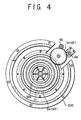
- FIG. 5 shows a second preferred form of three-part plate cylinder apparatus according to the invention.
- This second form is similar to its FIG. 1 counterpart in the construction of the three-part plate cylinder PC, of the circumferential and lateral adjustments R 21 and R 22 for the plate cylinder first or right-hand end part 2, and of the circumferential and lateral adjustments R 31 and R 32 for the plate cylinder second or left-hand end part 3.
- the difference resides in the fact that the circumferential adjustment R 11 and lateral adjustment R 12 for the plate cylinder center part 1 are both mounted outside the first or right-hand framing wall F 1 .
- the plate cylinder center part trunnion 1 d is coupled via the first driven helical gear 10 to both plate cylinder center part circumferential adjustment R 11 and plate cylinder center part lateral adjustment R 12 .
- the first driven helical gear 10 meshes with the first driving helical gear HG 1 and is further internally straight-splined at 10 a to mesh with the externally straight-splined member 10 b coaxially mounted fast to the projecting end of the plate cylinder center part first trunnion 1 d .
- the splined member 10 b is shown to be funnel-shaped in this alternate embodiment.
- the first driven helical gear 10 functions to transmit the rotation of the driving helical gear HG 1 to the plate cylinder center part first trunnion 1 d while being free to travel axially relative to the latter.
- the plate cylinder center part circumferential adjustment R 11 includes the bearing housing 11 coaxially affixed to the first driven helical gear 10 for carrying the bearing 11 a .
- the internally threaded ring 12 is coaxially mounted on, and threadedly engaged with, an externally screw-threaded rod 501 which forms a part of both plate cylinder center part circumferential adjustment R 11 and plate cylinder center part lateral adjustment R 12 .
- the threaded rod 501 is rotatably and coaxially coupled at its left-hand end to the plate cylinder center part trunnion 1 d via a bearing 502 a mounted to a bearing housing 502.
- the threaded rod 501 is therefore free to rotate relative to the plate cylinder center part trunnion 1 d but is constrained to joint axial travel therewith.
- the right-hand end of the threaded rod 501 extends through, and is threadedly engaged with, an internally screw-threaded sleeve 23 which is mounted to the end wall 101 of the enclosure 100 on the first framing wall F 1 and which forms a part of the plate cylinder center part lateral adjustment R 12 yet to be detailed.
- the driven gear 14 meshes with the drive pinion 16 on the output shaft of the plate cylinder center part circumferential adjustment motor 15 mounted to the enclosure end wall 101.
- the bidirectional rotation of the plate cylinder center part circumferential adjustment motor 15 will be imparted to the internally threaded ring 12 via the intermeshing gears 14 and 16.
- the internally threaded ring 12 will travel axially of the threaded rod 501 by virtue of its threaded engagement therewith.
- the first driven helical gear 10 will travel axially and, by reason of its sliding engagement with the helical gear HG 1 on one of the blanket cylinder trunnions, circumferentially as well.
- first driven helical gear 10 will travel both axially and circumferentially as above, this axial motion will not be imparted to the plate cylinder center part first trunnion 1 d because of the straight-spline engagement of the helical gear 10 with the member 10b on the trunnion 1 d . Only the rotation of the first driven helical gear 10 will be applied to the plate cylinder center part 1, causing the latter to be angularly displaced in either direction with its lateral position held unaltered.
- the driving torque of the first driving helical gear HG 1 will be transmitted to the plate cylinder center part 1 via the first driven helical gear 10 by virtue of the straight-spline engagement between these members 1 and 10, but not to the internally threaded ring 12 because of the interposition of the bearing 11 a therebetween.
- the plate cylinder center part first trunnion 1 d is also coupled to the lateral adjustment R 12 for causing lateral displacement of the plate cylinder center part 1 in this alternate embodiment.
- the plate cylinder center part lateral adjustment R 12 includes an internally screw-threaded sleeve 23 which is mounted fast to the enclosure end wall 101 and which fits over the externally screw-threaded rod 501.
- This rod forms as aforesaid a part of both plate cylinder center part circumferential adjustment R 11 and plate cylinder center part lateral adjustment R 12 .
- the threaded rod 22 has coaxially mounted on its end the driven gear 24 in mesh with the drive pinion 26 on the output shaft of the bidirectional plate cylinder center part lateral adjustment motor 25.
- the bidirectional rotation of the plate cylinder center part lateral adjustment motor 25 will be imparted to the threaded rod 501 via the intermeshing gears 24 and 26. Thereupon the threaded rod 501 will undergo both angular and axial motion by virtue of its sliding engagement with the internally threaded sleeve 23. Since the threaded rod 501 is coupled to the plate cylinder center part first trunnion 1 d via the bearing 502 a , only the axial travel of the threaded rod will'be transmitted to the trunnion. Thus the plate cylinder center part 1 will adjustably travel laterally in either of two opposite directions.
- the internally threaded ring 12 will remain stationary in the face of the above combined angular and axial motion of the threaded rod 501.
- the axial travel of the plate cylinder center part first trunnion 1 d will not be transmitted to the first driven helical gear 10, either, by virtue of the straight-spline engagement therebetween. Consequently, the plate cylinder center part 1 will undergo no angular displacement but only travel laterally.
- the plate cylinder center part 1 will rotate as the first driving helical gear HG 1 imparts its rotation to the first driven helical gear 10 in straight-spline engagement with the plate cylinder center part first trunnion 1 d . This rotation of the plate cylinder center part first trunnion 1 d will not be transmitted to the threaded rod 501 because of the presence of the bearing 502 a therebetween.
- FIG. 5 embodiment The operation of this FIG. 5 embodiment is considered self-evident from the foregoing operational description of the FIGS. 1-4 embodiment.
Landscapes
- Engineering & Computer Science (AREA)
- Mechanical Engineering (AREA)
- Rotary Presses (AREA)
Applications Claiming Priority (2)
| Application Number | Priority Date | Filing Date | Title |
|---|---|---|---|
| JP2001305394 | 2001-10-01 | ||
| JP2001305394A JP3692992B2 (ja) | 2001-10-01 | 2001-10-01 | 3分割版胴装置 |
Publications (3)
| Publication Number | Publication Date |
|---|---|
| EP1297951A2 true EP1297951A2 (fr) | 2003-04-02 |
| EP1297951A3 EP1297951A3 (fr) | 2004-03-24 |
| EP1297951B1 EP1297951B1 (fr) | 2008-02-27 |
Family
ID=19125195
Family Applications (1)
| Application Number | Title | Priority Date | Filing Date |
|---|---|---|---|
| EP02021095A Expired - Lifetime EP1297951B1 (fr) | 2001-10-01 | 2002-09-23 | Cylindre porte-plaque en trois parties avec des ajustements latéraux et circulaires pour l'enregistrement |
Country Status (4)
| Country | Link |
|---|---|
| US (1) | US6786147B2 (fr) |
| EP (1) | EP1297951B1 (fr) |
| JP (1) | JP3692992B2 (fr) |
| DE (1) | DE60225218T2 (fr) |
Cited By (4)
| Publication number | Priority date | Publication date | Assignee | Title |
|---|---|---|---|---|
| CN100564034C (zh) * | 2004-04-16 | 2009-12-02 | 曼罗兰公司 | 用于加工设备滚筒的直接传动装置 |
| CN108237774A (zh) * | 2016-12-27 | 2018-07-03 | 长胜纺织科技发展(上海)有限公司 | 横向对版系统 |
| CN108543676A (zh) * | 2018-06-27 | 2018-09-18 | 惠州市国鹏印刷股份有限公司 | 裱纸胶水厚度调节装置 |
| CN113118271A (zh) * | 2021-04-12 | 2021-07-16 | 江苏孜俊自动化科技有限公司 | 一种用于复合板加工的电控式无套封边装置 |
Families Citing this family (5)
| Publication number | Priority date | Publication date | Assignee | Title |
|---|---|---|---|---|
| US20050229800A1 (en) * | 2004-04-20 | 2005-10-20 | Heidelberger Druckmaschinen Ag | Plate cylinder with larger diameter central image area |
| DE102006008303B3 (de) * | 2006-02-23 | 2007-03-15 | Koenig & Bauer Ag | Rotationsdruckmaschine |
| US20100116159A1 (en) * | 2008-11-13 | 2010-05-13 | Larry Hines | Offset Printing Unit with Plate Cylinder Drive |
| EP2657021A1 (fr) * | 2012-04-24 | 2013-10-30 | KBA-NotaSys SA | Unité d'entraînement réglable d'une presse à imprimer et presse à imprimer, en particulier presse d'impression en creux la comprenant |
| CN103538357B (zh) * | 2013-10-17 | 2016-08-17 | 上海紫明印刷机械有限公司 | 印版滚筒位置校准装置 |
Citations (5)
| Publication number | Priority date | Publication date | Assignee | Title |
|---|---|---|---|---|
| JPS5931467A (ja) | 1982-08-16 | 1984-02-20 | Tech Res & Dev Inst Of Japan Def Agency | ドプラ追尾装置 |
| JPH0611769U (ja) | 1992-07-16 | 1994-02-15 | 憲 岡本 | ゴルフ用飛距離標示体 |
| JPH0638681U (ja) | 1992-10-30 | 1994-05-24 | 共栄工業株式会社 | 目隠し兼用の鏡付仕切板を備えた金属製家具 |
| JPH09141826A (ja) | 1995-11-27 | 1997-06-03 | Mitsubishi Heavy Ind Ltd | 印刷胴 |
| JP2726716B2 (ja) | 1989-10-26 | 1998-03-11 | 三菱重工業株式会社 | 輪転印刷機の分割版胴 |
Family Cites Families (9)
| Publication number | Priority date | Publication date | Assignee | Title |
|---|---|---|---|---|
| JPS5931467B2 (ja) * | 1977-04-27 | 1984-08-02 | 株式会社東京機械製作所 | 輪転印刷機における版胴装置 |
| JPS61125847A (ja) * | 1984-11-22 | 1986-06-13 | Hamada Insatsuki Seizosho:Kk | 印刷機における版のねじれ修正装置 |
| US4782752A (en) * | 1987-06-22 | 1988-11-08 | Pathfinder Graphic Associates Inc. | Control device for circumferential and lateral adjustment of printing cylinder |
| JPH05131608A (ja) * | 1991-11-14 | 1993-05-28 | Tokyo Kikai Seisakusho Ltd | 多色印刷機 |
| CA2090169A1 (fr) | 1992-03-12 | 1993-09-13 | Jerome F. Trumbetas | Cafe torrefie colloide comme aromatisant |
| JP3227807B2 (ja) | 1992-06-25 | 2001-11-12 | ソニー株式会社 | 透過型スクリーンの製造方法とスクリーン金型及び透過型マルチビジョンプロジェクタ |
| US6129015A (en) * | 1993-11-23 | 2000-10-10 | Quad/Tech, Inc. | Method and apparatus for registering color in a printing press |
| US5535675A (en) * | 1995-05-05 | 1996-07-16 | Heidelberger Druck Maschinen Ag | Apparatus for circumferential and lateral adjustment of plate cylinder |
| US6374731B1 (en) * | 1997-04-18 | 2002-04-23 | Heidelberger Druckmaschinen Ag | Lithographic newspaper printing press |
-
2001
- 2001-10-01 JP JP2001305394A patent/JP3692992B2/ja not_active Expired - Fee Related
-
2002
- 2002-09-23 EP EP02021095A patent/EP1297951B1/fr not_active Expired - Lifetime
- 2002-09-23 DE DE60225218T patent/DE60225218T2/de not_active Expired - Fee Related
- 2002-09-26 US US10/254,552 patent/US6786147B2/en not_active Expired - Fee Related
Patent Citations (5)
| Publication number | Priority date | Publication date | Assignee | Title |
|---|---|---|---|---|
| JPS5931467A (ja) | 1982-08-16 | 1984-02-20 | Tech Res & Dev Inst Of Japan Def Agency | ドプラ追尾装置 |
| JP2726716B2 (ja) | 1989-10-26 | 1998-03-11 | 三菱重工業株式会社 | 輪転印刷機の分割版胴 |
| JPH0611769U (ja) | 1992-07-16 | 1994-02-15 | 憲 岡本 | ゴルフ用飛距離標示体 |
| JPH0638681U (ja) | 1992-10-30 | 1994-05-24 | 共栄工業株式会社 | 目隠し兼用の鏡付仕切板を備えた金属製家具 |
| JPH09141826A (ja) | 1995-11-27 | 1997-06-03 | Mitsubishi Heavy Ind Ltd | 印刷胴 |
Cited By (6)
| Publication number | Priority date | Publication date | Assignee | Title |
|---|---|---|---|---|
| CN100564034C (zh) * | 2004-04-16 | 2009-12-02 | 曼罗兰公司 | 用于加工设备滚筒的直接传动装置 |
| CN108237774A (zh) * | 2016-12-27 | 2018-07-03 | 长胜纺织科技发展(上海)有限公司 | 横向对版系统 |
| CN108237774B (zh) * | 2016-12-27 | 2020-06-30 | 长胜纺织科技发展(上海)有限公司 | 横向对版系统 |
| CN108543676A (zh) * | 2018-06-27 | 2018-09-18 | 惠州市国鹏印刷股份有限公司 | 裱纸胶水厚度调节装置 |
| CN113118271A (zh) * | 2021-04-12 | 2021-07-16 | 江苏孜俊自动化科技有限公司 | 一种用于复合板加工的电控式无套封边装置 |
| CN113118271B (zh) * | 2021-04-12 | 2024-05-28 | 江苏孜俊自动化科技有限公司 | 一种用于复合板加工的电控式无套封边装置 |
Also Published As
| Publication number | Publication date |
|---|---|
| JP3692992B2 (ja) | 2005-09-07 |
| DE60225218D1 (de) | 2008-04-10 |
| EP1297951A3 (fr) | 2004-03-24 |
| US20030061955A1 (en) | 2003-04-03 |
| JP2003103749A (ja) | 2003-04-09 |
| US6786147B2 (en) | 2004-09-07 |
| DE60225218T2 (de) | 2009-03-05 |
| EP1297951B1 (fr) | 2008-02-27 |
Similar Documents
| Publication | Publication Date | Title |
|---|---|---|
| US7213513B2 (en) | Printing group pertaining to a printing machine having a linearly displaceable transfer cylinder | |
| US4606269A (en) | Register adjustment device for a rotary printing machine | |
| EP0400444B1 (fr) | Dispositif pour imprimer en couleur sur les deux faces du papier | |
| US6550383B2 (en) | Independent cylinder drive system for a multicolor offset lithographic press | |
| US7114439B2 (en) | Printing groups of a printing press | |
| US6786147B2 (en) | Three-part plate cylinder with lateral and circumferential adjustments for registration | |
| US4363270A (en) | Harmonic phasing device for printing press | |
| US4785734A (en) | Apparatus for controlling paper transfer speed of a printing section of a form printing machine | |
| JP2000094633A (ja) | ウェブ輪転印刷機のためのインプリント印刷ユニット | |
| US3724368A (en) | Harmonic drive register adjustment device for a printing press | |
| JP2541549B2 (ja) | オフセツト巻取り紙輪転印刷機用の印刷装置 | |
| JPH0286445A (ja) | フレキソ印刷機 | |
| US6901854B2 (en) | Drive mechanism of a printing unit | |
| JP2952440B2 (ja) | 多色印刷機 | |
| US7032510B2 (en) | Mounting for cylinders of a printing machines | |
| JP2779136B2 (ja) | 印刷機のための枚葉紙案内胴 | |
| JP3383947B2 (ja) | 多色刷用印刷ユニット | |
| ITVR20000013A1 (it) | Macchina da stampa rotativa flessografica a piu' colori | |
| JP3378230B2 (ja) | 印刷ユニット | |
| US5009157A (en) | Rotary press comprising an endless block belt | |
| US7293503B2 (en) | Slide-in print unit for a variable format in offset printing | |
| US20040231535A1 (en) | Printing groups of a printing press | |
| JPH05361Y2 (fr) | ||
| JP2000117949A (ja) | オフセット印刷機の駆動装置 | |
| JP2001038873A (ja) | 印刷装置およびその駆動方法 |
Legal Events
| Date | Code | Title | Description |
|---|---|---|---|
| PUAI | Public reference made under article 153(3) epc to a published international application that has entered the european phase |
Free format text: ORIGINAL CODE: 0009012 |
|
| 17P | Request for examination filed |
Effective date: 20020923 |
|
| AK | Designated contracting states |
Kind code of ref document: A2 Designated state(s): AT BE BG CH CY CZ DE DK EE ES FI FR GB GR IE IT LI LU MC NL PT SE SK TR Designated state(s): AT BE BG CH CY CZ DE DK EE ES FI FR GB GR IE IT LI LU MC NL PT SE SK TR |
|
| AX | Request for extension of the european patent |
Extension state: AL LT LV MK RO SI |
|
| PUAL | Search report despatched |
Free format text: ORIGINAL CODE: 0009013 |
|
| AK | Designated contracting states |
Kind code of ref document: A3 Designated state(s): AT BE BG CH CY CZ DE DK EE ES FI FR GB GR IE IT LI LU MC NL PT SE SK TR |
|
| AX | Request for extension of the european patent |
Extension state: AL LT LV MK RO SI |
|
| RIC1 | Information provided on ipc code assigned before grant |
Ipc: 7B 41F 13/16 B Ipc: 7B 41F 13/14 A |
|
| AKX | Designation fees paid |
Designated state(s): CH DE FR GB LI |
|
| 17Q | First examination report despatched |
Effective date: 20060922 |
|
| GRAP | Despatch of communication of intention to grant a patent |
Free format text: ORIGINAL CODE: EPIDOSNIGR1 |
|
| GRAS | Grant fee paid |
Free format text: ORIGINAL CODE: EPIDOSNIGR3 |
|
| GRAA | (expected) grant |
Free format text: ORIGINAL CODE: 0009210 |
|
| AK | Designated contracting states |
Kind code of ref document: B1 Designated state(s): CH DE FR GB LI |
|
| REG | Reference to a national code |
Ref country code: GB Ref legal event code: FG4D |
|
| REG | Reference to a national code |
Ref country code: CH Ref legal event code: EP |
|
| REF | Corresponds to: |
Ref document number: 60225218 Country of ref document: DE Date of ref document: 20080410 Kind code of ref document: P |
|
| ET | Fr: translation filed | ||
| PGFP | Annual fee paid to national office [announced via postgrant information from national office to epo] |
Ref country code: FR Payment date: 20080715 Year of fee payment: 7 |
|
| PLBE | No opposition filed within time limit |
Free format text: ORIGINAL CODE: 0009261 |
|
| STAA | Information on the status of an ep patent application or granted ep patent |
Free format text: STATUS: NO OPPOSITION FILED WITHIN TIME LIMIT |
|
| PGFP | Annual fee paid to national office [announced via postgrant information from national office to epo] |
Ref country code: DE Payment date: 20080715 Year of fee payment: 7 |
|
| 26N | No opposition filed |
Effective date: 20081128 |
|
| REG | Reference to a national code |
Ref country code: CH Ref legal event code: PL |
|
| GBPC | Gb: european patent ceased through non-payment of renewal fee |
Effective date: 20080923 |
|
| PG25 | Lapsed in a contracting state [announced via postgrant information from national office to epo] |
Ref country code: LI Free format text: LAPSE BECAUSE OF NON-PAYMENT OF DUE FEES Effective date: 20080930 Ref country code: CH Free format text: LAPSE BECAUSE OF NON-PAYMENT OF DUE FEES Effective date: 20080930 |
|
| PG25 | Lapsed in a contracting state [announced via postgrant information from national office to epo] |
Ref country code: GB Free format text: LAPSE BECAUSE OF NON-PAYMENT OF DUE FEES Effective date: 20080923 |
|
| REG | Reference to a national code |
Ref country code: FR Ref legal event code: ST Effective date: 20100531 |
|
| PG25 | Lapsed in a contracting state [announced via postgrant information from national office to epo] |
Ref country code: FR Free format text: LAPSE BECAUSE OF NON-PAYMENT OF DUE FEES Effective date: 20090930 Ref country code: DE Free format text: LAPSE BECAUSE OF NON-PAYMENT OF DUE FEES Effective date: 20100401 |