EP1298270A2 - Pivotable shutter panel assembly - Google Patents
Pivotable shutter panel assembly Download PDFInfo
- Publication number
- EP1298270A2 EP1298270A2 EP02386011A EP02386011A EP1298270A2 EP 1298270 A2 EP1298270 A2 EP 1298270A2 EP 02386011 A EP02386011 A EP 02386011A EP 02386011 A EP02386011 A EP 02386011A EP 1298270 A2 EP1298270 A2 EP 1298270A2
- Authority
- EP
- European Patent Office
- Prior art keywords
- profile portion
- pair
- panels
- panel assembly
- profile
- Prior art date
- Legal status (The legal status is an assumption and is not a legal conclusion. Google has not performed a legal analysis and makes no representation as to the accuracy of the status listed.)
- Granted
Links
Images






Classifications
-
- E—FIXED CONSTRUCTIONS
- E06—DOORS, WINDOWS, SHUTTERS, OR ROLLER BLINDS IN GENERAL; LADDERS
- E06B—FIXED OR MOVABLE CLOSURES FOR OPENINGS IN BUILDINGS, VEHICLES, FENCES OR LIKE ENCLOSURES IN GENERAL, e.g. DOORS, WINDOWS, BLINDS, GATES
- E06B3/00—Window sashes, door leaves, or like elements for closing wall or like openings; Layout of fixed or moving closures, e.g. windows in wall or like openings; Features of rigidly-mounted outer frames relating to the mounting of wing frames
- E06B3/68—Window bars
-
- E—FIXED CONSTRUCTIONS
- E05—LOCKS; KEYS; WINDOW OR DOOR FITTINGS; SAFES
- E05D—HINGES OR SUSPENSION DEVICES FOR DOORS, WINDOWS OR WINGS
- E05D1/00—Pinless hinges; Substitutes for hinges
- E05D1/04—Pinless hinges; Substitutes for hinges with guide members shaped as circular arcs
-
- E—FIXED CONSTRUCTIONS
- E05—LOCKS; KEYS; WINDOW OR DOOR FITTINGS; SAFES
- E05D—HINGES OR SUSPENSION DEVICES FOR DOORS, WINDOWS OR WINGS
- E05D15/00—Suspension arrangements for wings
- E05D15/26—Suspension arrangements for wings for folding wings
-
- E—FIXED CONSTRUCTIONS
- E05—LOCKS; KEYS; WINDOW OR DOOR FITTINGS; SAFES
- E05D—HINGES OR SUSPENSION DEVICES FOR DOORS, WINDOWS OR WINGS
- E05D3/00—Hinges with pins
- E05D3/06—Hinges with pins with two or more pins
- E05D3/12—Hinges with pins with two or more pins with two parallel pins and one arm
-
- E—FIXED CONSTRUCTIONS
- E05—LOCKS; KEYS; WINDOW OR DOOR FITTINGS; SAFES
- E05D—HINGES OR SUSPENSION DEVICES FOR DOORS, WINDOWS OR WINGS
- E05D7/00—Hinges or pivots of special construction
- E05D7/02—Hinges or pivots of special construction for use on the right-hand as well as the left-hand side; Convertible right-hand or left-hand hinges
-
- E—FIXED CONSTRUCTIONS
- E06—DOORS, WINDOWS, SHUTTERS, OR ROLLER BLINDS IN GENERAL; LADDERS
- E06B—FIXED OR MOVABLE CLOSURES FOR OPENINGS IN BUILDINGS, VEHICLES, FENCES OR LIKE ENCLOSURES IN GENERAL, e.g. DOORS, WINDOWS, BLINDS, GATES
- E06B3/00—Window sashes, door leaves, or like elements for closing wall or like openings; Layout of fixed or moving closures, e.g. windows in wall or like openings; Features of rigidly-mounted outer frames relating to the mounting of wing frames
- E06B3/32—Arrangements of wings characterised by the manner of movement; Arrangements of movable wings in openings; Features of wings or frames relating solely to the manner of movement of the wing
- E06B3/48—Wings connected at their edges, e.g. foldable wings
- E06B3/481—Wings foldable in a zig-zag manner or bi-fold wings
-
- E—FIXED CONSTRUCTIONS
- E06—DOORS, WINDOWS, SHUTTERS, OR ROLLER BLINDS IN GENERAL; LADDERS
- E06B—FIXED OR MOVABLE CLOSURES FOR OPENINGS IN BUILDINGS, VEHICLES, FENCES OR LIKE ENCLOSURES IN GENERAL, e.g. DOORS, WINDOWS, BLINDS, GATES
- E06B9/00—Screening or protective devices for wall or similar openings, with or without operating or securing mechanisms; Closures of similar construction
- E06B9/02—Shutters, movable grilles, or other safety closing devices, e.g. against burglary
- E06B9/04—Shutters, movable grilles, or other safety closing devices, e.g. against burglary of wing type, e.g. revolving or sliding
-
- E—FIXED CONSTRUCTIONS
- E05—LOCKS; KEYS; WINDOW OR DOOR FITTINGS; SAFES
- E05Y—INDEXING SCHEME ASSOCIATED WITH SUBCLASSES E05D AND E05F, RELATING TO CONSTRUCTION ELEMENTS, ELECTRIC CONTROL, POWER SUPPLY, POWER SIGNAL OR TRANSMISSION, USER INTERFACES, MOUNTING OR COUPLING, DETAILS, ACCESSORIES, AUXILIARY OPERATIONS NOT OTHERWISE PROVIDED FOR, APPLICATION THEREOF
- E05Y2900/00—Application of doors, windows, wings or fittings thereof
- E05Y2900/10—Application of doors, windows, wings or fittings thereof for buildings or parts thereof
- E05Y2900/13—Type of wing
- E05Y2900/132—Doors
-
- E—FIXED CONSTRUCTIONS
- E06—DOORS, WINDOWS, SHUTTERS, OR ROLLER BLINDS IN GENERAL; LADDERS
- E06B—FIXED OR MOVABLE CLOSURES FOR OPENINGS IN BUILDINGS, VEHICLES, FENCES OR LIKE ENCLOSURES IN GENERAL, e.g. DOORS, WINDOWS, BLINDS, GATES
- E06B9/00—Screening or protective devices for wall or similar openings, with or without operating or securing mechanisms; Closures of similar construction
- E06B9/02—Shutters, movable grilles, or other safety closing devices, e.g. against burglary
- E06B9/06—Shutters, movable grilles, or other safety closing devices, e.g. against burglary collapsible or foldable, e.g. of the bellows or lazy-tongs type
- E06B9/0607—Shutters, movable grilles, or other safety closing devices, e.g. against burglary collapsible or foldable, e.g. of the bellows or lazy-tongs type comprising a plurality of similar rigid closing elements movable to a storage position
- E06B9/0615—Shutters, movable grilles, or other safety closing devices, e.g. against burglary collapsible or foldable, e.g. of the bellows or lazy-tongs type comprising a plurality of similar rigid closing elements movable to a storage position characterised by the closing elements
- E06B9/0638—Slats or panels
-
- E—FIXED CONSTRUCTIONS
- E06—DOORS, WINDOWS, SHUTTERS, OR ROLLER BLINDS IN GENERAL; LADDERS
- E06B—FIXED OR MOVABLE CLOSURES FOR OPENINGS IN BUILDINGS, VEHICLES, FENCES OR LIKE ENCLOSURES IN GENERAL, e.g. DOORS, WINDOWS, BLINDS, GATES
- E06B9/00—Screening or protective devices for wall or similar openings, with or without operating or securing mechanisms; Closures of similar construction
- E06B9/02—Shutters, movable grilles, or other safety closing devices, e.g. against burglary
- E06B9/06—Shutters, movable grilles, or other safety closing devices, e.g. against burglary collapsible or foldable, e.g. of the bellows or lazy-tongs type
- E06B9/0607—Shutters, movable grilles, or other safety closing devices, e.g. against burglary collapsible or foldable, e.g. of the bellows or lazy-tongs type comprising a plurality of similar rigid closing elements movable to a storage position
- E06B9/0646—Shutters, movable grilles, or other safety closing devices, e.g. against burglary collapsible or foldable, e.g. of the bellows or lazy-tongs type comprising a plurality of similar rigid closing elements movable to a storage position characterised by the relative arrangement of the closing elements in the stored position
- E06B9/0669—Shutters, movable grilles, or other safety closing devices, e.g. against burglary collapsible or foldable, e.g. of the bellows or lazy-tongs type comprising a plurality of similar rigid closing elements movable to a storage position characterised by the relative arrangement of the closing elements in the stored position stored in a zig-zag arrangement
Definitions
- the present invention relates to the field of shutter panels and more particularly provides a functionally organized system of profiles for a reliable, low cost shutter panel assembly process.
- Pivotable panel assemblies known in the prior art comprise at least one or a plurality of mutually articulated shutter panels, connected to elongated vertical mounting members fixed to either one or either of the vertical walls on either side of the opening in which the shutter panel assembly is installed.
- each one of the shutter panels to either an adjacent panel or to the vertical mounting member fixed to the wall is made by means of a number of distinctly spaced conventionally known hinges.
- One upper, one bottom and one intermediate hinge are normally used in each said pivotable connection.
- This plurality of hinges necessitates skill and excessive time for installation of the shutter panel assembly, thereby leading to an increased cost thereof.
- this increased cost does not necessarily lead towards satisfactory safety and aesthetics, since the hinges are apparent from the outside and thereby provoke thieves violating the shutter panel therefrom, whilst they also contribute negatively towards the aesthetics of the structure.
- pivotable connection of the prior art enhances the passages via which air may enter into the building, thereby maximizing heating and/or air conditioning expenditure.
- the object of the invention is to efficiently overcome the above mentioned drawbacks of shutter panels of the prior art by providing in combination one single elongated hinge profile portion extending along the entire vertical length of each of the panels and of the mounting member, said elongated hinge profile portion being provided with at least one pair of adjacent uniformly oriented circular sectors, a frame profile portion surrounding and supporting the panel in a rectangular configuration and presenting a pair of annular recesses at the circumference thereof for receiving any of said pair of adjacent, uniformly oriented circular sectors of said elongated hinge profile portion and a mounting member profile portion for receiving any of said pair of adjacent, uniformly oriented circular sectors of said elongated hinge profile portion wherein the pivotable shutter panel assembly is made using one said elongated hinge profile portion for each pair of adjacent panels and engaging each one of said pair of adjacent, uniformly oriented circular sectors of the elongated hinge profile portion within each one of opposing annular recesses of the frame profile portion of said pair of adjacent panels and using one said elongated hinge profile portion to connect the frame profile portion
- An object of the present invention is therefore the employment of such elongated hinge profile portions in a pivotable shutter panel assembly in order to minimize labour and accessories cost associated with the panel assembling process and standardizing the process by minimizing skill dependent operations thereof and producing a panel assembly of improved safety and aesthetic standards with the hinge profile portions being entirely hidden within said annular recesses of adjacent panels or of the mounting member profile portion and not protruding therefrom.
- Still another object of the invention is to enhance safety against undesirable violation of the proposed pivotable shutter panel assembly by providing a further central tubular recess along said frame profile portion and using locking bolts reciprocatingly moving along said tubular recesses, thereby effecting locking of the panel assembly at a variety of points.
- the proposed mounting member profile portion is advantageously provided with a recess for receiving said reciprocatingly moving locking bolts.
- Still another object of the invention is to provide said elongated hinge profile portion with a third circular sector located at the other side of a planar surface from that including said pair of adjacent, uniformly oriented circular sectors and oriented in a diametrically opposite direction therefrom, said third circular sector being provided with a pin being introduced into a suitable recess of a frame mounting member profile portion mounted horizontally on the ceiling of the opening wherein said shutter panel assembly is installed, thereby providing a guided process of folding adjacent panels one against the other when the shutter panel assembly comprises a plurality of panels and it is moved in an opening or closing direction.
- An equivalent arrangement is equally useful in a sequential arrangement of foldable wall partition panels.
- a further object of the invention is to propose a variety of accessories, which are functionally related to said pivotable shutter panel assembly, such as the covering plate profile portions used in the central junction wherein two shutter panel surfaces cross each other when the shutter is brought at a closed position or elongated hinge extension profile portions being used at the side of the mounting member profile portion for overturning a folded shutter panel assembly from a direction parallel to the mounting member profile portion in contact with the side wall of the opening to a direction parallel to the frontal wall surface of the building.
- accessories which are functionally related to said pivotable shutter panel assembly, such as the covering plate profile portions used in the central junction wherein two shutter panel surfaces cross each other when the shutter is brought at a closed position or elongated hinge extension profile portions being used at the side of the mounting member profile portion for overturning a folded shutter panel assembly from a direction parallel to the mounting member profile portion in contact with the side wall of the opening to a direction parallel to the frontal wall surface of the building.
- Another object of the invention is to propose alternative means of filling materials for the shutter panels, including profile systems for dividing the panel into a plurality of rectangular frames and alternative types of grilles including possibility of openings therein between for the entrance of light and/or air.
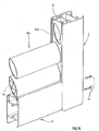
- the key element of the present invention is the elongated hinge profile portion 1.
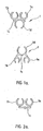
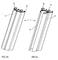
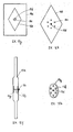
- the hinge profile portion 1 comprises at least one pair of adjacent uniformly oriented circular sectors 1a and 1b extending on the same side of a planar surface 1c (Fig. 2a, 2b) and preferably including a third circular sector 1d located at the other side of the planar surface 1c from that on which are located the circular sectors 1a and 1b (Fig. 1a, 1b).
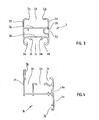
- Fig. 3 shows a typical embodiment of the frame profile portion 2, that is employed in combination with the hinge profile portion 1 and is used in the manufacturing process of the panels for the proposed shutter panel assembly, wherein it surrounds and supports the selected panels in rectangular configuration.
- the frame profile portion 2 includes a pair of parallel planar surfaces 2e and 2f joined by internal parallel members 2g and 2h.
- a safety enhancing feature of the invention is the inclusion of a suitably formed steel member 5 within the gap in between internal parallel members 2g and 2h, as illustratively shown in Fig. 6b.
- Parallel planar surfaces 2e, 2h of the frame profile portion 2 are spaced at such as distance as to form opposing openings 2c and 2d at the two ends thereof, wherein on either side of opening 2c the parallel planar surfaces are curved and a pair of annular recesses 2a and 2b are formed, whilst on either side of opening 2d the parallel planar surfaces 2a,2b turn at right angles projections 2p, 2q forming the basement for receiving a panel filling material 10.
- a mounting member profile portion is necessarily used on the vertical sides of the wall so as to be connected with a shutter panel assembly openable on either side, but preferably it is also lined horizontally, both on the ceiling wall and/or the ground surface of the opening, thereby offering the recess means 3k capable of receiving locking bolt means installed within central tubular recesses 2j of frame profile portions 2 and moving reciprocatingly in the vertical direction, thereby offering the possibility of locking the shutter panel assembly at a variety of points. As shown in Fig.
- the mounting member profile portion comprises a pair of parallel planar surfaces 3e and 3f, wherein the planar surface 3f covers the wall 34 at the interior of the building, whilst planar surface 3e extends into an annular recess formation 31, similar to the annular recesses 2a,2b of the frame profile portion 2.
- the mounting member profile portion might be made in two cooperating pieces 3a and 3b, wherein profile piece 3a is similar to the singular profile piece 3c of Fig. 4 and receives an additional profile piece 3b which is provided with a pair of annular recesses 31 on either side thereof.
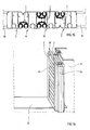
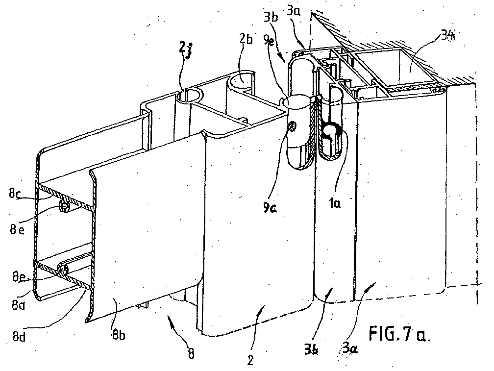
- the pivotable connection of adjacent panels of the shutter panel assembly or of the first panel thereof to the mounting member profile 3 fixedly mounted onto the side wall is implemented with the single elongated hinge profile portion 1, that extends along the vertical length of frame profile portion 2 and mounting member profile portion 3 when one of the pair of circular sectors 1a,1b of the hinge profile portion 1 is introduced into one of the pair of annular recesses 2a,2b of the frame profile portion 2 of one panel of the shutter panel assembly and the other one of the pair of circular sectors 1a,1b of the hinge profile portion 1 is introduced into one of the pair of annular recesses 2a,2b of the frame profile portion 2 of an adjacent panel of the shutter panel assembly or eventually into an annular recess 31 of the vertically extending mounting member profile portion 3.
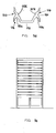
- Such pivotable connection of the profiles of the invention is illustratively shown in either one of the Figures 4a,4b,5a,5b,7a,7b.
- the hinge profile portion 1 is cut at a length somewhat shorter than the vertical length of either frame profiles 2 surrounding and supporting the panels of the pivotable shutter panel assembly or of the mounting member profile 3 fixedly mounted at the side walls, so that it may be plugged at the top and bottom thereof as shown in Fig. 7a and fig. 7b respectively with plug means 9, which has a tubular form with dimensions such as to fit within one of the annular recesses 2a,2b or 31 and may alternatively take the following forms:
- Figs. 7a and 7b also illustrate the employment of planar profile portion 8 which might be used as an alternative horizontally extending profile in each one of the rectangularly formed panels.
- Planar profile portion 8 comprises a pair of exterior parallel planar surfaces 8a,8b and a pair of internal parallel surfaces 8c, 8d perpendicularly disposed on the above exterior planar surfaces to connect them.
- Each one of the internal parallel surfaces 8c,8d is provided with a longitudinally extending nerve forming an opening 8e.
- the rectangular frame surrounding and supporting each one of the panels of the shutter panel assembly of the invention is normally constructed as shown in Fig. 11 or 12, wherein pieces of the same frame profile portion 2 extend both vertically and horizontally and are cut at an angle of 45° at the junction corners thereof thereby being screwed therein by means of screws 13 after a preferential metallic angular fixture 15 is introduced at such corner being fixedly inserted within the gaps in between internal parallel surfaces 2g, 2h of frame profile portions 2.
- the rectangular frame surrounding and supporting each one of the panels of the shutter panel assembly of the invention may alternatively be constructed as shown in Fig. 9 or 10, wherein pieces of the same frame profile portion 2 extend vertically, but the horizontally extending pieces are chosen to be of the aforementioned planar profile portion 8. In this case an angular cut at the junction corner of the profiles is not necessary and screws 13 are used that pass through the vertically extending frame profile portion 2 to fixedly enter into the longitudinally extending nerves with openings 8e of the planar profile portion 8.
- the filling material for the panels themselves may alternatively be either one of the following:
- a means to do that is a profile portion 30 depicted in Figs. 15 and 16, which is identical with the frame profile portion 2, but further including a pair of annular recesses at both ends thereof. If two or more profile portions 30 are connected together by means of hinge profile portions 1, one hinge profile portion for each pair of annular recesses thereof, there is formed a desirably long rigid interface in between two pivotally foldable panels.
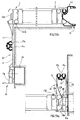
- Profile 30 is useful in wall partition structures, such as those depicted in Fig. 18, wherein a mounting member profile portion 3 is lined both on the upper and bottom surface of the opening wherein the partition is installed and wherein as shown in Figs. 17a,17b, the profile 30 provides for a necessary rigid interface, whilst in the same figures will be noticed the employment of the third circular sector 1d of the hinge profile portion 1 in the role of receiving a suitable shaft (not shown) which is engaged within the longitudinally extending opening 3m of the mounting member profile portion 3 so as to provide guided development of the pivotable panel assembly along the predetermined, by the horizontally lined mounting member profile portion 3, direction, as well as the use of reciprocatingly movable bolts 30, passing through the tubular recesses 2j of frame profile portions 2, so as to lock, both on the top and the bottom, the panel assembly at desired variety of locations.
Landscapes
- Engineering & Computer Science (AREA)
- Structural Engineering (AREA)
- Mechanical Engineering (AREA)
- Civil Engineering (AREA)
- Architecture (AREA)
- Operating, Guiding And Securing Of Roll- Type Closing Members (AREA)
- Extensible Doors And Revolving Doors (AREA)
- Load-Bearing And Curtain Walls (AREA)
- Seal Device For Vehicle (AREA)
- Wing Frames And Configurations (AREA)
Abstract
Description
- a single or
double glass panel 11, as illustratively shown in Fig. 11. - a single or
double glass panel 11, divided into a plurality of rectangular frames, as illustratively shown in Fig. 12. In this embodiment a pair of divider profiles 16a and 16b are used, which present an external trapezoidal section (another form might also be chosen) and wherein either side of the basement of divider profiles 16a, 16b includes recesses 17a and 17b respectively for insertion of a rubber pad offering a safe contact with the glass panel surfaces. Divider profile 16a extends into a pair oflegs 19a which are provided with opposing protrusions 18a that cooperate withprotrusions 18b of divider profile 16b in the assembly process of these divider profiles with a single or double glass panel therein between, as illustrated in Fig. 12e and Fig. 12f respectively. - a non transparent panel surface 11a employed throughout the panel
or at selected portions of the rectangular frames being built with the above
mentioned divider profiles, wherein at certain selected locations of such non
transparent panel surfaces 11a a mechanism of desirably controlling light
passage is installed, which as illustratively shown in Figs. 12g-12k
comprises a first circular arrangement of
holes 11c opened at a rhomboid surface included within said non transparent panel surface 11a and a second homologous circular arrangement of holes 11h opened at the circumference of acircular plate 11g (Fig. 12k) that is rotatable by means of alever 11e (Fig. 12j) passing through the center of thecircular plate 11g, so as to either bring the abovementioned first and second arrangement ofholes 11c, 11h in alignment thereby allowing light to pass therefrom or block passage of light if these holes are not aligned. - an arrangement of parallel grilles, two alternative grilles being illustrated:
-
grilles 10a of generally rectangular cross section shown in Fig. 9, 9a, each one with a trapezoidal form at the top thereof and each comprising a pair of parallel planar surfaces 103,104 (Fig. 9b) interconnected by means ofinternal nerves 105. Planar surfaces 103, 104 converge into inwards inclined ends 103a, 104a at the bottom thereof and into inwards inclined ends 103b, 104b at the top thereof, whereinadjacent grilles 10a are engaged withprotrusions
In accordance with a preferred embodiment of the invention, a special air/light allowing profile 10b might be interposed betweenadjacent grilles 10a (Fig. 9c). As shown in Fig. 9d, the special air/light allowing profile 10b includes aplanar surface 108 with extension members 109,110 at the ends thereof, with corresponding recesses 109a,109b on theextension member 109 and corresponding recesses 110a, 110b on theextension member 110 which fit into corresponding end formations ofgrilles 10a. Insertion of such special air/light allowing profiles 10b in between selected regions ofadjacent grilles 10a provides as shown in Fig. 9e desirable passages of air and light. Two or more short lengths ofprofile 10b are sufficient to form the desired spacing between adjacent grilles. - grilles 10c of generally elliptical cross section shown in Fig. 10. In
this embodiment a
rectangular bar 12 is introduced within theopening 2d of theframe profile portion 2 andelliptical openings 12a are made therein for receiving the elliptical grilles 10c. In accordance with a preferred embodiment of the invention ametal sheet 5a is internally incorporated in grilles 10c, thereby providing enhanced safety against grille violation.
- A covering plate profile portion 4 being used in the central junction
wherein two cooperating shutter panel assemblies cross each other, wherein
this covering plate profile portion 4a is connected to the end frame profile
portions of the two cooperating shutter panel assemblies and in a first
preferred embodiment of the invention (Fig. 6) comprises a generally planar
frontal covering surface 4d which aesthetically covers the junction and includes an endinternal recess 4e wherein a rubber pad is introduced to effect noiseless operation and insulation properties. In a second preferred embodiment of the invention depicted in Fig. 6a, the coveringplate profile portion 4b is again provided with thefrontal covering surface 4d andend recess 4e for inclusion of the rubber pad, but its mounting surface onto the vertically extendingframe profiles 2 is implemented with a mountingsurface 4f which locks within the planar recess withend projections frame profile 2. In a third preferred embodiment of the invention depicted in Fig. 6b, the covering plate profile portion 4c is again provided with thefrontal covering surface 4d andend recess 4e for inclusion of the rubber pad, but its mounting surface onto the vertically extendingframe profiles 2 is implemented with anend circular sector 41 thereof, which rotatably fits within one of the pair ofannular recesses frame profile portion 2. In Fig. 13b the same endframe profile portion 2 of the shutter panel assembly is shown alternatively comprising a covering plateprofile portion type 4b on one side and a covering plate profile portion type 4c on the other side thereof. - In the above mentioned
tubular recess 2j of theframe profile portion 2, further safety enhancing features might be employed as by way of example the latch element 6 used to keep close together two cooperating shutter panel arrangements at the junction thereof, the latch element being depicted in Fig. 6a, and comprising an angular piece of twolinear elements angle region 6c in between them and with a pair ofgrooves linear elements tubular recess 2j of the end frame profile portion of one of the shutter panel arrangements and may be latched at 7b with a button means 7b passing through thetubular recess 2j of the end frame profile portion of the other one of the shutter panel arrangements.
The abovetubular recess 2j offrame profile portions 2 might also receive the above mentioned reciprocatingly movable locking bolts or other locking means, such as a rotatable lever lock, etc, such locking elements working withinrecesses 3k of the mounting member profile portion 3. - An elongated hinge
extension profile portion 20, which is illustratively shown in Figs. 13a-13b in a closed and opened position respectively of the proposed shutter panel assembly. This hingeextension profile portion 20 comprises twosimilar member portions recesses 21c, 22c for the reception of any of the circular sectors of thehinge profile portion 1. Thus ahinge profile portion 1 is used for rotatably connecting the twomembers extension profile portion 20, thereby offering movement of the same in the two abovementioned positions. Another illustrative embodiment of the hingeextension profile portion 20 is also depicted in Fig. 14.
Claims (9)
- Pivotable shutter panel assembly characterized in that it comprises in combination
a single elongated hinge profile portion (1) extending along the vertical length of each one of the panels and of the mounting member (3), said elongated hinge profile portion (1) being provided with at least one pair of adjacent uniformly oriented circular sectors (1a,1b),
a frame profile portion (2) for surrounding and supporting each one of the panels in a rectangular configuration and presenting a pair of annular recesses (2a,2b) at one side thereof for receiving any of said pair of adjacent, uniformly oriented circular sectors (1a,1b) of said elongated hinge profile portion(1), and
a mounting member profile portion (3) presenting at least one annular recess (31) for receiving any of said pair of adjacent, uniformly oriented circular sectors (1a,1b) of said elongated hinge profile portion (1), wherein the pivotable shutter panel assembly is constructed using one said elongated hinge profile portion (1) for each pair of adjacent panels and engaging each one of said pair of adjacent, uniformly oriented circular sectors (1a,1b) of the elongated hinge profile portion (1) within each one of opposing annular recesses (2a,2b) of the frame profile portion (2) of said pair of adjacent panels and using one said elongated hinge profile portion (1) to connect one of said pair of annular recesses (2a,2b) of the frame profile portion (2) of the first one of said panels to said annular recess (31) of the mounting member profile portion (3). - Pivotable shutter panel assembly as claimed in the above claim 1, characterized in that said hinge profile portion (1) is cut at a length somewhat shorter than the vertical length of either said frame profiles (2) surrounding and supporting the panels of the pivotable shutter panel assembly or of said mounting member profile (3) fixedly mounted at the side walls, so that it may be plugged at the top and bottom thereof respectively with plug means (9), said plug means (9) having a tubular form with dimensions such as to fit within one of the annular recesses (2a,2b) of said frame profile portions (2) or the annular recess (31) of the mounting member profile (3) and may alternatively take the form of a plug means (9a), comprising a cylindrical body (9e) with a transverse opening (9c), a bolt (9d) being screwed within opening (9c) so as to touch upon the surface of the annular recess (2a,2b) or (31), thereby fixedly mounting the plug means (9a) therein or a plug means (9b), comprising a cylindrical body (9g) with an acute threading at the circumference thereof and a head (9f) which is used to drive the cylindrical body (9g) within the annular recess (2a,2b) or (31), thereby opening a grooved receiving and stabilizing threading therein.
- Pivotable shutter panel assembly as claimed in the above claim 1, characterized in that a planar profile portion (8) might be used as an alternative horizontally extending profile in each one of the rectangularly formed panels, wherein said planar profile portion (8) comprises a pair of exterior parallel planar surfaces (8a,8b) and a pair of internal parallel surfaces (8c,8d) perpendicularly disposed on the above exterior planar surfaces to connect them and each one of said internal parallel surfaces (8c,8d) is provided with a longitudinally extending nerve forming an opening (8e) and wherein the rectangular frame surrounding and supporting each one of the panels of the shutter panel assembly is alternatively constructed either
by using pieces of the same frame profile portion (2) extending both vertically and horizontally, said pieces being cut at an angle of 45° at the junction corners thereof, subsequently being screwed therein by means of screws (13) after a preferential metallic angular fixture (15) is introduced at such corner being fixedly inserted within the gaps in between internal parallel surfaces (2g, 2h) of said frame profile portions (2), or
or by using pieces of the same frame profile portion (2) extending vertically, in combination with horizontally extending pieces of said planar profile portion (8), and using screws (13) that pass through the vertically extending frame profile portion (2) to fixedly enter into the longitudinally extending nerves with openings (8e) of the planar profile portion (8). - Pivotable shutter panel assembly as claimed in the above claim 1, characterized in that the filling material for the panels may alternatively be either one of the following:a single or double glass panel (11),a single or double glass panel (11), divided into a plurality of rectangular frames, wherein a pair of divider profiles (16a,16b) are used, which present an external trapezoidal section and wherein either side of the basement of said divider profiles (16a,16b) includes recesses (17a,17b) respectively for insertion of a rubber pad offering a safe contact with the glass panel surfaces and wherein said divider profile (16a) extends into a pair of legs (19a) being provided with opposing protrusions (18a) that cooperate with protrusions (18b) of said divider profile (16b) in the assembly process of these divider profiles with a single or double glass panel therein between,a non transparent panel surface (11a) employed throughout the panel or at selected portions of the rectangular frames being built with said divider profiles (16a,16b), wherein at certain selected locations of said non transparent panel surfaces (11a) a mechanism of desirably controlling light passage is installed, said mechanism comprising a first circular arrangement of holes (11c) opened at a rhomboid surface included within said non transparent panel surface (11a) and a second homologous circular arrangement of holes (11h) opened at the circumference of a circular plate (11g) that is rotatable by means of a lever (11e) passing through the center of the circular plate (11g) so as to either bring the first and second arrangement of holes (11c, 11h) in alignment thereby allowing light to pass therefrom or block passage of light if these holes are not aligned.
- Pivotable shutter panel assembly as claimed in the above claim 1, characterized in that the filling material for the panels may alternatively be either one of the following:an arrangement of parallel grilles (10a) of generally rectangular cross section, each one of said grilles with a trapezoidal form at the top thereof and each comprising a pair of parallel planar surfaces (103,104) interconnected by means of internal nerves (105), said planar surfaces (103, 104) converging into inwards inclined ends (103a,104a) at the bottom thereof and into inwards inclined ends (103b,104b) at the top thereof, wherein adjacent grilles (10a) are engaged with protrusions (111,112) to form a continuous panel surface and a special air/light allowing profile (10b) is selectively interposed between adjacent grilles (10a), said special air/light allowing profile (10b) including a planar surface (108) with extension members (109,110) at the ends thereof, with corresponding recesses (109a,109b) on the extension member (109) and corresponding recesses (110a, 110b) on the extension member (110) which fit into corresponding end formations of grilles (10a), wherein insertion of said special air/light allowing profiles (10b) in between selected regions of adjacent grilles (10a) provides desirable passages of air and light, oran arrangement of parallel grilles (10c) of generally elliptical cross section, wherein a rectangular bar (12) is introduced within side opening (2d) of said frame profile portion (2) and elliptical openings (12a) are made therein for receiving the elliptical grilles (10c).
- Pivotable shutter panel assembly as claimed in the above claim 1, characterized in that said mounting member profile portion (3) is lined both on the upper and bottom surface of the opening wherein said pivotable shutter panel assembly is installed and in that said elongated hinge profile portion (1) includes a third circular sector (1d) located on the other side of a planar surface (1c) thereof from that in which are located said pair of uniformly oriented circular sectors (1a,1b), said third circular sector receiving a pin, said pin being engaged within a longitudinally extending opening (3m) of said horizontally lined mounting member profile portion (3) so as to provide guided development of the pivotable shutter panel assembly along the predetermined, by the horizontally lined mounting member profile portion (3), direction, and in that reciprocatingly movable bolts (30) or other locking means, passing through a tubular recesses (2j) of said frame profile portions (2) effect locking, when being inserted within correspondingly shaped and aligned recesses (3k) of said horizontally lined mounting member profile portion (3), both on the top and the bottom, of the pivotable shutter panel assembly at desired variety of locations.
- Pivotable shutter panel assembly as claimed in the above claim 1, characterized in that it further includes means for the creation of a rigid interface in between pivotally foldable panels, said means being a profile portion (30), which is identical with said frame profile portion (2), but further including a pair of annular recesses at both ends thereof, wherein if two or more profile portions (30) are connected together by means of hinge profile portions (1), one hinge profile portion (1) for each pair of annular recesses thereof, there is formed a desirably long rigid interface in between two pivotally foldable panels.
- Pivotable shutter panel assembly as claimed in the above claim 1, characterized in that it further includes a covering plate profile portion (4) being used in the central junction wherein two cooperating shutter panel assemblies cross each other, wherein said covering plate profile portion (4) is connected to the end frame profile portions (2) of the two cooperating shutter panel assemblies and comprises a generally planar frontal covering surface (4d) which aesthetically covers the junction and includes an end internal recess (4e) wherein a rubber pad is introduced to effect noiseless operation and insulation properties, wherein said covering plate profile portion (4) is either fixedly mounted into said vertically extending end frame profile portion (2) by means of a fixed mounting surface (4f) which locks within a planar recess with end projections (21) and (2m) of said frame profile (2) or said covering plate profile portion (4) includes an end circular sector (41), which rotatably fits within one of the pair of said annular recesses (2a,2b) of the frame profile portion (2).
- Pivotable shutter panel assembly as claimed in the above claim 1, characterized in that it further includes an elongated hinge extension profile portion (20), said elongated hinge extension profile portion (20) being used at the side of the mounting member profile portion (3) for overturning a folded shutter panel assembly from a direction parallel to the mounting member profile portion (3) in contact with the side wall of the opening to a direction parallel to the frontal wall surface of the building, said elongated hinge extension profile portion (20) comprising two similar rotatably connected member portions (21,22) which extend into corresponding recesses (21c,22c) for the reception of any of the circular sectors of a hinge profile portion (1) by means of which said rotatable movement is effected, whilst the free ends of said member portions (21,22) are connected to the mounting member profile portion (3) and the end frame profile portion (2) respectively.
Applications Claiming Priority (2)
| Application Number | Priority Date | Filing Date | Title |
|---|---|---|---|
| GR20010100400A GR1004013B (en) | 2001-08-16 | 2001-08-16 | Pivotable shutter panel assembly |
| GR2001100400 | 2001-08-16 |
Publications (4)
| Publication Number | Publication Date |
|---|---|
| EP1298270A2 true EP1298270A2 (en) | 2003-04-02 |
| EP1298270A3 EP1298270A3 (en) | 2003-07-02 |
| EP1298270A9 EP1298270A9 (en) | 2004-04-14 |
| EP1298270B1 EP1298270B1 (en) | 2008-07-02 |
Family
ID=10944804
Family Applications (1)
| Application Number | Title | Priority Date | Filing Date |
|---|---|---|---|
| EP02386011A Expired - Lifetime EP1298270B1 (en) | 2001-08-16 | 2002-08-13 | Pivotable shutter panel assembly |
Country Status (4)
| Country | Link |
|---|---|
| EP (1) | EP1298270B1 (en) |
| AT (1) | ATE399921T1 (en) |
| DE (1) | DE60227327D1 (en) |
| GR (1) | GR1004013B (en) |
Cited By (4)
| Publication number | Priority date | Publication date | Assignee | Title |
|---|---|---|---|---|
| EP1635009A3 (en) * | 2004-09-11 | 2007-05-16 | Howe Green Limited | Hinged wall access panel |
| WO2009012797A1 (en) | 2007-07-25 | 2009-01-29 | Mero-Tsk International Gmbh & Co. Kg | Device for connecting at least one planar element to a supporting structure and/or at least two planar elements to each other and planar cover |
| GB2506968A (en) * | 2012-08-07 | 2014-04-16 | Smart Systems Ltd | Bi-folding door with internal hinges |
| RU181183U1 (en) * | 2018-02-26 | 2018-07-05 | Общество с ограниченной ответственностью "Роникон" | SEPARATION PROFILE |
Families Citing this family (1)
| Publication number | Priority date | Publication date | Assignee | Title |
|---|---|---|---|---|
| US9062484B2 (en) | 2013-06-14 | 2015-06-23 | Qualitas Manufacturing, Inc. | Accordion shutter hinge assembly |
Family Cites Families (5)
| Publication number | Priority date | Publication date | Assignee | Title |
|---|---|---|---|---|
| DE8633829U1 (en) * | 1986-12-18 | 1987-03-19 | Dieter Klaiber, Markisen-Klaiber, 76189 Karlsruhe | Folding wall |
| US4878530A (en) * | 1987-04-03 | 1989-11-07 | Marielle Jean | Bathroom panel |
| DE9304204U1 (en) * | 1993-03-20 | 1993-05-13 | Rau, Dieter, 7340 Geislingen | Frame profile for sun, light, wind and weather protection devices or similar. |
| FR2736379B1 (en) * | 1995-07-07 | 1998-01-23 | Alugrip | ARTICULATION DEVICE |
| FR2769040B1 (en) * | 1997-09-26 | 2000-03-17 | Fermetures Pallaud | SLIDING DOORS FOR CLOSING WINDOWS DOORS-WINDOWS OR DOORS |
-
2001
- 2001-08-16 GR GR20010100400A patent/GR1004013B/en unknown
-
2002
- 2002-08-13 DE DE60227327T patent/DE60227327D1/en not_active Expired - Fee Related
- 2002-08-13 EP EP02386011A patent/EP1298270B1/en not_active Expired - Lifetime
- 2002-08-13 AT AT02386011T patent/ATE399921T1/en not_active IP Right Cessation
Cited By (4)
| Publication number | Priority date | Publication date | Assignee | Title |
|---|---|---|---|---|
| EP1635009A3 (en) * | 2004-09-11 | 2007-05-16 | Howe Green Limited | Hinged wall access panel |
| WO2009012797A1 (en) | 2007-07-25 | 2009-01-29 | Mero-Tsk International Gmbh & Co. Kg | Device for connecting at least one planar element to a supporting structure and/or at least two planar elements to each other and planar cover |
| GB2506968A (en) * | 2012-08-07 | 2014-04-16 | Smart Systems Ltd | Bi-folding door with internal hinges |
| RU181183U1 (en) * | 2018-02-26 | 2018-07-05 | Общество с ограниченной ответственностью "Роникон" | SEPARATION PROFILE |
Also Published As
| Publication number | Publication date |
|---|---|
| EP1298270A3 (en) | 2003-07-02 |
| EP1298270B1 (en) | 2008-07-02 |
| DE60227327D1 (en) | 2008-08-14 |
| GR1004013B (en) | 2002-10-10 |
| EP1298270A9 (en) | 2004-04-14 |
| ATE399921T1 (en) | 2008-07-15 |
Similar Documents
| Publication | Publication Date | Title |
|---|---|---|
| EP0428589B1 (en) | Connection system | |
| US4615142A (en) | Burglar bars | |
| US4000590A (en) | Security grille | |
| US7793463B1 (en) | Plantation style security shutters | |
| US20240200391A1 (en) | Door-ready molding | |
| EP1298270A2 (en) | Pivotable shutter panel assembly | |
| KR100994430B1 (en) | Insulation and security window frame for building and installation method thereof | |
| GB2457994A (en) | Security device for sliding door | |
| WO2002053863A1 (en) | Control system for windows, doors, or the like, and window, door, or the like with such a control system | |
| KR102506892B1 (en) | Thermal Bridge Reduced Window Frame for Folding door | |
| US20250172031A1 (en) | Door-ready molding | |
| EP1635009A2 (en) | Hinged wall access panel | |
| KR20180109830A (en) | Folding door construction method | |
| JP4322218B2 (en) | Complete retrofitting method for joinery frames | |
| US20080163549A1 (en) | Sliding Window Assebly Having Security Pane Unit | |
| EP0111126A1 (en) | Locking devices and assemblies incorporating such devices | |
| JP7019384B2 (en) | Composite sash structure | |
| CN222716802U (en) | Openable aluminum alloy grille | |
| KR102874494B1 (en) | The rotational structure of the gansal installed in the middle gate | |
| JP3332153B2 (en) | Construction method of outdoor structure | |
| JP2005201036A (en) | Peripheral frame mounting structure and mounting method | |
| JP3137602B2 (en) | Window sash | |
| KR102831951B1 (en) | Door security device | |
| KR200339803Y1 (en) | Prominenceless hinge for fire door having eccentric hinge axis | |
| JP3222401B2 (en) | window |
Legal Events
| Date | Code | Title | Description |
|---|---|---|---|
| PUAI | Public reference made under article 153(3) epc to a published international application that has entered the european phase |
Free format text: ORIGINAL CODE: 0009012 |
|
| AK | Designated contracting states |
Kind code of ref document: A2 Designated state(s): AT BE BG CH CY CZ DE DK EE ES FI FR GB GR IE IT LI LU MC NL PT SE SK TR |
|
| AX | Request for extension of the european patent |
Extension state: AL LT LV MK RO SI |
|
| PUAL | Search report despatched |
Free format text: ORIGINAL CODE: 0009013 |
|
| RIC1 | Information provided on ipc code assigned before grant |
Ipc: 7E 05D 3/06 B Ipc: 7E 05D 5/06 B Ipc: 7E 05D 7/02 B Ipc: 7E 05D 15/26 B Ipc: 7E 06B 3/48 B Ipc: 7E 05D 1/04 A |
|
| AK | Designated contracting states |
Designated state(s): AT BE BG CH CY CZ DE DK EE ES FI FR GB GR IE IT LI LU MC NL PT SE SK TR |
|
| AX | Request for extension of the european patent |
Extension state: AL LT LV MK RO SI |
|
| 17P | Request for examination filed |
Effective date: 20031231 |
|
| AKX | Designation fees paid |
Designated state(s): AT BE BG CH CY CZ DE DK EE ES FI FR GB GR IE IT LI LU MC NL PT SE SK TR |
|
| RAP1 | Party data changed (applicant data changed or rights of an application transferred) |
Owner name: MANTZIKAS, V., DIPL.-ING. Owner name: VALVIS, MICHAIL |
|
| RIN1 | Information on inventor provided before grant (corrected) |
Inventor name: VALVIS, MICHAIL Inventor name: MANTZIKAS, V., DIPL.-ING. |
|
| RAP1 | Party data changed (applicant data changed or rights of an application transferred) |
Owner name: VALVIS, KONSTANTINOS Owner name: VALVIS, MICHAIL |
|
| RIN1 | Information on inventor provided before grant (corrected) |
Inventor name: VALVIS, KONSTANTINOS Inventor name: VALVIS, MICHAIL |
|
| PUAJ | Public notification under rule 129 epc |
Free format text: ORIGINAL CODE: 0009425 |
|
| 32PN | Public notification |
Free format text: COMMUNICATION PURSUANT TO ART 96(2)EPC DATED 09.01.2006. ADDRESS OF SOLOMOU 8, PALEO FALIRO, ATTIKI, GREECE |
|
| RAP1 | Party data changed (applicant data changed or rights of an application transferred) |
Owner name: VALVIS, KONSTANTINOS Owner name: VALVIS, MICHAIL |
|
| RIN1 | Information on inventor provided before grant (corrected) |
Inventor name: VALVIS, KONSTANTINOS Inventor name: VALVIS, MICHAIL |
|
| 17Q | First examination report despatched |
Effective date: 20050929 |
|
| GRAP | Despatch of communication of intention to grant a patent |
Free format text: ORIGINAL CODE: EPIDOSNIGR1 |
|
| GRAS | Grant fee paid |
Free format text: ORIGINAL CODE: EPIDOSNIGR3 |
|
| GRAA | (expected) grant |
Free format text: ORIGINAL CODE: 0009210 |
|
| AK | Designated contracting states |
Kind code of ref document: B1 Designated state(s): AT BE BG CH CY CZ DE DK EE ES FI FR GB GR IE IT LI LU MC NL PT SE SK TR |
|
| REG | Reference to a national code |
Ref country code: GB Ref legal event code: FG4D |
|
| REG | Reference to a national code |
Ref country code: CH Ref legal event code: EP |
|
| REF | Corresponds to: |
Ref document number: 60227327 Country of ref document: DE Date of ref document: 20080814 Kind code of ref document: P |
|
| REG | Reference to a national code |
Ref country code: IE Ref legal event code: FG4D |
|
| PG25 | Lapsed in a contracting state [announced via postgrant information from national office to epo] |
Ref country code: NL Free format text: LAPSE BECAUSE OF FAILURE TO SUBMIT A TRANSLATION OF THE DESCRIPTION OR TO PAY THE FEE WITHIN THE PRESCRIBED TIME-LIMIT Effective date: 20080702 |
|
| NLV1 | Nl: lapsed or annulled due to failure to fulfill the requirements of art. 29p and 29m of the patents act | ||
| PG25 | Lapsed in a contracting state [announced via postgrant information from national office to epo] |
Ref country code: ES Free format text: LAPSE BECAUSE OF FAILURE TO SUBMIT A TRANSLATION OF THE DESCRIPTION OR TO PAY THE FEE WITHIN THE PRESCRIBED TIME-LIMIT Effective date: 20081013 Ref country code: PT Free format text: LAPSE BECAUSE OF FAILURE TO SUBMIT A TRANSLATION OF THE DESCRIPTION OR TO PAY THE FEE WITHIN THE PRESCRIBED TIME-LIMIT Effective date: 20081202 |
|
| PG25 | Lapsed in a contracting state [announced via postgrant information from national office to epo] |
Ref country code: AT Free format text: LAPSE BECAUSE OF FAILURE TO SUBMIT A TRANSLATION OF THE DESCRIPTION OR TO PAY THE FEE WITHIN THE PRESCRIBED TIME-LIMIT Effective date: 20080702 Ref country code: FI Free format text: LAPSE BECAUSE OF FAILURE TO SUBMIT A TRANSLATION OF THE DESCRIPTION OR TO PAY THE FEE WITHIN THE PRESCRIBED TIME-LIMIT Effective date: 20080702 Ref country code: BG Free format text: LAPSE BECAUSE OF FAILURE TO SUBMIT A TRANSLATION OF THE DESCRIPTION OR TO PAY THE FEE WITHIN THE PRESCRIBED TIME-LIMIT Effective date: 20081002 |
|
| PG25 | Lapsed in a contracting state [announced via postgrant information from national office to epo] |
Ref country code: MC Free format text: LAPSE BECAUSE OF NON-PAYMENT OF DUE FEES Effective date: 20080831 Ref country code: BE Free format text: LAPSE BECAUSE OF FAILURE TO SUBMIT A TRANSLATION OF THE DESCRIPTION OR TO PAY THE FEE WITHIN THE PRESCRIBED TIME-LIMIT Effective date: 20080702 |
|
| REG | Reference to a national code |
Ref country code: CH Ref legal event code: PL |
|
| PG25 | Lapsed in a contracting state [announced via postgrant information from national office to epo] |
Ref country code: EE Free format text: LAPSE BECAUSE OF FAILURE TO SUBMIT A TRANSLATION OF THE DESCRIPTION OR TO PAY THE FEE WITHIN THE PRESCRIBED TIME-LIMIT Effective date: 20080702 Ref country code: DK Free format text: LAPSE BECAUSE OF FAILURE TO SUBMIT A TRANSLATION OF THE DESCRIPTION OR TO PAY THE FEE WITHIN THE PRESCRIBED TIME-LIMIT Effective date: 20080702 |
|
| PLBE | No opposition filed within time limit |
Free format text: ORIGINAL CODE: 0009261 |
|
| STAA | Information on the status of an ep patent application or granted ep patent |
Free format text: STATUS: NO OPPOSITION FILED WITHIN TIME LIMIT |
|
| REG | Reference to a national code |
Ref country code: IE Ref legal event code: MM4A |
|
| PG25 | Lapsed in a contracting state [announced via postgrant information from national office to epo] |
Ref country code: SK Free format text: LAPSE BECAUSE OF FAILURE TO SUBMIT A TRANSLATION OF THE DESCRIPTION OR TO PAY THE FEE WITHIN THE PRESCRIBED TIME-LIMIT Effective date: 20080702 Ref country code: CZ Free format text: LAPSE BECAUSE OF FAILURE TO SUBMIT A TRANSLATION OF THE DESCRIPTION OR TO PAY THE FEE WITHIN THE PRESCRIBED TIME-LIMIT Effective date: 20080702 |
|
| 26N | No opposition filed |
Effective date: 20090403 |
|
| GBPC | Gb: european patent ceased through non-payment of renewal fee |
Effective date: 20081002 |
|
| PG25 | Lapsed in a contracting state [announced via postgrant information from national office to epo] |
Ref country code: LI Free format text: LAPSE BECAUSE OF NON-PAYMENT OF DUE FEES Effective date: 20080831 Ref country code: CH Free format text: LAPSE BECAUSE OF NON-PAYMENT OF DUE FEES Effective date: 20080831 |
|
| REG | Reference to a national code |
Ref country code: FR Ref legal event code: ST Effective date: 20090630 |
|
| PG25 | Lapsed in a contracting state [announced via postgrant information from national office to epo] |
Ref country code: IE Free format text: LAPSE BECAUSE OF NON-PAYMENT OF DUE FEES Effective date: 20080813 |
|
| PG25 | Lapsed in a contracting state [announced via postgrant information from national office to epo] |
Ref country code: DE Free format text: LAPSE BECAUSE OF NON-PAYMENT OF DUE FEES Effective date: 20090303 Ref country code: IT Free format text: LAPSE BECAUSE OF FAILURE TO SUBMIT A TRANSLATION OF THE DESCRIPTION OR TO PAY THE FEE WITHIN THE PRESCRIBED TIME-LIMIT Effective date: 20080702 |
|
| PG25 | Lapsed in a contracting state [announced via postgrant information from national office to epo] |
Ref country code: FR Free format text: LAPSE BECAUSE OF NON-PAYMENT OF DUE FEES Effective date: 20080901 |
|
| PG25 | Lapsed in a contracting state [announced via postgrant information from national office to epo] |
Ref country code: GB Free format text: LAPSE BECAUSE OF NON-PAYMENT OF DUE FEES Effective date: 20081002 |
|
| PG25 | Lapsed in a contracting state [announced via postgrant information from national office to epo] |
Ref country code: SE Free format text: LAPSE BECAUSE OF FAILURE TO SUBMIT A TRANSLATION OF THE DESCRIPTION OR TO PAY THE FEE WITHIN THE PRESCRIBED TIME-LIMIT Effective date: 20081002 |
|
| PG25 | Lapsed in a contracting state [announced via postgrant information from national office to epo] |
Ref country code: CY Free format text: LAPSE BECAUSE OF FAILURE TO SUBMIT A TRANSLATION OF THE DESCRIPTION OR TO PAY THE FEE WITHIN THE PRESCRIBED TIME-LIMIT Effective date: 20080702 Ref country code: LU Free format text: LAPSE BECAUSE OF NON-PAYMENT OF DUE FEES Effective date: 20080813 |
|
| PG25 | Lapsed in a contracting state [announced via postgrant information from national office to epo] |
Ref country code: TR Free format text: LAPSE BECAUSE OF FAILURE TO SUBMIT A TRANSLATION OF THE DESCRIPTION OR TO PAY THE FEE WITHIN THE PRESCRIBED TIME-LIMIT Effective date: 20080702 |
|
| PG25 | Lapsed in a contracting state [announced via postgrant information from national office to epo] |
Ref country code: GR Free format text: LAPSE BECAUSE OF FAILURE TO SUBMIT A TRANSLATION OF THE DESCRIPTION OR TO PAY THE FEE WITHIN THE PRESCRIBED TIME-LIMIT Effective date: 20081003 |