EP1300195A1 - Powder processing unit - Google Patents
Powder processing unit Download PDFInfo
- Publication number
- EP1300195A1 EP1300195A1 EP01932172A EP01932172A EP1300195A1 EP 1300195 A1 EP1300195 A1 EP 1300195A1 EP 01932172 A EP01932172 A EP 01932172A EP 01932172 A EP01932172 A EP 01932172A EP 1300195 A1 EP1300195 A1 EP 1300195A1
- Authority
- EP
- European Patent Office
- Prior art keywords
- sealing means
- processing chamber
- clean box
- shaft sealing
- drive mechanism
- Prior art date
- Legal status (The legal status is an assumption and is not a legal conclusion. Google has not performed a legal analysis and makes no representation as to the accuracy of the status listed.)
- Granted
Links
Images



Classifications
-
- B—PERFORMING OPERATIONS; TRANSPORTING
- B01—PHYSICAL OR CHEMICAL PROCESSES OR APPARATUS IN GENERAL
- B01L—CHEMICAL OR PHYSICAL LABORATORY APPARATUS FOR GENERAL USE
- B01L1/00—Enclosures; Chambers
- B01L1/04—Dust-free rooms or enclosures
-
- B—PERFORMING OPERATIONS; TRANSPORTING
- B01—PHYSICAL OR CHEMICAL PROCESSES OR APPARATUS IN GENERAL
- B01L—CHEMICAL OR PHYSICAL LABORATORY APPARATUS FOR GENERAL USE
- B01L1/00—Enclosures; Chambers
-
- B—PERFORMING OPERATIONS; TRANSPORTING
- B02—CRUSHING, PULVERISING, OR DISINTEGRATING; PREPARATORY TREATMENT OF GRAIN FOR MILLING
- B02C—CRUSHING, PULVERISING, OR DISINTEGRATING IN GENERAL; MILLING GRAIN
- B02C13/00—Disintegrating by mills having rotary beater elements ; Hammer mills
- B02C13/22—Disintegrating by mills having rotary beater elements ; Hammer mills with intermeshing pins ; Pin Disk Mills
-
- B—PERFORMING OPERATIONS; TRANSPORTING
- B02—CRUSHING, PULVERISING, OR DISINTEGRATING; PREPARATORY TREATMENT OF GRAIN FOR MILLING
- B02C—CRUSHING, PULVERISING, OR DISINTEGRATING IN GENERAL; MILLING GRAIN
- B02C13/00—Disintegrating by mills having rotary beater elements ; Hammer mills
- B02C13/26—Details
- B02C13/286—Feeding or discharge
-
- B—PERFORMING OPERATIONS; TRANSPORTING
- B02—CRUSHING, PULVERISING, OR DISINTEGRATING; PREPARATORY TREATMENT OF GRAIN FOR MILLING
- B02C—CRUSHING, PULVERISING, OR DISINTEGRATING IN GENERAL; MILLING GRAIN
- B02C13/00—Disintegrating by mills having rotary beater elements ; Hammer mills
- B02C13/26—Details
- B02C13/31—Safety devices or measures
-
- B—PERFORMING OPERATIONS; TRANSPORTING
- B02—CRUSHING, PULVERISING, OR DISINTEGRATING; PREPARATORY TREATMENT OF GRAIN FOR MILLING
- B02C—CRUSHING, PULVERISING, OR DISINTEGRATING IN GENERAL; MILLING GRAIN
- B02C23/00—Auxiliary methods or auxiliary devices or accessories specially adapted for crushing or disintegrating not provided for in preceding groups or not specially adapted to apparatus covered by a single preceding group
- B02C23/04—Safety devices
-
- B—PERFORMING OPERATIONS; TRANSPORTING
- B02—CRUSHING, PULVERISING, OR DISINTEGRATING; PREPARATORY TREATMENT OF GRAIN FOR MILLING
- B02C—CRUSHING, PULVERISING, OR DISINTEGRATING IN GENERAL; MILLING GRAIN
- B02C13/00—Disintegrating by mills having rotary beater elements ; Hammer mills
- B02C13/26—Details
- B02C13/286—Feeding or discharge
- B02C2013/28618—Feeding means
- B02C2013/28654—Feeding means of screw type
Definitions
- the present invention has been made to achieve the abovementioned themes, and an object thereof is to provide a particle processing apparatus structured so that a particle processing chamber is securely supported by the outer wall surface of a clean box, the particle processing chamber and the clean box are integrated, a rotary shaft inside the clean box can be shortened, high speed rotation of a rotor is made possible, and the respective members composing the particle processing chamber and a shaft sealing means can be disassembled while the clean box and a drive mechanism are attached to a base, whereby disassembly and assembly accompanied with cleaning work can be easily carried out in a short time.
- a technical means employed in the present invention for achieving the abovementioned themes is a particle processing apparatus structured so that, via an outer wall composing a clean box, a particle processing chamber is provided inside the box and a drive mechanism having a drive rotary body is provided outside the box, and a rotor provided inside the processing chamber and the drive rotary body are joined with each other, wherein the outer wall of the clean box and a base on which the drive mechanism is installed are attached as a unit via a sealing means so that sealing performance inside and outside the box is maintained from the outside of the outer wall, and the processing chamber is made into close contact with the outer wall via a casing provided inside the clean box and is formed to be capable of disassembly inside the box.
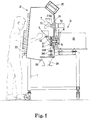
- Pulverizedmaterials smaller than the pore diameter of the screen 314 are quickly discharged from the discharge chute 241 through the discharge tube 240 accompanied with air flows in accordance with rotation of the impact pins 313a, separated into an air flow and pulverized materials by a bag filter that is continuously provided on the upper surface of the discharge chute 241 and is not shown, and the air flow is exhausted into the clean box 2 and the pulverized materials are collected by the collector that is not shown.
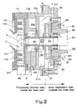
- a disk-shaped oil thrower 326 is attached and sandwiched between the collars 324a and 324b.
- gas supply lines are joined with the gas supply passages 610, 620
- gas exhaust lines are joined with the gas exhaust passages 612, 622
- flow rate adjusting valves are continuously provided in the middle of the gas exhaust lines
- filters are continuously provided at the front ends of the exhaust lines although these are not shown.
- the rotor 313 is rotated at a predetermined speed.
- the internal pressure of the processing chamber (central portion) 31 of the particle processing apparatus changes depending on the structure of the processing chamber 31 in accordance with the processing apparatus, the shape of the rotor 313, and the speed of rotation of the rotor 313.
- the gas inside the processing chamber 31 is ejected into the annular groove 611a through the shaft sealing gap formed between the collar 325 and the casing 312a, and in a case where the internal pressure is negative, contrary to the former case, the gas inside the annular groove 611a is suctioned to the processing chamber 31 side through said gap.
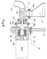
- the sealing gas circulating path can be vertically divided so that the seal boxes 63 and 64 are exposed by removing the casing 312b, isolation from the outside can be secured by the seal boxes 63 and 64, and even when the shaft sealing means 6 and the oil seal 323 are disposed in proximity to each other, the oil seal 323 is prevented from being directly exposed to the outside, and also, when cleaning the inside of the clean box 2, the oil seal 323 is protected and entering of a cleaning liquid is prevented.
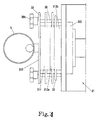
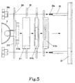
- the engaging arm 33 of the casing 312b is smaller than those of other components including the front cover 310. Therefore even when the engaging arm 33 of the adjacent casing 312a that has a relatively narrow width is disposed in proximity, the arms are easily held and operated. As a result the structure prevents operator's fingers from being caught between the engaging arms 33 and 33.
- the invention relates to a particle processing apparatus 3 structured so that, via an outer wall composing a clean box, a particle processing chamber is disposed inside the box and a drive mechanism including a drive rotary body is disposed outside the box, a drive rotary body 320 of the drive mechanism 32 is inserted into the particle processing chamber 31 via a shaft sealing means 6, and a rotor 313 interlocked and rotatably joined with the drive rotary body 320 is provided, wherein the shaft sealing means 6 is composed of a first shaft sealing means 61 for restraining particles to be processed in the particle processing chamber 31 from entering the drive mechanism 32 side and a second shaft sealing means 62 provided between the first shaft sealing means 61 and the drive mechanism 32, the second shaft sealing means 62 allows entering of particles from the first shaft sealing means 61 and entering of foreign matter from the drive mechanism 32 side thereby restrains entering of the particles to the drive mechanism 32 side and entering of the foreign matter to the first shaft sealing means 61 side.
Landscapes
- Engineering & Computer Science (AREA)
- Food Science & Technology (AREA)
- Health & Medical Sciences (AREA)
- Clinical Laboratory Science (AREA)
- Chemical & Material Sciences (AREA)
- Chemical Kinetics & Catalysis (AREA)
- Crushing And Pulverization Processes (AREA)
- Cleaning By Liquid Or Steam (AREA)
- Mechanical Treatment Of Semiconductor (AREA)
- Glanulating (AREA)
- Filling Or Emptying Of Bunkers, Hoppers, And Tanks (AREA)
- Developing Agents For Electrophotography (AREA)
- Agricultural Chemicals And Associated Chemicals (AREA)
- Processing And Handling Of Plastics And Other Materials For Molding In General (AREA)
- Photoreceptors In Electrophotography (AREA)
- Polarising Elements (AREA)
- Control And Other Processes For Unpacking Of Materials (AREA)
Abstract
Description
Claims (23)
- A particle processing apparatus comprising a particle processing chamber disposed inside a clean box and a drive mechanism including a drive rotary body disposed outside the clean box via an outer wall composing the clean box, said drive rotary body connected to a rotor provided inside the processing chamber, characterized in that the clean box is attached to a base on which the drive mechanism is installed, a sealing means fitted to the outer wall at a fitting portion of the rotary body so that sealing performance inside and outside the box is maintained from the outside of the outer wall, the processing chamber provided in close contact with the outer wall via a casing disposed inside the clean box so as to be integrated with the clean box and the sealing means, and structured so as to be disassembled inside the box.
- The particle processing apparatus according to claim 1, characterized in that a sealing gas circulating path for supply and exhaust of a sealing gas is formed between opposing surfaces of the sealing means and the processing chamber, the circulating path formed as a shaft sealing means for restraining particles to be processed by the rotor from entering the drive mechanism side, and the sealing means commonly used as a component of this shaft sealing means.
- The particle processing apparatus according to claim 2, characterized in that the sealing gas circulating path is formed across the inside and the outside of the clean box so as to be dividable into the processing chamber side and the drive mechanism side.
- The particle processing apparatus according to claim 2 or 3, characterized in that the sealing gas circulating path is formed so as to be vertically dividable so that the sealing means is exposed when the processing chamber is disassembled.
- The particle processing apparatus according to claim 2, 3 or 4, characterized in that said shaft sealing means is defined as a first shaft sealing means, and at the drive mechanism side of the sealing means, provided a second shaft sealing means for restraining a lubricating oil at the bearing from entering the first shaft sealing means side from the oil sealing means provided at the drive mechanism.
- A particle processing apparatus comprising a particle processing chamber disposed inside a clean box and a drive mechanism including a drive rotary body disposed outside the clean box via an outer wall composing the clean box, said drive rotary body of the drive mechanism fitted into the particle processing chamber via a shaft sealing means, a rotor provided inside the particle processing chamber rotatably connected to said drive rotary body, characterized in that the shaft sealing means is composed of a first shaft sealing means for restraining particles to be processed in the particle processing chamber from entering the drive mechanism side, a second shaft sealing means provided between the first shaft sealing means and the drive mechanism, said second shaft sealing means allowing particles from the first shaft sealing means and foreign substances from the drive mechanism side to enter the second shaft sealing means, thereby restraining the particles from entering the drive mechanism side and foreign substances from entering the first shaft sealing means side.
- The particle processing apparatus according to claim 6, characterized in that said drive mechanism is provided with a predetermined oil sealing means, the foreign substances from the drive mechanism side being a lubricating oil at the bearing in the drive mechanism.
- The particle processing apparatus according to claim 2, 3, 4, 5, 6 or 7, characterized in that each of the shaft sealing means is composed of a sealing gas circulating path for supply and exhaust of a sealing gas, which is independently formed.
- The particle processing apparatus according to claim 5, 6, 7 or 8, characterized in that the first shaft sealing means and the second shaft sealing means are communicated with each other via a shaft sealing gap between the drive rotary body and seal boxes, the second shaft sealing means being set to have a pressure lower than a sealing gas pressure of the first shaft sealing means so as to allow entering of a sealing gas from the first shaft sealing means through said shaft sealing gap.
- A particle processing apparatus which is divided into a particle processing chamber side disposed inside a clean box and a drive mechanism side disposed outside the clean box by an outer wall composing the clean box, and divided into the particle processing chamber side and the drive mechanism side via a predetermined attaching structure such as a base, a casing, a frame or the like, characterized in that in order to assembly and disassembly attach optional components such as a casing, a stator, a front cover and the like provided at the processing chamber side to the attaching structure in a multi-layered manner, a pair of supporting members having tightening means at the front ends are supported on the attaching structure in cantilever manner, said respective components provided with engaging arms to hang the supporting members, said components structured so as to be capable of assembly and disassembly by supporting and fixing the engaging arms to the supporting members by using the tightening means.
- The particle processing apparatus according to claim 10, characterized in that the components are coaxially supported by the supporting members.
- The particle processing apparatus according to claim 10 or 11, characterized in that the attaching structure is the outer wall composing the clean box.
- The particle processing apparatus according to claim 10, 11 or 12, characterized in that the supporting members are columnar rods.
- The particle processing apparatus according to claim 10, 11, 12 or 13, characterized in that in order to support the engaging arms on the supporting members, downward concave grooves formed in the engaging arms are fitted over the supportingmembers, the components structured so as tobe capable of assembly and disassembly in optional postures in optional upward directions from the axial line directions with respect to the supporting members.
- The particle processing apparatus according to claim 10, 11, 12, 13 or 14, characterized in that the engaging arms are formed so as to be different in size between the front cover and other components and to be able to hold.
- A particle processing apparatus comprising a particle processing chamber disposed inside a clean box and a drive mechanism including a drive rotary body disposed outside the clean box via an outer wall composing the clean box, a rotor provided inside the processing chamber rotatably connected to said drive rotary body, said particle processing apparatus further comprising a material supply unit disposed in the clean box so as to supply quantitatively-controlled amount of a raw material constantly to the processing chamber, said material supply unit characterized in that it comprises a supply part and a drive part which are linked by a predetermined link means in a manner enabling them to unlink, an attaching hole for attachment of the supply unit formed in the outer wall above the location at which the processing chamber is disposed, said drive part attached to the outside of the attaching hole by being faced to the box inner side so as to form a link means to the supply part at the attaching hole portion, said supply part structured so as to be attachable to and detachable from the box inner side together with the link means.
- The material supply unit disposed in the clean box according to claim 16, characterized in that material supply to the processing chamber is carried out in such a selective manner that a raw material is supplied via the supply unit when a quantitatively-controlled amount supply is required, and is supplied directly from a first raw material hopper attached to the processing chamber when the quantitatively-controlled amount supply is not required.
- The material supply unit disposed in the clean box according to claim 17, characterized in that the supply unit is disposed at a predetermined space above the first rawmaterial hopper that is directly provided on the processing chamber so that a raw material from the supply unit is supplied to the processing chamber through the first raw material hopper.
- The material supply unit disposed in the clean box according to claim 17, characterized in that when a quantitatively-controlled amount supply is required, a second raw material hopper attached to the supply unit is used.
- The material supply unit disposed in the clean box according to claim 16, 17, 18 or 19, characterized in that the supply part is structured so as to be attachable to and detachable from an attaching member attached to the frame plate.
- The material supply unit disposed in the clean box according to claim 16, 17, 18, 19 or 20, characterized in that the inside and outside of the box are sealed by fitting a bracket composing the drive part to the attaching hole from the outside of the box, and the link means composed of a magnet coupling mechanism which achieves driven transmission due to the relationship between multi-polar inner magnet and outer magnet that are disposed across a partition that partitions the supply part side and the drive part side.
- The material supply unit disposed in the clean box according to claim 21, characterized in that the partition is integrally formed on the attaching member.
- The material supply unit disposed in the clean box according to claim 16, 17, 18, 19, 20, 21 or 22, characterized in that the supply part is composed of a screw feeder, said screw feeder conveying a raw material supplied to the second raw material hopper, to the processing chamber.
Priority Applications (1)
| Application Number | Priority Date | Filing Date | Title |
|---|---|---|---|
| EP05077037A EP1623765B1 (en) | 2000-05-22 | 2001-05-21 | Particle processing apparatus |
Applications Claiming Priority (7)
| Application Number | Priority Date | Filing Date | Title |
|---|---|---|---|
| JP2000149986 | 2000-05-22 | ||
| JP2000149986A JP3709497B2 (en) | 2000-05-22 | 2000-05-22 | Powder processing equipment |
| JP2000177619A JP3475395B2 (en) | 2000-06-13 | 2000-06-13 | Powder processing equipment |
| JP2000177619 | 2000-06-13 | ||
| JP2000403274 | 2000-12-28 | ||
| JP2000403274A JP3443774B2 (en) | 2000-12-28 | 2000-12-28 | Material supply device for clean box |
| PCT/JP2001/004233 WO2001089701A1 (en) | 2000-05-22 | 2001-05-21 | Powder processing unit |
Related Child Applications (1)
| Application Number | Title | Priority Date | Filing Date |
|---|---|---|---|
| EP05077037A Division EP1623765B1 (en) | 2000-05-22 | 2001-05-21 | Particle processing apparatus |
Publications (3)
| Publication Number | Publication Date |
|---|---|
| EP1300195A1 true EP1300195A1 (en) | 2003-04-09 |
| EP1300195A4 EP1300195A4 (en) | 2004-03-10 |
| EP1300195B1 EP1300195B1 (en) | 2007-10-31 |
Family
ID=27343454
Family Applications (2)
| Application Number | Title | Priority Date | Filing Date |
|---|---|---|---|
| EP01932172A Expired - Lifetime EP1300195B1 (en) | 2000-05-22 | 2001-05-21 | Powder processing unit |
| EP05077037A Expired - Lifetime EP1623765B1 (en) | 2000-05-22 | 2001-05-21 | Particle processing apparatus |
Family Applications After (1)
| Application Number | Title | Priority Date | Filing Date |
|---|---|---|---|
| EP05077037A Expired - Lifetime EP1623765B1 (en) | 2000-05-22 | 2001-05-21 | Particle processing apparatus |
Country Status (6)
| Country | Link |
|---|---|
| US (1) | US6905085B2 (en) |
| EP (2) | EP1300195B1 (en) |
| AT (2) | ATE410234T1 (en) |
| AU (1) | AU2001258789A1 (en) |
| DE (2) | DE60131173T2 (en) |
| WO (1) | WO2001089701A1 (en) |
Cited By (5)
| Publication number | Priority date | Publication date | Assignee | Title |
|---|---|---|---|---|
| WO2004062808A1 (en) * | 2003-01-15 | 2004-07-29 | Fractivator Oy | Method and device for disintegration of organic material and use of the device |
| DE102006021195A1 (en) * | 2006-05-06 | 2007-11-15 | Hosokawa Alpine Ag | Plant with at least one mill or sifter has externally sealed enclosure common to all plant components provided with no rotary transmission leadthroughs, wherein rotating working part is driven by magnetic bearing spindle drive |
| US7863788B2 (en) | 2006-05-06 | 2011-01-04 | Hosokawa Alpine Aktiengesellschaft | System concept for mills and classifiers with magnetic bearing spindle drives |
| EP2789394A3 (en) * | 2013-04-13 | 2014-12-17 | HOSOKAWA ALPINE Aktiengesellschaft | Processing machine for installation in a wall |
| CN111575185A (en) * | 2020-05-25 | 2020-08-25 | 海口健康岛生物科技有限公司 | Automatic device for living cell culture |
Families Citing this family (8)
| Publication number | Priority date | Publication date | Assignee | Title |
|---|---|---|---|---|
| JPS6180324A (en) * | 1984-09-26 | 1986-04-23 | Ricoh Co Ltd | Coordinate input method |
| DE202010008197U1 (en) | 1997-10-28 | 2011-02-10 | Kulakov, Igor A. | Centrifugal jet mill |
| FI124439B (en) * | 2009-01-14 | 2014-08-29 | Fractivator Oy | repulsion Mill |
| CN101811080A (en) * | 2010-05-04 | 2010-08-25 | 李晓文 | Energy-saving split-combined type pulverizer |
| JP6124585B2 (en) * | 2012-12-26 | 2017-05-10 | 株式会社アーステクニカ | Powder processing equipment |
| EP3986602A4 (en) * | 2019-06-19 | 2023-08-02 | Merck Sharp & Dohme LLC | Containment system for mixing dry powders with solvents during drug production or processing |
| CN112207020B (en) * | 2020-09-08 | 2022-08-19 | 广东顺德百涂通智能科技有限公司 | Pressure-bearing type washing screening machine |
| CN116726783B (en) * | 2023-08-11 | 2023-11-03 | 菏泽昌盛源科技股份有限公司 | Cleaning and drying device for chemical product production equipment |
Family Cites Families (10)
| Publication number | Priority date | Publication date | Assignee | Title |
|---|---|---|---|---|
| DE3244362A1 (en) * | 1982-12-01 | 1984-06-07 | Deutsche Babcock Werke AG, 4200 Oberhausen | DEVICE FOR SEALING THE INSIDE OF A MILL |
| US4524917A (en) * | 1983-03-03 | 1985-06-25 | Williams Patent Crusher And Pulverizer Company | Air seal and lubrication system for roller grinding mills |
| US4480923A (en) * | 1983-09-14 | 1984-11-06 | Usm Corporation | Rotary processors and seals |
| JPS61283361A (en) * | 1985-06-05 | 1986-12-13 | 株式会社 奈良機械製作所 | Impact crusher |
| JPH0533823U (en) | 1991-10-16 | 1993-05-07 | 株式会社フクハラ | Bacteria removal device in air compressor |
| DE4207341C1 (en) | 1992-03-09 | 1993-07-15 | Acr Automation In Cleanroom Gmbh, 7732 Niedereschach, De | |
| JP3053972B2 (en) | 1992-08-07 | 2000-06-19 | 株式会社奈良機械製作所 | Powder processing equipment |
| IT1256356B (en) | 1992-08-31 | 1995-12-01 | DEVICE FOR FEEDING SAMPLES TO ELEMENTARY ANALYSIS EQUIPMENT | |
| DE4307083B4 (en) * | 1993-03-06 | 2007-07-12 | Zoz Maschinenbau Gmbh | Device for fine grinding of solids |
| JPH07528U (en) * | 1993-05-28 | 1995-01-06 | 不二パウダル株式会社 | Pulverizer |
-
2001
- 2001-05-21 AT AT05077037T patent/ATE410234T1/en not_active IP Right Cessation
- 2001-05-21 AT AT01932172T patent/ATE376884T1/en not_active IP Right Cessation
- 2001-05-21 AU AU2001258789A patent/AU2001258789A1/en not_active Abandoned
- 2001-05-21 DE DE60131173T patent/DE60131173T2/en not_active Expired - Lifetime
- 2001-05-21 EP EP01932172A patent/EP1300195B1/en not_active Expired - Lifetime
- 2001-05-21 WO PCT/JP2001/004233 patent/WO2001089701A1/en not_active Ceased
- 2001-05-21 US US10/276,980 patent/US6905085B2/en not_active Expired - Lifetime
- 2001-05-21 EP EP05077037A patent/EP1623765B1/en not_active Expired - Lifetime
- 2001-05-21 DE DE60136111T patent/DE60136111D1/en not_active Expired - Lifetime
Cited By (7)
| Publication number | Priority date | Publication date | Assignee | Title |
|---|---|---|---|---|
| WO2004062808A1 (en) * | 2003-01-15 | 2004-07-29 | Fractivator Oy | Method and device for disintegration of organic material and use of the device |
| US7314190B2 (en) | 2003-01-15 | 2008-01-01 | Fractivator Oy | Method and device for disintegration of organic material and use of the device |
| DE102006021195A1 (en) * | 2006-05-06 | 2007-11-15 | Hosokawa Alpine Ag | Plant with at least one mill or sifter has externally sealed enclosure common to all plant components provided with no rotary transmission leadthroughs, wherein rotating working part is driven by magnetic bearing spindle drive |
| US7863788B2 (en) | 2006-05-06 | 2011-01-04 | Hosokawa Alpine Aktiengesellschaft | System concept for mills and classifiers with magnetic bearing spindle drives |
| DE102006021195B4 (en) * | 2006-05-06 | 2014-03-13 | Hosokawa Alpine Ag | Plant concept for mills or classifiers |
| EP2789394A3 (en) * | 2013-04-13 | 2014-12-17 | HOSOKAWA ALPINE Aktiengesellschaft | Processing machine for installation in a wall |
| CN111575185A (en) * | 2020-05-25 | 2020-08-25 | 海口健康岛生物科技有限公司 | Automatic device for living cell culture |
Also Published As
| Publication number | Publication date |
|---|---|
| WO2001089701A1 (en) | 2001-11-29 |
| US20030106951A1 (en) | 2003-06-12 |
| DE60131173D1 (en) | 2007-12-13 |
| EP1623765A1 (en) | 2006-02-08 |
| EP1300195A4 (en) | 2004-03-10 |
| AU2001258789A1 (en) | 2001-12-03 |
| EP1623765B1 (en) | 2008-10-08 |
| EP1300195B1 (en) | 2007-10-31 |
| DE60131173T2 (en) | 2008-11-27 |
| DE60136111D1 (en) | 2008-11-20 |
| ATE410234T1 (en) | 2008-10-15 |
| US6905085B2 (en) | 2005-06-14 |
| ATE376884T1 (en) | 2007-11-15 |
Similar Documents
| Publication | Publication Date | Title |
|---|---|---|
| EP1300195B1 (en) | Powder processing unit | |
| US9114400B2 (en) | Grinding type vertical grain milling machine | |
| US7883039B2 (en) | Continuous granulating and drying apparatus including measurement units | |
| US4073444A (en) | Cutting mill | |
| US6543710B2 (en) | Separator mill | |
| US4829893A (en) | Cereal-grain polishing apparatus | |
| WO2021051436A1 (en) | Automatic grain milling apparatus | |
| JP2002045676A (en) | Equipment and method for quasi-continuous processing of particulate material | |
| EP2134458A2 (en) | Continuous granulating and drying apparatus including measurement units and method of continuous granulation and drying | |
| JP3502661B2 (en) | Continuous water mixing equipment | |
| JP2002200431A (en) | Material supply device for clean box | |
| JP2001327892A (en) | Granule treating device | |
| CN115738895B (en) | A highly enclosed small-batch integrated pharmaceutical system | |
| JP2001129419A (en) | Pulverizer | |
| JP4402476B2 (en) | Crusher | |
| CN112439511B (en) | Ball mill workshop | |
| JP2001353447A (en) | Powder material treatment device | |
| JP3644478B2 (en) | Crusher | |
| CN215542544U (en) | Feed premix device | |
| CN218890620U (en) | Fruit paste grinding machine | |
| KR200305817Y1 (en) | A Discharging Unit for Grain Pulverizer with an Air Distributor | |
| CN217725382U (en) | High-efficient feed mixer | |
| CN111841783A (en) | Stirring tank for sesame paste production and manufacturing method | |
| CA1282665C (en) | Cereal-grain polishing apparatus | |
| JP3471680B2 (en) | Wrapping machine |
Legal Events
| Date | Code | Title | Description |
|---|---|---|---|
| PUAI | Public reference made under article 153(3) epc to a published international application that has entered the european phase |
Free format text: ORIGINAL CODE: 0009012 |
|
| 17P | Request for examination filed |
Effective date: 20021128 |
|
| AK | Designated contracting states |
Kind code of ref document: A1 Designated state(s): AT BE CH CY DE DK ES FI FR GB GR IE IT LI LU MC NL PT SE TR |
|
| AX | Request for extension of the european patent |
Extension state: AL LT LV MK RO SI |
|
| RIC1 | Information provided on ipc code assigned before grant |
Ipc: 7F 24F 7/06 B Ipc: 7B 01L 1/00 B Ipc: 7B 02C 23/00 A Ipc: 7B 02C 23/04 B Ipc: 7B 01L 1/04 B Ipc: 7B 02C 13/22 B |
|
| A4 | Supplementary search report drawn up and despatched |
Effective date: 20040126 |
|
| 17Q | First examination report despatched |
Effective date: 20050420 |
|
| GRAP | Despatch of communication of intention to grant a patent |
Free format text: ORIGINAL CODE: EPIDOSNIGR1 |
|
| GRAS | Grant fee paid |
Free format text: ORIGINAL CODE: EPIDOSNIGR3 |
|
| GRAA | (expected) grant |
Free format text: ORIGINAL CODE: 0009210 |
|
| AK | Designated contracting states |
Kind code of ref document: B1 Designated state(s): AT BE CH CY DE DK ES FI FR GB GR IE IT LI LU MC NL PT SE TR |
|
| REG | Reference to a national code |
Ref country code: GB Ref legal event code: FG4D |
|
| REG | Reference to a national code |
Ref country code: IE Ref legal event code: FG4D |
|
| REG | Reference to a national code |
Ref country code: CH Ref legal event code: EP |
|
| REF | Corresponds to: |
Ref document number: 60131173 Country of ref document: DE Date of ref document: 20071213 Kind code of ref document: P |
|
| NLV1 | Nl: lapsed or annulled due to failure to fulfill the requirements of art. 29p and 29m of the patents act | ||
| PG25 | Lapsed in a contracting state [announced via postgrant information from national office to epo] |
Ref country code: ES Free format text: LAPSE BECAUSE OF FAILURE TO SUBMIT A TRANSLATION OF THE DESCRIPTION OR TO PAY THE FEE WITHIN THE PRESCRIBED TIME-LIMIT Effective date: 20080211 Ref country code: CH Free format text: LAPSE BECAUSE OF FAILURE TO SUBMIT A TRANSLATION OF THE DESCRIPTION OR TO PAY THE FEE WITHIN THE PRESCRIBED TIME-LIMIT Effective date: 20071031 Ref country code: NL Free format text: LAPSE BECAUSE OF FAILURE TO SUBMIT A TRANSLATION OF THE DESCRIPTION OR TO PAY THE FEE WITHIN THE PRESCRIBED TIME-LIMIT Effective date: 20071031 Ref country code: SE Free format text: LAPSE BECAUSE OF FAILURE TO SUBMIT A TRANSLATION OF THE DESCRIPTION OR TO PAY THE FEE WITHIN THE PRESCRIBED TIME-LIMIT Effective date: 20080131 Ref country code: LI Free format text: LAPSE BECAUSE OF FAILURE TO SUBMIT A TRANSLATION OF THE DESCRIPTION OR TO PAY THE FEE WITHIN THE PRESCRIBED TIME-LIMIT Effective date: 20071031 |
|
| REG | Reference to a national code |
Ref country code: CH Ref legal event code: PL |
|
| PG25 | Lapsed in a contracting state [announced via postgrant information from national office to epo] |
Ref country code: PT Free format text: LAPSE BECAUSE OF FAILURE TO SUBMIT A TRANSLATION OF THE DESCRIPTION OR TO PAY THE FEE WITHIN THE PRESCRIBED TIME-LIMIT Effective date: 20080331 |
|
| PG25 | Lapsed in a contracting state [announced via postgrant information from national office to epo] |
Ref country code: AT Free format text: LAPSE BECAUSE OF FAILURE TO SUBMIT A TRANSLATION OF THE DESCRIPTION OR TO PAY THE FEE WITHIN THE PRESCRIBED TIME-LIMIT Effective date: 20071031 |
|
| PG25 | Lapsed in a contracting state [announced via postgrant information from national office to epo] |
Ref country code: DK Free format text: LAPSE BECAUSE OF FAILURE TO SUBMIT A TRANSLATION OF THE DESCRIPTION OR TO PAY THE FEE WITHIN THE PRESCRIBED TIME-LIMIT Effective date: 20071031 |
|
| EN | Fr: translation not filed | ||
| PG25 | Lapsed in a contracting state [announced via postgrant information from national office to epo] |
Ref country code: BE Free format text: LAPSE BECAUSE OF FAILURE TO SUBMIT A TRANSLATION OF THE DESCRIPTION OR TO PAY THE FEE WITHIN THE PRESCRIBED TIME-LIMIT Effective date: 20071031 |
|
| PLBE | No opposition filed within time limit |
Free format text: ORIGINAL CODE: 0009261 |
|
| STAA | Information on the status of an ep patent application or granted ep patent |
Free format text: STATUS: NO OPPOSITION FILED WITHIN TIME LIMIT |
|
| 26N | No opposition filed |
Effective date: 20080801 |
|
| PG25 | Lapsed in a contracting state [announced via postgrant information from national office to epo] |
Ref country code: FR Free format text: LAPSE BECAUSE OF FAILURE TO SUBMIT A TRANSLATION OF THE DESCRIPTION OR TO PAY THE FEE WITHIN THE PRESCRIBED TIME-LIMIT Effective date: 20080704 |
|
| PG25 | Lapsed in a contracting state [announced via postgrant information from national office to epo] |
Ref country code: MC Free format text: LAPSE BECAUSE OF NON-PAYMENT OF DUE FEES Effective date: 20080531 |
|
| PG25 | Lapsed in a contracting state [announced via postgrant information from national office to epo] |
Ref country code: GR Free format text: LAPSE BECAUSE OF FAILURE TO SUBMIT A TRANSLATION OF THE DESCRIPTION OR TO PAY THE FEE WITHIN THE PRESCRIBED TIME-LIMIT Effective date: 20080201 |
|
| PG25 | Lapsed in a contracting state [announced via postgrant information from national office to epo] |
Ref country code: FI Free format text: LAPSE BECAUSE OF FAILURE TO SUBMIT A TRANSLATION OF THE DESCRIPTION OR TO PAY THE FEE WITHIN THE PRESCRIBED TIME-LIMIT Effective date: 20071031 |
|
| PG25 | Lapsed in a contracting state [announced via postgrant information from national office to epo] |
Ref country code: IE Free format text: LAPSE BECAUSE OF NON-PAYMENT OF DUE FEES Effective date: 20080521 |
|
| PG25 | Lapsed in a contracting state [announced via postgrant information from national office to epo] |
Ref country code: CY Free format text: LAPSE BECAUSE OF FAILURE TO SUBMIT A TRANSLATION OF THE DESCRIPTION OR TO PAY THE FEE WITHIN THE PRESCRIBED TIME-LIMIT Effective date: 20071031 |
|
| PG25 | Lapsed in a contracting state [announced via postgrant information from national office to epo] |
Ref country code: LU Free format text: LAPSE BECAUSE OF NON-PAYMENT OF DUE FEES Effective date: 20080521 |
|
| PG25 | Lapsed in a contracting state [announced via postgrant information from national office to epo] |
Ref country code: TR Free format text: LAPSE BECAUSE OF FAILURE TO SUBMIT A TRANSLATION OF THE DESCRIPTION OR TO PAY THE FEE WITHIN THE PRESCRIBED TIME-LIMIT Effective date: 20071031 |
|
| PG25 | Lapsed in a contracting state [announced via postgrant information from national office to epo] |
Ref country code: IT Free format text: LAPSE BECAUSE OF NON-PAYMENT OF DUE FEES Effective date: 20080531 |
|
| PGFP | Annual fee paid to national office [announced via postgrant information from national office to epo] |
Ref country code: DE Payment date: 20200529 Year of fee payment: 20 |
|
| PGFP | Annual fee paid to national office [announced via postgrant information from national office to epo] |
Ref country code: GB Payment date: 20200529 Year of fee payment: 20 |
|
| REG | Reference to a national code |
Ref country code: DE Ref legal event code: R071 Ref document number: 60131173 Country of ref document: DE |
|
| REG | Reference to a national code |
Ref country code: GB Ref legal event code: PE20 Expiry date: 20210520 |
|
| PG25 | Lapsed in a contracting state [announced via postgrant information from national office to epo] |
Ref country code: GB Free format text: LAPSE BECAUSE OF EXPIRATION OF PROTECTION Effective date: 20210520 |