EP1300266A2 - Verfahren zur scheibenbeschlagverhindernden Wärmepumpenleistungsregelung einer Fahrzeug-Klimaanlage - Google Patents
Verfahren zur scheibenbeschlagverhindernden Wärmepumpenleistungsregelung einer Fahrzeug-Klimaanlage Download PDFInfo
- Publication number
- EP1300266A2 EP1300266A2 EP02018879A EP02018879A EP1300266A2 EP 1300266 A2 EP1300266 A2 EP 1300266A2 EP 02018879 A EP02018879 A EP 02018879A EP 02018879 A EP02018879 A EP 02018879A EP 1300266 A2 EP1300266 A2 EP 1300266A2
- Authority
- EP
- European Patent Office
- Prior art keywords
- air
- heat exchanger
- air flow
- determined
- heat pump
- Prior art date
- Legal status (The legal status is an assumption and is not a legal conclusion. Google has not performed a legal analysis and makes no representation as to the accuracy of the status listed.)
- Granted
Links
Images

Classifications
-
- B—PERFORMING OPERATIONS; TRANSPORTING
- B60—VEHICLES IN GENERAL
- B60H—ARRANGEMENTS OF HEATING, COOLING, VENTILATING OR OTHER AIR-TREATING DEVICES SPECIALLY ADAPTED FOR PASSENGER OR GOODS SPACES OF VEHICLES
- B60H1/00—Heating, cooling or ventilating devices
- B60H1/32—Cooling devices
- B60H1/3204—Cooling devices using compression
- B60H1/3205—Control means therefor
- B60H1/3207—Control means therefor for minimizing the humidity of the air
-
- B—PERFORMING OPERATIONS; TRANSPORTING
- B60—VEHICLES IN GENERAL
- B60H—ARRANGEMENTS OF HEATING, COOLING, VENTILATING OR OTHER AIR-TREATING DEVICES SPECIALLY ADAPTED FOR PASSENGER OR GOODS SPACES OF VEHICLES
- B60H1/00—Heating, cooling or ventilating devices
- B60H1/00642—Control systems or circuits; Control members or indication devices for heating, cooling or ventilating devices
- B60H1/00735—Control systems or circuits characterised by their input, i.e. by the detection, measurement or calculation of particular conditions, e.g. signal treatment, dynamic models
- B60H1/00785—Control systems or circuits characterised by their input, i.e. by the detection, measurement or calculation of particular conditions, e.g. signal treatment, dynamic models by the detection of humidity or frost
Definitions
- the invention relates to a method for disc fitting Heat pump power control, optionally in cooling mode and heat pump mode operable vehicle air conditioning, the one in the cooling mode of operation as an evaporator for air flow cooling and in heat pump mode as a condenser / gas cooler Having operated for air flow heating heat exchanger.
- Vehicle air conditioning systems of this type in which a heat exchanger in the Cooling mode as evaporator and in heat pump mode as Condenser / gas cooler functions, allow a cost-effective Heat pump operation in addition to the cooling operation, which is increasingly for Motor vehicles are used at the lowest possible fuel consumption are designed and where therefore the heating power through the waste heat of the drive motor for a comfortable interior heating no longer sufficient.
- the published patent application EP 1 078 788 A2 discloses a method for disc fitting Heat pump power control of the beginning described type in which the dew point of the Air flow after exiting from the cooling mode as an evaporator and operated in heat pump mode as a condenser / gas cooler Heat exchanger by measuring the temperature and humidity this outlet air flow determined by means of appropriate sensors becomes.
- a direct measurement of the dew point temperature be provided by means of a suitable sensor.
- the windshield temperature is measured or indirectly Measurements of the outside temperature, the interior temperature and the Vehicle speed determined.
- the heat pump operation then becomes regulated to a set value of the dew point temperature of the outlet air flow, which is equal to the windscreen temperature.
- the invention is a technical problem to provide a method based on the type mentioned, with which the heat pump performance the air conditioning in particular in situations where the working in the heat pump mode as a condenser / gas cooler Heat exchanger due to its evaporator function in a previous Cooling operation interval is still wet, optimally so regulated is that on the one hand the highest possible heat pump performance set for rapid heating of the vehicle interior, on the other hand but disc fitting is reliably prevented.
- the invention solves this problem by providing a method for disc fitting preventing heat pump power control with the features of claim 1, 4 or 5.
- the heat pump power in the initial heat pump mode regulated to an air temperature set point of the outlet air flow, the to a value less than or equal to the sum of the determined Outside temperature of the air flow and an offset value set which, depending on the guided over the heat exchanger Air quantity is variably specified. This takes into account the the air volume dependent conditions in the material and heat transfer in the participating heat exchangers and the tendency to mist the discs, allowing a maximum possible heat pump performance set at otherwise the same conditions and thus the drying time be shortened for the initially wet heat exchanger can.
- the offset value in addition depending on a disk heating value given the progressive heating of the disk by the heated Air flow considered and this as a time integral over a Windscreen warm-up power parameters calculated in dependence from the determined outside temperature value, from a determined outlet temperature value the air flow and the amount of air is determined.
- functional dependencies can e.g. determined empirically and as appropriate characteristics or maps are stored.
- this method is according to claim 3 at known condensation load of the heat exchanger of the disk warm-up performance parameters additionally depending on this Condensation charge determined. This takes into account the influence of a Uneven drying of the heat exchanger.
- the method of claim 4 and the method of claim 5 are suitable for air conditioning systems where the outlet water content of the Air flow after exiting the heat exchanger, e.g. through use an air humidity sensor can be monitored, which is a direct Control of the outlet water content of the from the heat exchanger exiting air flow allows.
- the heat pump performance to a water content setpoint of the airflow after exiting the heat exchanger regulated to a value less than or equal to the sum of a determined saturation water content value the airflow at ambient temperature and a water content offset value is given, which depends on the over the Heat exchanger conducted air quantity is variably specified.
- This takes into account the conditions in the mass transfer and heat transfer in the participating heat exchangers and the misting tendency of the Slices.
- the exact functional dependence can e.g. empirically determined and stored as a characteristic.
- the amount of air can be for this Method as well as for the method according to claims 1 to 3 in conventional manner e.g. based on recorded air blower and Air damper settings and the driving speed are determined.
- the water content setpoint no more than a water content value, which is the progressive one Disk heating by a temperature offset value according to the type of The method according to claim 2 taken into account.
- the vehicle air conditioning system shown schematically in FIG. 1 has a refrigerant circuit of conventional design which operates with the refrigerant CO 2 or another conventional refrigerant, and is designed so that the air conditioner is selectively operable in the cooling operation mode and the heat pump mode.
- the main components are a compressor 1, an external heat exchanger 2, ie an external air flow 3, an expansion element 4, an internal heat exchanger 6, with an associated air conveying fan 7, a 4/2-way valve, which is supplied by an air conditioning air flow 5 directed into a vehicle interior 8 for switching the direction of the refrigerant flow when switching between cooling and heat pump operation, a collector 9 and in a conventional, not shown in detail manner of an engine coolant, for example water, through-flow, air-heating heat exchanger 10th
- the refrigerant flows in through an associated Arrow KB indicated direction, in heat pump mode in the to opposite, indicated by an associated arrow WB Direction.
- the outer heat exchanger 2 acts in the cooling mode as condenser / gas cooler and in heat pump mode as evaporator.
- the internal heat exchanger 6 acts in the Cooling mode as evaporator and in heat pump mode as condenser / gas cooler.
- it cools it in fresh air mode by the air conveyor fan 7 from the outside and in the recirculation mode from Vehicle interior 5 supplied airflow while he was in the Heat pump operation heated.
- the from the internal heat exchanger 6 conditioned air flow 5 is not shown, conventional Air ducts, flaps and outlet nozzles in the vehicle interior guided, depending on needs and system design on more Air conditioning components can be performed, in particular a Radiator.
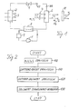
- FIG. 2 illustrates a variant of the method which manages without monitoring the air humidity or the water content of the air conditioning air flow 5 after exiting the heat exchanger 6.
- the heat pump capacity is limited in the initial heat pump operation with still wet heat exchanger 6 by regulating to a specially determined air temperature setpoint TN should the air flow 5 after exiting the heat exchanger 6.
- the air quantity m L conducted via the heat exchanger 6 is first of all determined for this purpose. This is done in a conventional manner and therefore not described here in detail on the basis of information about the blower stage of the air-conveying blower 7, the flap positions of the air-volume-influencing air flaps and the driving speed. Furthermore, the value of the outside temperature T A and the temperature values T N and T S for the air flow before entry into or out of the heat exchanger 10 through which the engine coolant flows are determined, for example, directly by corresponding temperature sensors.
- an air temperature offset value T O is determined (step 110).
- this offset value T O is determined solely as a function of the determined air quantity m L , wherein the functional dependency is determined beforehand empirically by tests and selection of the corresponding vehicle-specific function and stored as a corresponding characteristic curve. Even this, depending on the amount of air m L variable specification of the air temperature offset value T O allows compared to the specification of a constant air temperature offset value and even more compared to a method in which the air temperature setpoint without offset value is set to at most the outside temperature, a Increased heat pump performance and thus a shortened drying time for the heat exchanger without the risk of window fogging.
- the air temperature offset value T o is additionally predefined as a function of a window heating value S e , which describes the effect of the progressive heating of the window.
- This slice heating value is calculated as a time integral over a slice warm up power parameter that expresses the warming power delivered to the slices by the air conditioning air flow as a function of the detected outside temperature value T A , the determined exit temperature value T S and the determined air amount m L of the air conditioning air flow and, if applicable the leaves determine the air flow to the discs determining flap positions.
- the disk warm-up power parameter S I can be expressed as a function f (T A , T S , m I , damper position, t) of outside temperature T A , outlet temperature T S , air quantity m L , damper positions, and time t.
- the function f is again preferably determined empirically for the respective vehicle type and stored as a map.
- the air temperature offset value T o is then a function T o (m L , S e ) of the determined air quantity m L and the determined slice heating value S e , which represents the time integral over the slice warm-up power parameter S I.
- the air temperature setpoint TN is then to be fixed for the intenbetschverhindernde Heat pump power control to a value equal to the sum of the detected outdoor temperature value T A and the detected air temperature offset value T O or only slightly lower, ie TN should ⁇ T A + T O.
- the sum of external-temperature value T A and offset value T O a from the air temperature setpoint TN should be aimed at is upper limit for a maximum heat pump power adjustment for still safe suppressed fogging tendency.
- the air temperature setpoint becomes compared with a suitably predefinable threshold (Step 130).
- the threshold is chosen to be exceeded the conclusion of the air temperature setpoint, that the heat exchanger is dried, so from that point on the heat pump operation continued without power limitation can be.
- the condensate loading of the heat exchanger 6 is known (suitable estimation methods are described, for example, in a parallel German patent application of the Applicant (our file: P 40201 DE), which can be referred to), this information can be used to further optimize the heat pump power control.
- the Scheibenholz stiirmadosparameter S I is additionally determined in this case as a function of the instantaneous Kondenswasserbeladung the heat exchanger 6, wherein this dependence is again preferably empirically determined in advance by experiments and stored in the map for the Scheibenauficarm sosparameter S I.
- the condensate loading can be updated by estimating the amount of evaporated water.
- the estimate of the evaporated amount of water is based on the difference of a determined inlet water content of the air stream 5 before entering the heat exchanger 6 and a determined outlet water content of the same after exiting the heat exchanger 6 is possible (as in the mentioned parallel German patent application of the Applicant (our file : P 40 201 DE) described in detail).
- the means for detecting the humidity or the water content of the air conditioning 5 after exiting the heat exchanger 6, the moisture content of the air flowing to the discs can be controlled directly via a suitable Einregelung the outlet water content of the air flow, so that a very rapid, optimal drying of the heat exchanger 6 is possible without the restriction of the outlet air temperature of the process variant described in FIG. 2 is necessary.
- a method may be used in which the heat pump performance is controlled disc-preventing to a water content target value FN soll of the air-conditioning air flow 5 after exiting the heat exchanger 6 and will be explained below with reference to FIG.
- the required input variables of this method are firstly determined again, specifically the air quantity m L conducted via the heat exchanger 6, the outside air temperature T V and the outlet air temperature T S of the air flow after emerging from the heat exchanger 10 flowing through the coolant and the water content FV N at the exit from the internal, refrigerant-flow heat exchanger 6 (step 200).
- the determination of these variables takes place as in the corresponding step 100 in the method of FIG. 2, to which reference may be made.
- the water content desired value FN is then set to be equal to or slightly smaller than a value which is equal to the sum of an inlet water content saturation value FV S and a water content offset value FN 0 , ie this sum is an upper limit to which the water content target value FN should approach as close as possible in order to obtain a high heat pump performance with simultaneously suppressed Scheibenbeschlagneist.
- the water content offset value FN O is selected to be variable as a function of the air quantity m L , the associated functional dependency in turn preferably being determined empirically in advance by tests and stored as a corresponding characteristic curve.
- the inlet water content saturation value FV S denotes the water content of the air at the given outside temperature T A and an assumed maximum relative saturated air humidity of 100%.
- an even more precise method variant takes into account the effect of progressive heating of the disk.
- the wafer heating representing wafer heating value S e as a time integral over the disk warm-up performance parameters S I which describes the accommodated by the air-conditioning air stream 5 to the discs heat-up and depending on the outer Air temperature T A , the outlet air temperature T S , the amount of air m L , the relevant flap positions and the time t is determined, preferably again based on maps that are empirically obtained in advance by tests vehicle-specific (step 210).
- an air temperature offset value T O is determined as a map-based predefined function of the air quantity m L and the window heating value S e (step 220).
- the obtained air temperature offset value T O is added to the outside temperature value T A , and then the saturation water content value FV S (T A + T O ) which determines the water content of the air conditioning air flow at this sum temperature T A + T O in the case of Indicates 100% relative humidity.
- the water content set value FN to the air conditioning air stream 5 after emerging from the heat exchanger 6 is then set for the intenbetschverhindernde Heat pump power control on these determined saturation water content value FV S (T A + T O), or just below a value (step 230). This makes it possible to set the highest possible heat pump capacity without windshield fogging by condensate water evaporating from the heat exchanger 6 into the air stream 5.
- a further modification results when additional vehicle interior heating means be used, in particular those that the heat to the discs guided air conditioning airflow, such as a conventional, in the air conditioning housing of the air conditioner built-in PTC radiator. This is in the calculation of the Disk heating value to be considered.
Landscapes
- Physics & Mathematics (AREA)
- Thermal Sciences (AREA)
- Engineering & Computer Science (AREA)
- Mechanical Engineering (AREA)
- Air-Conditioning For Vehicles (AREA)
Abstract
Description
- Fig. 1
- ein schematisches Blockdiagramm einer erfindungsgemäß betreibbaren Fahrzeug-Klimaanlage,
- Fig. 2
- ein Flussdiagramm eines Verfahrens zur scheibenbeschlagverhindernden Wärmepumpenleistungsregelung auf einen vorgebbaren Lufttemperatur-Sollwert für die Klimaanlage von Fig. 1 und
- Fig. 3
- ein Flussdiagramm eines Verfahrens zur scheibenbeschlagverhindernden Wärmepumpenleistungsregelung auf einen vorgebbaren Wassergehalt-Sollwert für die Klimaanlage von Fig. 1.
Claims (5)
- Verfahren zur scheibenbeschlagverhindernden Wärmepumpenleistungsregelung einer wahlweise im Kühlbetriebsmodus und Wärmepumpenmodus betreibbaren Fahrzeug-Klimaanlage, die einen im Kühlbetriebsmodus als Verdampfer zur Luftstromkühlung und im Wärmepumpenmodus als Kondensator/Gaskühler zur Luftstromerwärmung betriebenen Wärmeübertrager (6) aufweist,
dadurch gekennzeichnet, dass
bei einsetzendem Wärmepumpenbetrieb und aufgrund eines vorhergehenden Kühlbetriebs noch nassem Wärmeübertrager (6) auf einen vorgebbaren Lufttemperatur-Sollwert (TNsoll) des Luftstroms (5) nach Austritt aus dem Wärmeübertrager (6) geregelt wird, der auf einen Wert gleich groß wie oder kleiner als die Summe (TA+TO) eines ermittelten Außen-Temperaturwertes (TA) des Luftstroms vor Eintritt in den Wärmeübertrager und eines Lufttemperatur-Offsetwertes (TO) festgesetzt wird, welcher in Abhängigkeit von einem ermittelten Luftmengenwert (mL) des über den Wärmeübertrager geleiteten Luftstroms variabel vorgegeben wird. - Verfahren nach Anspruch 1, weiter dadurch gekennzeichnet, dass der Lufttemperatur-Offsetwert (TO) zusätzlich in Abhängigkeit von einem die fortschreitende Scheibenerwärmung repräsentierenden Scheibenerwärmungswert (Se) vorgegeben wird, der als Zeitintegral über einen Scheibenaufwärmleistungsparameter (SI) berechnet wird, welcher in Abhängigkeit vom ermittelten Außen-Temperaturwert (TA), einem ermittelten Austritts-Temperaturwert (TS) des Luftstroms und der ermittelten Luftmenge (mL) bestimmt wird.
- Verfahren nach Anspruch 2, weiter dadurch gekennzeichnet, dass der Scheibenaufwärmleistungsparameter (SI) zusätzlich in Abhängigkeit von einem ermittelten Kondenswasserbeladungswert bestimmt wird, der die Menge an am Wärmeübertrager kondensiertem Wasser beschreibt.
- Verfahren zur scheibenbeschlagverhindernden Wärmepumpenleistungsregelung einer wahlweise im Kühlbetriebsmodus und Wärmepumpenmodus betreibbaren Fahrzeug-Klimaanlage, die einen im Kühlbetriebsmodus als Verdampfer zur Luftstromkühlung und im Wärmepumpenmodus als Kondensator/Gaskühler zur Luftstromerwärmung betriebenen Wärmeübertrager (6) aufweist,
dadurch gekennzeichnet, dass
bei einsetzendem Wärmepumpenbetrieb und aufgrund eines vorhergehenden Kühlbetriebs noch nassem Wärmeübertrager (6) auf einen Wassergehalt-Sollwert (FNsoll) des Luftstroms (5) nach Austritt aus dem Wärmeübertrager geregelt wird, der auf einen Wert gleich groß wie oder kleiner als die Summe (FVS+FNO) eines Wassergehaltswertes (FVS(TA)), welcher den Wassergehalt des Luftstroms bei einem ermittelten Außen-Temperaturwert (TA) des Luftstroms vor Eintritt in den Wärmeübertrager bei maximaler relativer Luftfeuchtigkeit angibt, und eines Wassergehalt-Offsetwertes (FNO(mL)) festgesetzt wird, der in Abhängigkeit von einem ermittelten Luftmengenwert (mL) des über den Wärmeübertrager geleiteten Luftstroms variabel vorgegeben wird. - Verfahren zur scheibenbeschlagverhindernden Wärmepumpenleistungsregelung einer wahlweise im Kühlbetriebsmodus und Wärmepumpenmodus betreibbaren Fahrzeug-Klimaanlage, die einen im Kühlbetriebsmodus als Verdampfer zur Luftstromkühlung und im Wärmepumpenmodus als Kondensator/Gaskühler zur Luftstromerwärmung betriebenen Wärmeübertrager (6) aufweist,
dadurch gekennzeichnet, dass
bei einsetzendem Wärmepumpenbetrieb und aufgrund eines vorhergehenden Kühlbetriebs noch nassem Wärmeübertrager (6) auf einen Wassergehalt-Sollwert (FNsoll) des Luftstroms (5) nach Austritt aus dem Wärmeübertrager geregelt wird, der gleich groß wie oder kleiner als ein ermittelter Wassergehaltswert (FVS(TA+TO)) festgesetzt wird, welcher den Wassergehalt des Luftstroms bei maximaler relativer Luftfeuchte und einer Temperatur angibt, die gleich der Summe des ermittelten Temperaturwertes (TA) der Außenluft und eines Lufttemperatur-Offsetwertes (TO) ist, der in Abhängigkeit von einem ermittelten Luftmengenwert (mL) des über den Wärmeübertrager geleiteten Luftstroms und von einem eine fortschreitende Scheibenerwärmung repräsentierenden Scheibenerwärmungswert (Se) variabel vorgegeben wird, der als Zeitintegral über einen Scheibenaufwärmleistungsparameter (SI) berechnet wird, welcher in Abhängigkeit vom ermittelten Außen-Temperaturwert (TA), einem ermittelten Austritts-Temperaturwert (TS) des Luftstroms und der ermittelten Luftmenge (mL) bestimmt wird.
Applications Claiming Priority (2)
| Application Number | Priority Date | Filing Date | Title |
|---|---|---|---|
| DE10149757 | 2001-10-04 | ||
| DE2001149757 DE10149757A1 (de) | 2001-10-04 | 2001-10-04 | Verfahren zur scheibenbeschlagverhindernden Wärmepumpenleistungsregelung einer Fahrzeug-Klimaanlage |
Publications (3)
| Publication Number | Publication Date |
|---|---|
| EP1300266A2 true EP1300266A2 (de) | 2003-04-09 |
| EP1300266A3 EP1300266A3 (de) | 2004-01-02 |
| EP1300266B1 EP1300266B1 (de) | 2008-10-22 |
Family
ID=7701898
Family Applications (1)
| Application Number | Title | Priority Date | Filing Date |
|---|---|---|---|
| EP20020018879 Expired - Lifetime EP1300266B1 (de) | 2001-10-04 | 2002-08-24 | Verfahren zur scheibenbeschlagverhindernden Wärmepumpenleistungsregelung einer Fahrzeug-Klimaanlage |
Country Status (2)
| Country | Link |
|---|---|
| EP (1) | EP1300266B1 (de) |
| DE (2) | DE10149757A1 (de) |
Cited By (1)
| Publication number | Priority date | Publication date | Assignee | Title |
|---|---|---|---|---|
| EP2177384A1 (de) * | 2008-10-15 | 2010-04-21 | Behr-Hella Thermocontrol GmbH | Verfahren zum Betreiben eines der Kühlung von Luft dienenden Kühlelements einer Fahrzeug-Klimaanlage |
Families Citing this family (3)
| Publication number | Priority date | Publication date | Assignee | Title |
|---|---|---|---|---|
| DE102006032858B4 (de) * | 2006-07-14 | 2008-09-11 | Josef Penning | Verfahren und Vorrichtung zum kontrollierten Lüften |
| DE502007004125D1 (de) | 2007-02-23 | 2010-07-29 | Behr America Inc | Klimaanlage für ein Fahrzeug |
| DE102024200806A1 (de) * | 2024-01-30 | 2025-07-31 | Robert Bosch Gesellschaft mit beschränkter Haftung | Verfahren zum Ermitteln eines Wassergehalts in einem Luftstrom eines Temperiersystems |
Citations (2)
| Publication number | Priority date | Publication date | Assignee | Title |
|---|---|---|---|---|
| US6089034A (en) | 1998-11-12 | 2000-07-18 | Daimlerchrysler Corporation | Controller for reversible air conditioning and heat pump HVAC system for electric vehicles |
| EP1078788A2 (de) | 1999-08-20 | 2001-02-28 | Delphi Technologies, Inc. | Kraftfahrzeugklimaanlage |
Family Cites Families (12)
| Publication number | Priority date | Publication date | Assignee | Title |
|---|---|---|---|---|
| DE315520C (de) * | ||||
| DE2515206A1 (de) * | 1975-04-08 | 1976-10-21 | Brandi Ingenieure Gmbh | Regeleinrichtung zur durchfuehrung eines wirtschaftlichen betriebes einer waermepumpenvorrichtung zum klimatisieren |
| DE3317205A1 (de) * | 1983-05-11 | 1984-11-15 | Wolfgang Dr.-Ing. 7951 Warthausen Molt | Vorrichtung zur vorwaermung von kraftfahrzeugen |
| DE3504156A1 (de) * | 1985-02-07 | 1986-08-07 | Hölter, Heinz, Dipl.-Ing., 4390 Gladbeck | Klimaanlage fuer fahrzeuge |
| JPH07111283B2 (ja) * | 1987-03-20 | 1995-11-29 | 株式会社日立製作所 | 多室形空気調和装置 |
| JPH01311915A (ja) * | 1988-06-10 | 1989-12-15 | Diesel Kiki Co Ltd | 自動車用空調制御装置 |
| US4873649A (en) * | 1988-06-10 | 1989-10-10 | Honeywell Inc. | Method for operating variable speed heat pumps and air conditioners |
| US5516041A (en) * | 1993-06-30 | 1996-05-14 | Ford Motor Company | Method and control system for controlling an automotive HVAC system to prevent fogging |
| US5524439A (en) * | 1993-11-22 | 1996-06-11 | Amerigon, Inc. | Variable temperature seat climate control system |
| US5626021A (en) * | 1993-11-22 | 1997-05-06 | Amerigon, Inc. | Variable temperature seat climate control system |
| DE19601392C2 (de) * | 1996-01-16 | 1999-09-02 | Tunger | Lüftungs- oder Klimaanlage zum Verhindern des Beschlagens von inneren Fahrzeug-Scheibenflächen |
| DE19942529C1 (de) * | 1999-09-07 | 2001-06-07 | Daimler Chrysler Ag | Verfahren zur Regelung einer Heiz- und/oder Klimaanlage |
-
2001
- 2001-10-04 DE DE2001149757 patent/DE10149757A1/de not_active Withdrawn
-
2002
- 2002-08-24 DE DE50212926T patent/DE50212926D1/de not_active Expired - Lifetime
- 2002-08-24 EP EP20020018879 patent/EP1300266B1/de not_active Expired - Lifetime
Patent Citations (2)
| Publication number | Priority date | Publication date | Assignee | Title |
|---|---|---|---|---|
| US6089034A (en) | 1998-11-12 | 2000-07-18 | Daimlerchrysler Corporation | Controller for reversible air conditioning and heat pump HVAC system for electric vehicles |
| EP1078788A2 (de) | 1999-08-20 | 2001-02-28 | Delphi Technologies, Inc. | Kraftfahrzeugklimaanlage |
Cited By (1)
| Publication number | Priority date | Publication date | Assignee | Title |
|---|---|---|---|---|
| EP2177384A1 (de) * | 2008-10-15 | 2010-04-21 | Behr-Hella Thermocontrol GmbH | Verfahren zum Betreiben eines der Kühlung von Luft dienenden Kühlelements einer Fahrzeug-Klimaanlage |
Also Published As
| Publication number | Publication date |
|---|---|
| EP1300266B1 (de) | 2008-10-22 |
| DE50212926D1 (de) | 2008-12-04 |
| DE10149757A1 (de) | 2003-04-10 |
| EP1300266A3 (de) | 2004-01-02 |
Similar Documents
| Publication | Publication Date | Title |
|---|---|---|
| DE60201101T2 (de) | Verfahren für Kraftfahrzeugklimaanlage zur Verhinderung des Kondensierens von Feuchtigkeit auf der Windschutzscheibe | |
| DE60110491T2 (de) | Verfahren zur Feuchtigkeitsregelung für ein Klimaregelungssystem mit variabler Verdrängung | |
| EP0316545B1 (de) | Klimaanlage | |
| DE3246838C2 (de) | ||
| DE69626069T2 (de) | Klimaanlage | |
| DE4212680C2 (de) | Verfahren zur Steuerung eines Verdichters in einem Automobil-Klimagerät | |
| DE4425697C2 (de) | Klimagerät | |
| DE10336268B4 (de) | Fahrzeug-Klimaanlage mit einer vorderen und einer hinteren Klimaeinheit | |
| DE10220168A1 (de) | Fahrzeugklimaanlage und Regelungsverfahren einer solchen | |
| DE4217089C2 (de) | Klimaanlage für ein Fahrzeug | |
| DE60220091T2 (de) | Mit einer elektronischen steuervorrichtung ausgestattete kraftfahrzeug-klimaanlage | |
| DE112016002658T5 (de) | Fahrzeugklimaanlage | |
| DE69507533T2 (de) | Klimaanlage mit Wärmepumpe | |
| DE10050562C2 (de) | Klimaanlage für Fahrzeuge | |
| DE10325606B4 (de) | Verfahren für eine Fahrzeug-Klimaanlage mit einem Kühlkreislauf mit Heizfunktion | |
| DE19920093C1 (de) | Verfahren zur Regelung der Verdampfertemperatur bei einer Fahrzeug-Klimaanlage | |
| DE10053426C2 (de) | Klimaanlage für Fahrzeuge | |
| DE10337883B4 (de) | Fahrzeugklimatisierungssystem | |
| DE19706663B4 (de) | Verfahren zur Regelung einer Klimaanlage in einem Kraftfahrzeug | |
| DE102004032897A1 (de) | Klimaanlage für Fahrzeuge und Verfahren zur Steuerung | |
| DE19517336B4 (de) | Klimaanlage | |
| EP2246208B1 (de) | Kraftfahrzeugklimaanlage | |
| EP1300266B1 (de) | Verfahren zur scheibenbeschlagverhindernden Wärmepumpenleistungsregelung einer Fahrzeug-Klimaanlage | |
| DE102009019128A1 (de) | Verfahren zur Regelung einer Kraftfahrzeugklimaanlage | |
| DE60303742T2 (de) | Steuereinrichtung |
Legal Events
| Date | Code | Title | Description |
|---|---|---|---|
| PUAI | Public reference made under article 153(3) epc to a published international application that has entered the european phase |
Free format text: ORIGINAL CODE: 0009012 |
|
| AK | Designated contracting states |
Kind code of ref document: A2 Designated state(s): AT BE BG CH CY CZ DE DK EE ES FI FR GB GR IE IT LI LU MC NL PT SE SK TR |
|
| AX | Request for extension of the european patent |
Extension state: AL LT LV MK RO SI |
|
| PUAL | Search report despatched |
Free format text: ORIGINAL CODE: 0009013 |
|
| AK | Designated contracting states |
Kind code of ref document: A3 Designated state(s): AT BE BG CH CY CZ DE DK EE ES FI FR GB GR IE IT LI LU MC NL PT SE SK TR |
|
| AX | Request for extension of the european patent |
Extension state: AL LT LV MK RO SI |
|
| 17P | Request for examination filed |
Effective date: 20040702 |
|
| AKX | Designation fees paid |
Designated state(s): DE ES FR GB IT SE |
|
| RAP1 | Party data changed (applicant data changed or rights of an application transferred) |
Owner name: BEHR GMBH & CO. KG |
|
| GRAP | Despatch of communication of intention to grant a patent |
Free format text: ORIGINAL CODE: EPIDOSNIGR1 |
|
| GRAS | Grant fee paid |
Free format text: ORIGINAL CODE: EPIDOSNIGR3 |
|
| GRAA | (expected) grant |
Free format text: ORIGINAL CODE: 0009210 |
|
| AK | Designated contracting states |
Kind code of ref document: B1 Designated state(s): DE ES FR GB IT SE |
|
| REG | Reference to a national code |
Ref country code: GB Ref legal event code: FG4D Free format text: NOT ENGLISH |
|
| REF | Corresponds to: |
Ref document number: 50212926 Country of ref document: DE Date of ref document: 20081204 Kind code of ref document: P |
|
| PG25 | Lapsed in a contracting state [announced via postgrant information from national office to epo] |
Ref country code: ES Free format text: LAPSE BECAUSE OF FAILURE TO SUBMIT A TRANSLATION OF THE DESCRIPTION OR TO PAY THE FEE WITHIN THE PRESCRIBED TIME-LIMIT Effective date: 20090202 |
|
| PLBE | No opposition filed within time limit |
Free format text: ORIGINAL CODE: 0009261 |
|
| STAA | Information on the status of an ep patent application or granted ep patent |
Free format text: STATUS: NO OPPOSITION FILED WITHIN TIME LIMIT |
|
| PG25 | Lapsed in a contracting state [announced via postgrant information from national office to epo] |
Ref country code: IT Free format text: LAPSE BECAUSE OF FAILURE TO SUBMIT A TRANSLATION OF THE DESCRIPTION OR TO PAY THE FEE WITHIN THE PRESCRIBED TIME-LIMIT Effective date: 20081022 Ref country code: SE Free format text: LAPSE BECAUSE OF FAILURE TO SUBMIT A TRANSLATION OF THE DESCRIPTION OR TO PAY THE FEE WITHIN THE PRESCRIBED TIME-LIMIT Effective date: 20090122 |
|
| 26N | No opposition filed |
Effective date: 20090723 |
|
| GBPC | Gb: european patent ceased through non-payment of renewal fee |
Effective date: 20090824 |
|
| REG | Reference to a national code |
Ref country code: FR Ref legal event code: ST Effective date: 20100430 |
|
| PG25 | Lapsed in a contracting state [announced via postgrant information from national office to epo] |
Ref country code: FR Free format text: LAPSE BECAUSE OF NON-PAYMENT OF DUE FEES Effective date: 20090831 |
|
| PG25 | Lapsed in a contracting state [announced via postgrant information from national office to epo] |
Ref country code: GB Free format text: LAPSE BECAUSE OF NON-PAYMENT OF DUE FEES Effective date: 20090824 |
|
| PGFP | Annual fee paid to national office [announced via postgrant information from national office to epo] |
Ref country code: DE Payment date: 20100920 Year of fee payment: 9 |
|
| REG | Reference to a national code |
Ref country code: DE Ref legal event code: R119 Ref document number: 50212926 Country of ref document: DE Effective date: 20120301 |
|
| PG25 | Lapsed in a contracting state [announced via postgrant information from national office to epo] |
Ref country code: DE Free format text: LAPSE BECAUSE OF NON-PAYMENT OF DUE FEES Effective date: 20120301 |