EP1300521A1 - Verbindungseinrichtung für eine Holz-Pfosten-Riegel-Verbindung - Google Patents
Verbindungseinrichtung für eine Holz-Pfosten-Riegel-Verbindung Download PDFInfo
- Publication number
- EP1300521A1 EP1300521A1 EP02017210A EP02017210A EP1300521A1 EP 1300521 A1 EP1300521 A1 EP 1300521A1 EP 02017210 A EP02017210 A EP 02017210A EP 02017210 A EP02017210 A EP 02017210A EP 1300521 A1 EP1300521 A1 EP 1300521A1
- Authority
- EP
- European Patent Office
- Prior art keywords
- post
- anchoring
- connecting element
- bolts
- connecting device
- Prior art date
- Legal status (The legal status is an assumption and is not a legal conclusion. Google has not performed a legal analysis and makes no representation as to the accuracy of the status listed.)
- Granted
Links
- 238000004873 anchoring Methods 0.000 claims abstract description 40
- 239000002184 metal Substances 0.000 claims description 2
- 229910052751 metal Inorganic materials 0.000 claims description 2
- 230000006641 stabilisation Effects 0.000 claims description 2
- 238000011105 stabilization Methods 0.000 claims description 2
- 238000010276 construction Methods 0.000 description 13
- 230000002349 favourable effect Effects 0.000 description 4
- 238000004519 manufacturing process Methods 0.000 description 3
- 238000011161 development Methods 0.000 description 2
- 230000004048 modification Effects 0.000 description 2
- 238000012986 modification Methods 0.000 description 2
- 229910000746 Structural steel Inorganic materials 0.000 description 1
- 238000005452 bending Methods 0.000 description 1
- 230000008901 benefit Effects 0.000 description 1
- 238000009435 building construction Methods 0.000 description 1
- 238000006243 chemical reaction Methods 0.000 description 1
- 238000012938 design process Methods 0.000 description 1
- 238000000034 method Methods 0.000 description 1
- NJPPVKZQTLUDBO-UHFFFAOYSA-N novaluron Chemical compound C1=C(Cl)C(OC(F)(F)C(OC(F)(F)F)F)=CC=C1NC(=O)NC(=O)C1=C(F)C=CC=C1F NJPPVKZQTLUDBO-UHFFFAOYSA-N 0.000 description 1
- 230000003287 optical effect Effects 0.000 description 1
- 230000008569 process Effects 0.000 description 1
- 238000004080 punching Methods 0.000 description 1
- 230000009467 reduction Effects 0.000 description 1
- 230000008439 repair process Effects 0.000 description 1
- 238000003860 storage Methods 0.000 description 1
- 238000003466 welding Methods 0.000 description 1
Images


Classifications
-
- E—FIXED CONSTRUCTIONS
- E04—BUILDING
- E04B—GENERAL BUILDING CONSTRUCTIONS; WALLS, e.g. PARTITIONS; ROOFS; FLOORS; CEILINGS; INSULATION OR OTHER PROTECTION OF BUILDINGS
- E04B1/00—Constructions in general; Structures which are not restricted either to walls, e.g. partitions, or floors or ceilings or roofs
- E04B1/18—Structures comprising elongated load-supporting parts, e.g. columns, girders, skeletons
- E04B1/26—Structures comprising elongated load-supporting parts, e.g. columns, girders, skeletons the supporting parts consisting of wood
- E04B1/2604—Connections specially adapted therefor
Definitions
- the invention relates to a connecting device for a wood-mullion-transom connection for the front connection at least one transom to a post.
- Mullion-transom connections are known from the prior art different design known.
- Construction angle iron are used, which with the Posts and the transom are screwed.
- Modified connecting devices have additional pocket-like receiving areas in which the latch or frame can be inserted, to prevent sideways shifting.
- Constructions previously known in which the front in the end areas cross-shaped or plate-shaped elements of posts are introduced, in which by means of hook-shaped components, which are included in the bar ends, bars can be hung are.
- the invention has for its object a connecting device to create the type mentioned above, which at simple structure and simple, inexpensive to manufacture enables a high degree of pre-assembly and also by non-skilled users easily and safely use is.
- the object is characterized by the features of Main claim solved, the sub-claims show further advantageous Embodiments of the invention.
- the connecting device for a wooden post-and-beam connection to the front Connection of at least one transom to a post comprises first plate-like connecting element, which in a slot of the post is insertable, and a second plate-like connecting element, which in an end Recess of the bolt can be used.
- the two fasteners each have an anchoring element. This the two anchoring elements can be connected to one another.
- the main idea of the invention is therefore a common one to separate plate-like connecting element into two areas, which can be preassembled both on the post and on the transom are.
- the user can thus, similar to a plug-in module put the post and the bolt together and the two Connect the anchoring elements together.
- the mechanical Anchoring the two connecting elements in the post and in the bolt can be done in advance at the factory. This ensures that both the introduction the slot or the recess is carried out correctly, as well as the respective anchoring of the connecting element the post or on the transom itself.
- connection between the two anchoring elements can be done in a simple manner. Such manual measures can easily be done by less trained personnel be performed. Especially in terms of weight and the size of the posts and bars in question this makes work considerably easier. moreover Occupational safety increases because of lengthy assembly work can essentially be dispensed with.
- the bars or Posts only have to be aligned with each other and by means of the anchoring elements are connected.
- the first and / or the second anchoring element each comprises at least one bearing plate.
- the two bearing plates each extend vertically to the central plane of the respective connecting element. The Both bearing plates are thus against each other during assembly placed and lead to a correspondingly sufficient investment area. Furthermore, the two bearing surfaces provide good support, so that lateral stability is also guaranteed is.
- the bearing block with the other Anchoring element connected.
- connection of the individual connecting elements with each other is preferably done via bolts, these can for example be designed as a threaded bolt.
- Such threaded bolts can easily be screwed in by laypersons.
- these threaded bolts can be dimensioned accordingly to ensure a sufficient level of strength.
- Another advantage is that the threaded bolts are also removable so that the overall construction is disassembled for repair purposes.
- the anchoring of the two connecting elements in the post or in the bolt is preferably carried out by means of a Large number of recesses, each in the free ends the connecting elements are provided. Such recesses are used to carry out screws, bolts, dowels or Like.
- the connecting elements according to the invention are designed as sheet metal plates. You can for example, have a thickness of 10 mm.
- the production can be done by punching, laser welding or in any other way. In this respect, there is a very significant reduction in costs.
- the two anchoring elements, which preferably are also plate-shaped, can with the connecting elements are welded.
- a construction is created in which a horizontal bar 1 can be anchored to a vertical post 2 is. It is understood that the construction chosen is that the mullion and / or the transom also in other ways can be aligned. In particular, multiple connections are Cross connections or similar possible. So can instead of the assembly of a bolt shown in Fig. 6b and 7b 1 on a post 2 several bars 1 on a post 2 be attached.
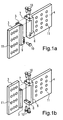
- a first connecting element 3 is provided, which can be inserted into a slot in a post 2, and a second connecting element 4, which in an end Recess of a bolt 1 can be mounted, so as shown in FIGS. 5a and 5b.
- the second connecting element 4 is a second anchoring element 6, which is also designed as a bearing plate is.
- the two anchoring elements 5 and 6 are each fixed (in one piece) connected to the connecting elements 3, 4.
- bearing blocks 7, 8 and / or 9 integrally formed to the assembly with the respective To allow anchoring element 5 or 6.
- FIG second anchoring element 6 an overhead bearing block 7 on which with two recesses for the implementation of bolts 10 is provided.
- the front upper side of the first anchoring element 5 of the first connecting element 3 is corresponding provided with two recesses into which the bolts 10 are insertable.
- a lower bracket 9 of the first serves for further fastening Anchoring element 5, which to facilitate the Assembly is provided with an elongated hole through which a Bolt 10 is feasible, which, as shown, in a Recess of the second connecting element 4 can be screwed in is.
- This construction corresponds to the representation of Fig. 6a and 6b and is particularly suitable for the cases in which the latch 1 is also accessible from its underside.
- the latch as shown in Figs. 7a and 7b, possibly is difficult to access from below, the 1b construction used. It is possible on a lower bracket 8 of the second connecting element 4 pre-assemble two bolts 10. The corresponding lower recesses or bores of the first anchoring element 5 are not visible in Fig. 1b. Can be used for assembly then the pre-assembled, protruding bolts 10 in the lower end recesses of the first anchoring element 5 be plugged in. The rest of the latch is then positioned and by means of the upper bolts 10 which pass through the upper Bearing block 7 are introduced, assembled.
- FIGS. 8 and 9 show a further embodiment of the Connection device according to the invention.
- a first Connecting element 3 in a vertical slot Post 2 mounted.
- a variety of attachments are used Recesses 11 through which screws or dowels can be inserted are.
- On the first connecting element 3 is a plate-shaped, from this protruding towards a bolt 1 first anchoring element 12 attached or in one piece formed with the first connecting element 3.
- a plurality of recesses 13 are provided in the first Anchoring element 12.
- a second connecting element 4 added which also for its attachment is provided with a plurality of recesses 11 through which dowels 14 or screws can be pushed through.
- This second anchoring element 15 comprises two mutually parallel plates 16, 17, which so are spaced from each other that there is a slot between forms them into which the first anchoring element 12 can be inserted is.
- the two plates 16, 17 each have several Recesses 18, 19, which with the recesses 13 of the first anchoring element 12 are aligned. So it is possible the fastening by means of screws 20, which are in the form of Allen screws can be trained to make.
- screws 20, which are in the form of Allen screws can be trained to make.
- the recess 19 can be provided with an internal thread, while the recess 18 is designed as a smooth bore. It goes without saying that counter nuts can also be provided, to hold the screw 20.
- first connecting element 3 on both sides can be provided with a first anchoring element 12 in order to to realize bars on both sides.
- the first Connecting element 3 would then be symmetrical to one Longitudinal plane or longitudinal axis of the post built up.
- An embodiment provides that the plates 16 and 17 up and down over the plate of the second connector 4 project.
- One of the nuts 22 can also be replaced by a head of the screw 21.
- the screw 21 (Threaded rod) can be easily through the in the post 1 inserted slot in which the first connecting element 3 is included. It results thus a very significant additional increase in Rigidity of the overall construction.
Landscapes
- Engineering & Computer Science (AREA)
- Architecture (AREA)
- Physics & Mathematics (AREA)
- Electromagnetism (AREA)
- Civil Engineering (AREA)
- Structural Engineering (AREA)
- Joining Of Building Structures In Genera (AREA)
Abstract
Description
- Fig. 1a
- eine perspektivische Ansicht eines ersten Ausführungsbeispiels zweier zueinander passender Verbindungselemente,
- Fig. 1b
- eine perspektivische Ausgestaltung eines zweiten Ausführungsbeispiels zweier zueinander passender Verbindungselemente,
- Fig. 2a
- eine perspektivische Ansicht eines Teilbereichs eines Riegels und eines Pfostens mit der in Fig. 1a gezeigten Konstruktion,
- Fig. 2b
- eine Ansicht analog Fig. 2a mit der in Fig. 1b gezeigten Konstruktion,
- Fig. 3a
- Ansichten des zweiten Verbindungselements gemäß der Ausgestaltung von Fig. 1a,
- Fig. 3b
- Ansichten analog Fig. 3a, gemäß dem Ausführungsbeispiel der Fig. 1b,
- Fig. 4a
- Ansichten des ersten Verbindungselements gemäß der Ausgestaltung zu Fig. 1a,
- Fig. 4b
- Ansichten des Verbindungselements analog Fig. 4a, jedoch in Darstellung des Ausführungsbeispiels der Fig. 1b,
- Fig. 5a
- eine stirnseitige Ansicht eines Riegels zur Aufnahme des zweiten Verbindungselements,
- Fig. 5b
- eine stirnseitige Ansicht des Riegels, analog Fig. 5a, mit eingesetztem Verbindungselement,
- Fig. 6a und 6b
- perspektivische Darstellungen der Montage und Verwendung des Ausführungsbeispiels der Fig. 1a,
- Fig. 7a und 7b
- Ansichten analog Fig. 6a und 6b des in Fig. 1b dargestellten Ausführungsbeispiels,
- Fig. 8
- eine perspektivische, stark vereinfachte Ansicht eines weiteren Ausführungsbeispiels der Erfindung, und
- Fig. 9
- eine Draufsicht auf die in Fig. 1 gezeigte Anordnung.
Claims (10)
- Verbindungseinrichtung für eine Holz-Pfosten-Riegel-Verbindung zum stirnseitigen Anschluss zumindest eines Riegels (1) an einen Pfosten (2), mit einem ersten, in einen Schlitz des Pfostens (2) einführbaren, plattenartigen Verbindungselement (3), welches an seinem äußeren Bereich zumindest ein erstes Verankerungselement (5) aufweist, mit welchem zumindest ein zweites Verankerungselement (6) eines zweiten, plattenartigen Verbindungselement (4) verbindbar ist, welches in eine stirnseitige Ausnehmung eines Riegels (1) einführbar ist.
- Verbindungseinrichtung nach Anspruch 1, dadurch gekennzeichnet, dass das erste (5) und/oder zweite (6) Verankerungselement jeweils zumindest eine Lagerplatte umfasst.
- Verbindungseinrichtung nach Anspruch 2, dadurch gekennzeichnet, dass die Lagerplatte sich senkrecht zur Mittelebene des jeweiligen Verbindungselements (3, 4) erstreckt.
- Verbindungseinrichtung nach einem der Ansprüche 1 bis 3, dadurch gekennzeichnet, dass an dem ersten (5) und/oder zweiten (6) Verankerungselement zumindest ein Lagerbock (7, 8, 9) angeordnet ist.
- Verbindungseinrichtung nach Anspruch 4, dadurch gekennzeichnet, dass der Lagerbock (7, 8, 9) mit dem jeweils anderen Verankerungselement (5, 6) verbindbar ist.
- Verbindungseinrichtung nach Anspruch 5, dadurch gekennzeichnet, dass zur Verbindung des ersten Verbindungselements (3) mit dem zweiten Verbindungselement (4) Bolzen (10) vorgesehen sind.
- Verbindungseinrichtung nach Anspruch 6, dadurch gekennzeichnet, dass die Bolzen (10) als Gewindebolzen ausgebildet sind.
- Verbindungseinrichtung nach Anspruch 7, dadurch gekennzeichnet, dass zur Stabilisierung jeweils mehrere Gewindebolzen vorgesehen sind.
- Verbindungseinrichtung nach einem der Ansprüche 1 bis 8, dadurch gekennzeichnet, dass freie Enden des ersten Verbindungselements (3) und des zweiten Verbindungselements (4) jeweils mit Ausnehmungen (11) versehen sind.
- Verbindungseinrichtung nach einem der Ansprüche 1 bis 9, dadurch gekennzeichnet, dass die Verbindungselemente (3, 4) als Blechplatten ausgestaltet sind.
Applications Claiming Priority (2)
| Application Number | Priority Date | Filing Date | Title |
|---|---|---|---|
| DE10149537A DE10149537B4 (de) | 2001-10-08 | 2001-10-08 | Verbindungseinrichtung für eine Holz-Pfosten-Riegel-Verbindung |
| DE10149537 | 2001-10-08 |
Publications (2)
| Publication Number | Publication Date |
|---|---|
| EP1300521A1 true EP1300521A1 (de) | 2003-04-09 |
| EP1300521B1 EP1300521B1 (de) | 2009-12-16 |
Family
ID=7701763
Family Applications (1)
| Application Number | Title | Priority Date | Filing Date |
|---|---|---|---|
| EP02017210A Expired - Lifetime EP1300521B1 (de) | 2001-10-08 | 2002-07-31 | Verbindungseinrichtung für eine Holz-Pfosten-Riegel-Verbindung |
Country Status (4)
| Country | Link |
|---|---|
| EP (1) | EP1300521B1 (de) |
| AT (1) | ATE452251T1 (de) |
| DE (2) | DE10149537B4 (de) |
| DK (1) | DK1300521T3 (de) |
Cited By (2)
| Publication number | Priority date | Publication date | Assignee | Title |
|---|---|---|---|---|
| EP1736606A1 (de) | 2005-06-23 | 2006-12-27 | Neue Holzbau AG Lungern | Biegesteife und steckbare Verbindung für Tragwerkelemente |
| US10422123B2 (en) * | 2016-11-07 | 2019-09-24 | Simpson Strong-Tie Company Inc. | Concealed joist tie with sloped center flange |
Families Citing this family (1)
| Publication number | Priority date | Publication date | Assignee | Title |
|---|---|---|---|---|
| DE10352992B4 (de) * | 2003-11-13 | 2008-11-13 | Bohrenkämper, Gustav | Holzverbinder |
Citations (3)
| Publication number | Priority date | Publication date | Assignee | Title |
|---|---|---|---|---|
| US4299509A (en) * | 1978-08-31 | 1981-11-10 | Streif Ohg | Beam connector |
| EP0130145A1 (de) * | 1983-05-24 | 1985-01-02 | BSB Holzkonstruktionen AG | Lösbare Verbindung für Holzbalken |
| DE20022076U1 (de) * | 2000-12-29 | 2001-03-01 | Heidemann Modular Space Systems Ltd., North Yorkshire | Verbindungssystem für Tragwerkelemente im Holzbau |
Family Cites Families (3)
| Publication number | Priority date | Publication date | Assignee | Title |
|---|---|---|---|---|
| DE3401303C2 (de) * | 1984-01-16 | 1986-01-16 | Jan Dipl.-Ing. 8000 München Forster | Verbindungsmittel für Holzbauteile |
| DE3641799A1 (de) * | 1986-12-06 | 1988-06-16 | Gustav Bohrenkaemper | Vorrichtung zum verbinden zweier holzbalken |
| DE20011793U1 (de) * | 2000-07-07 | 2000-09-28 | Bohrenkämper, Gustav, 32257 Bünde | Verbindungsbeschlag |
-
2001
- 2001-10-08 DE DE10149537A patent/DE10149537B4/de not_active Expired - Fee Related
-
2002
- 2002-07-31 DE DE50214091T patent/DE50214091D1/de not_active Expired - Lifetime
- 2002-07-31 EP EP02017210A patent/EP1300521B1/de not_active Expired - Lifetime
- 2002-07-31 AT AT02017210T patent/ATE452251T1/de active
- 2002-07-31 DK DK02017210.2T patent/DK1300521T3/da active
Patent Citations (3)
| Publication number | Priority date | Publication date | Assignee | Title |
|---|---|---|---|---|
| US4299509A (en) * | 1978-08-31 | 1981-11-10 | Streif Ohg | Beam connector |
| EP0130145A1 (de) * | 1983-05-24 | 1985-01-02 | BSB Holzkonstruktionen AG | Lösbare Verbindung für Holzbalken |
| DE20022076U1 (de) * | 2000-12-29 | 2001-03-01 | Heidemann Modular Space Systems Ltd., North Yorkshire | Verbindungssystem für Tragwerkelemente im Holzbau |
Cited By (2)
| Publication number | Priority date | Publication date | Assignee | Title |
|---|---|---|---|---|
| EP1736606A1 (de) | 2005-06-23 | 2006-12-27 | Neue Holzbau AG Lungern | Biegesteife und steckbare Verbindung für Tragwerkelemente |
| US10422123B2 (en) * | 2016-11-07 | 2019-09-24 | Simpson Strong-Tie Company Inc. | Concealed joist tie with sloped center flange |
Also Published As
| Publication number | Publication date |
|---|---|
| ATE452251T1 (de) | 2010-01-15 |
| EP1300521B1 (de) | 2009-12-16 |
| DE10149537B4 (de) | 2005-09-22 |
| DK1300521T3 (da) | 2010-04-19 |
| DE10149537A1 (de) | 2003-06-05 |
| DE50214091D1 (de) | 2010-01-28 |
Similar Documents
| Publication | Publication Date | Title |
|---|---|---|
| DE2618442C2 (de) | Stütze für ein Geländer oder dergleichen | |
| DE2525791B2 (de) | Anordnung zum verbinden zweier aufeinander stossender platten- oder stangenfoermiger elemente | |
| DE1003937B (de) | Gelaenderkonstruktion, insbesondere fuer Treppen | |
| EP0136431A2 (de) | Konstruktion aus Profilstäben | |
| EP0478877A1 (de) | Vorrichtung zum lösbaren Verbinden zweier Profilstäbe | |
| DE2838163A1 (de) | Zerlegbares rahmensystem | |
| EP0976891B1 (de) | Aufbausystem | |
| DE4447208C2 (de) | Hakenträgersystem | |
| DE69221056T2 (de) | Zusammensetzungsmethode zur konstruktion modularer möbelstücke und so erhaltene möbelstücke | |
| EP1300521A1 (de) | Verbindungseinrichtung für eine Holz-Pfosten-Riegel-Verbindung | |
| EP0038086A2 (de) | Bausatz zur Herstellung von Gestellen, Möbeln, Regalen, transportablen Bauwerken und aus diesem Bausatz hergestellter Gegenstand | |
| DE3839369A1 (de) | Verbindungselement und verfahren zum verbinden von voll- oder leimholzbalken in gleicher ebene | |
| EP4114150A1 (de) | Erweiterungsbausatz | |
| DE10140878B4 (de) | Verbindungseinrichtung für eine Holz-Pfosten-Riegel-Verbindung | |
| EP1251478A2 (de) | Strebeneinrichtung | |
| DE29603402U1 (de) | Rahmenwerk mit Winkel- oder Eckverbindungen von Metallprofilen, insbesondere aus Leichtmetall | |
| DE60000313T2 (de) | Befestigungssystem an einer Säule für ein Trägerelement | |
| DE19604665A1 (de) | Querverbinder für Profilstäbe | |
| EP1491696A2 (de) | Profilverbindungssystem | |
| DE102024108108A1 (de) | Befestigungseinrichtung und Anordnung | |
| EP0952267B1 (de) | Element zum Verbinden von flächigen Schutzzaunelementen | |
| DE3721869A1 (de) | Verbindungseinrichtung | |
| DE2410211A1 (de) | Kombinationsmoebel | |
| DE102010019385B4 (de) | Steckfußhalter für eine Podest-, Bühnen- und Tribünenkonstruktion sowie eine derartige Konstruktion | |
| EP1744066B1 (de) | Fachwerk sowie Stäbe für ein Fachwerk |
Legal Events
| Date | Code | Title | Description |
|---|---|---|---|
| PUAI | Public reference made under article 153(3) epc to a published international application that has entered the european phase |
Free format text: ORIGINAL CODE: 0009012 |
|
| AK | Designated contracting states |
Kind code of ref document: A1 Designated state(s): AT BE BG CH CY CZ DE DK EE ES FI FR GB GR IE IT LI LU MC NL PT SE SK TR |
|
| AX | Request for extension of the european patent |
Extension state: AL LT LV MK RO SI |
|
| 17P | Request for examination filed |
Effective date: 20030729 |
|
| AKX | Designation fees paid |
Designated state(s): AT BE BG CH CY CZ DE DK EE ES FI FR GB GR IE IT LI LU MC NL PT SE SK TR |
|
| RAP1 | Party data changed (applicant data changed or rights of an application transferred) |
Owner name: HEIDEMANN, MAREN |
|
| 17Q | First examination report despatched |
Effective date: 20061204 |
|
| GRAP | Despatch of communication of intention to grant a patent |
Free format text: ORIGINAL CODE: EPIDOSNIGR1 |
|
| GRAS | Grant fee paid |
Free format text: ORIGINAL CODE: EPIDOSNIGR3 |
|
| GRAA | (expected) grant |
Free format text: ORIGINAL CODE: 0009210 |
|
| AK | Designated contracting states |
Kind code of ref document: B1 Designated state(s): AT BE BG CH CY CZ DE DK EE ES FI FR GB GR IE IT LI LU MC NL PT SE SK TR |
|
| REG | Reference to a national code |
Ref country code: GB Ref legal event code: FG4D Free format text: NOT ENGLISH |
|
| REG | Reference to a national code |
Ref country code: CH Ref legal event code: EP |
|
| REG | Reference to a national code |
Ref country code: IE Ref legal event code: FG4D |
|
| REG | Reference to a national code |
Ref country code: SE Ref legal event code: TRGR |
|
| REF | Corresponds to: |
Ref document number: 50214091 Country of ref document: DE Date of ref document: 20100128 Kind code of ref document: P |
|
| REG | Reference to a national code |
Ref country code: CH Ref legal event code: NV Representative=s name: KELLER & PARTNER PATENTANWAELTE AG WINTERTHUR |
|
| REG | Reference to a national code |
Ref country code: DK Ref legal event code: T3 |
|
| REG | Reference to a national code |
Ref country code: NL Ref legal event code: VDEP Effective date: 20091216 |
|
| PG25 | Lapsed in a contracting state [announced via postgrant information from national office to epo] |
Ref country code: FI Free format text: LAPSE BECAUSE OF FAILURE TO SUBMIT A TRANSLATION OF THE DESCRIPTION OR TO PAY THE FEE WITHIN THE PRESCRIBED TIME-LIMIT Effective date: 20091216 |
|
| REG | Reference to a national code |
Ref country code: IE Ref legal event code: FD4D |
|
| PG25 | Lapsed in a contracting state [announced via postgrant information from national office to epo] |
Ref country code: NL Free format text: LAPSE BECAUSE OF FAILURE TO SUBMIT A TRANSLATION OF THE DESCRIPTION OR TO PAY THE FEE WITHIN THE PRESCRIBED TIME-LIMIT Effective date: 20091216 Ref country code: EE Free format text: LAPSE BECAUSE OF FAILURE TO SUBMIT A TRANSLATION OF THE DESCRIPTION OR TO PAY THE FEE WITHIN THE PRESCRIBED TIME-LIMIT Effective date: 20091216 Ref country code: BG Free format text: LAPSE BECAUSE OF FAILURE TO SUBMIT A TRANSLATION OF THE DESCRIPTION OR TO PAY THE FEE WITHIN THE PRESCRIBED TIME-LIMIT Effective date: 20100316 Ref country code: ES Free format text: LAPSE BECAUSE OF FAILURE TO SUBMIT A TRANSLATION OF THE DESCRIPTION OR TO PAY THE FEE WITHIN THE PRESCRIBED TIME-LIMIT Effective date: 20100327 Ref country code: IE Free format text: LAPSE BECAUSE OF FAILURE TO SUBMIT A TRANSLATION OF THE DESCRIPTION OR TO PAY THE FEE WITHIN THE PRESCRIBED TIME-LIMIT Effective date: 20091216 Ref country code: PT Free format text: LAPSE BECAUSE OF FAILURE TO SUBMIT A TRANSLATION OF THE DESCRIPTION OR TO PAY THE FEE WITHIN THE PRESCRIBED TIME-LIMIT Effective date: 20100416 |
|
| PG25 | Lapsed in a contracting state [announced via postgrant information from national office to epo] |
Ref country code: CZ Free format text: LAPSE BECAUSE OF FAILURE TO SUBMIT A TRANSLATION OF THE DESCRIPTION OR TO PAY THE FEE WITHIN THE PRESCRIBED TIME-LIMIT Effective date: 20091216 Ref country code: SK Free format text: LAPSE BECAUSE OF FAILURE TO SUBMIT A TRANSLATION OF THE DESCRIPTION OR TO PAY THE FEE WITHIN THE PRESCRIBED TIME-LIMIT Effective date: 20091216 |
|
| PLBE | No opposition filed within time limit |
Free format text: ORIGINAL CODE: 0009261 |
|
| STAA | Information on the status of an ep patent application or granted ep patent |
Free format text: STATUS: NO OPPOSITION FILED WITHIN TIME LIMIT |
|
| PG25 | Lapsed in a contracting state [announced via postgrant information from national office to epo] |
Ref country code: CY Free format text: LAPSE BECAUSE OF FAILURE TO SUBMIT A TRANSLATION OF THE DESCRIPTION OR TO PAY THE FEE WITHIN THE PRESCRIBED TIME-LIMIT Effective date: 20091216 Ref country code: GR Free format text: LAPSE BECAUSE OF FAILURE TO SUBMIT A TRANSLATION OF THE DESCRIPTION OR TO PAY THE FEE WITHIN THE PRESCRIBED TIME-LIMIT Effective date: 20100317 |
|
| 26N | No opposition filed |
Effective date: 20100917 |
|
| BERE | Be: lapsed |
Owner name: HEIDEMANN, MAREN Effective date: 20100731 |
|
| PG25 | Lapsed in a contracting state [announced via postgrant information from national office to epo] |
Ref country code: MC Free format text: LAPSE BECAUSE OF NON-PAYMENT OF DUE FEES Effective date: 20100731 |
|
| PG25 | Lapsed in a contracting state [announced via postgrant information from national office to epo] |
Ref country code: IT Free format text: LAPSE BECAUSE OF FAILURE TO SUBMIT A TRANSLATION OF THE DESCRIPTION OR TO PAY THE FEE WITHIN THE PRESCRIBED TIME-LIMIT Effective date: 20091216 |
|
| REG | Reference to a national code |
Ref country code: FR Ref legal event code: ST Effective date: 20110331 |
|
| PG25 | Lapsed in a contracting state [announced via postgrant information from national office to epo] |
Ref country code: FR Free format text: LAPSE BECAUSE OF NON-PAYMENT OF DUE FEES Effective date: 20100802 |
|
| PG25 | Lapsed in a contracting state [announced via postgrant information from national office to epo] |
Ref country code: BE Free format text: LAPSE BECAUSE OF NON-PAYMENT OF DUE FEES Effective date: 20100731 |
|
| PG25 | Lapsed in a contracting state [announced via postgrant information from national office to epo] |
Ref country code: LU Free format text: LAPSE BECAUSE OF NON-PAYMENT OF DUE FEES Effective date: 20100731 |
|
| PG25 | Lapsed in a contracting state [announced via postgrant information from national office to epo] |
Ref country code: TR Free format text: LAPSE BECAUSE OF FAILURE TO SUBMIT A TRANSLATION OF THE DESCRIPTION OR TO PAY THE FEE WITHIN THE PRESCRIBED TIME-LIMIT Effective date: 20091216 |
|
| REG | Reference to a national code |
Ref country code: CH Ref legal event code: PCAR Free format text: NEW ADDRESS: EIGERSTRASSE 2 POSTFACH, 3000 BERN 14 (CH) |
|
| PGFP | Annual fee paid to national office [announced via postgrant information from national office to epo] |
Ref country code: GB Payment date: 20170724 Year of fee payment: 16 Ref country code: DE Payment date: 20170731 Year of fee payment: 16 Ref country code: CH Payment date: 20170724 Year of fee payment: 16 |
|
| PGFP | Annual fee paid to national office [announced via postgrant information from national office to epo] |
Ref country code: AT Payment date: 20170719 Year of fee payment: 16 Ref country code: SE Payment date: 20170724 Year of fee payment: 16 Ref country code: DK Payment date: 20170724 Year of fee payment: 16 |
|
| REG | Reference to a national code |
Ref country code: DE Ref legal event code: R119 Ref document number: 50214091 Country of ref document: DE |
|
| REG | Reference to a national code |
Ref country code: DK Ref legal event code: EBP Effective date: 20180731 |
|
| REG | Reference to a national code |
Ref country code: CH Ref legal event code: PL |
|
| REG | Reference to a national code |
Ref country code: AT Ref legal event code: MM01 Ref document number: 452251 Country of ref document: AT Kind code of ref document: T Effective date: 20180731 |
|
| GBPC | Gb: european patent ceased through non-payment of renewal fee |
Effective date: 20180731 |
|
| REG | Reference to a national code |
Ref country code: SE Ref legal event code: EUG |
|
| PG25 | Lapsed in a contracting state [announced via postgrant information from national office to epo] |
Ref country code: LI Free format text: LAPSE BECAUSE OF NON-PAYMENT OF DUE FEES Effective date: 20180731 Ref country code: CH Free format text: LAPSE BECAUSE OF NON-PAYMENT OF DUE FEES Effective date: 20180731 Ref country code: DE Free format text: LAPSE BECAUSE OF NON-PAYMENT OF DUE FEES Effective date: 20190201 Ref country code: GB Free format text: LAPSE BECAUSE OF NON-PAYMENT OF DUE FEES Effective date: 20180731 Ref country code: AT Free format text: LAPSE BECAUSE OF NON-PAYMENT OF DUE FEES Effective date: 20180731 |
|
| PG25 | Lapsed in a contracting state [announced via postgrant information from national office to epo] |
Ref country code: SE Free format text: LAPSE BECAUSE OF NON-PAYMENT OF DUE FEES Effective date: 20180801 |
|
| PG25 | Lapsed in a contracting state [announced via postgrant information from national office to epo] |
Ref country code: DK Free format text: LAPSE BECAUSE OF NON-PAYMENT OF DUE FEES Effective date: 20180731 |