EP1300527A2 - Device for fixing listel rails, especially listel rails designed as skirting boards - Google Patents
Device for fixing listel rails, especially listel rails designed as skirting boards Download PDFInfo
- Publication number
- EP1300527A2 EP1300527A2 EP02022193A EP02022193A EP1300527A2 EP 1300527 A2 EP1300527 A2 EP 1300527A2 EP 02022193 A EP02022193 A EP 02022193A EP 02022193 A EP02022193 A EP 02022193A EP 1300527 A2 EP1300527 A2 EP 1300527A2
- Authority
- EP
- European Patent Office
- Prior art keywords
- rail
- strip
- profile
- area
- intermediate rail
- Prior art date
- Legal status (The legal status is an assumption and is not a legal conclusion. Google has not performed a legal analysis and makes no representation as to the accuracy of the status listed.)
- Withdrawn
Links
- 238000003780 insertion Methods 0.000 claims abstract description 24
- 230000037431 insertion Effects 0.000 claims abstract description 24
- 230000007704 transition Effects 0.000 claims description 24
- 239000002023 wood Substances 0.000 claims description 5
- 229910052751 metal Inorganic materials 0.000 claims description 4
- 239000002184 metal Substances 0.000 claims description 4
- 238000006073 displacement reaction Methods 0.000 claims description 3
- 239000000835 fiber Substances 0.000 claims description 3
- 239000007787 solid Substances 0.000 claims description 3
- 229910052782 aluminium Inorganic materials 0.000 claims description 2
- XAGFODPZIPBFFR-UHFFFAOYSA-N aluminium Chemical compound [Al] XAGFODPZIPBFFR-UHFFFAOYSA-N 0.000 claims description 2
- 239000007799 cork Substances 0.000 claims description 2
- 238000005192 partition Methods 0.000 claims description 2
- 239000000463 material Substances 0.000 description 8
- 210000004013 groin Anatomy 0.000 description 7
- 238000010276 construction Methods 0.000 description 6
- 238000009408 flooring Methods 0.000 description 6
- 238000009434 installation Methods 0.000 description 4
- 238000004519 manufacturing process Methods 0.000 description 4
- 238000011161 development Methods 0.000 description 2
- 230000018109 developmental process Effects 0.000 description 2
- 238000000465 moulding Methods 0.000 description 2
- 230000036316 preload Effects 0.000 description 2
- 239000002689 soil Substances 0.000 description 2
- 230000006978 adaptation Effects 0.000 description 1
- 230000015572 biosynthetic process Effects 0.000 description 1
- 230000000903 blocking effect Effects 0.000 description 1
- 238000004140 cleaning Methods 0.000 description 1
- 239000011888 foil Substances 0.000 description 1
- 239000003292 glue Substances 0.000 description 1
- 230000010354 integration Effects 0.000 description 1
- 230000013011 mating Effects 0.000 description 1
- 239000007769 metal material Substances 0.000 description 1
- 239000011505 plaster Substances 0.000 description 1
- 230000000284 resting effect Effects 0.000 description 1
- 230000008719 thickening Effects 0.000 description 1
- 230000000007 visual effect Effects 0.000 description 1
Images


Classifications
-
- E—FIXED CONSTRUCTIONS
- E04—BUILDING
- E04F—FINISHING WORK ON BUILDINGS, e.g. STAIRS, FLOORS
- E04F19/00—Other details of constructional parts for finishing work on buildings
- E04F19/02—Borders; Finishing strips, e.g. beadings; Light coves
- E04F19/04—Borders; Finishing strips, e.g. beadings; Light coves for use between floor or ceiling and wall, e.g. skirtings
- E04F19/0459—Borders; Finishing strips, e.g. beadings; Light coves for use between floor or ceiling and wall, e.g. skirtings characterised by the fixing method
- E04F19/0468—Plinths fixed by hooking in a direction parallel to the wall
-
- E—FIXED CONSTRUCTIONS
- E04—BUILDING
- E04F—FINISHING WORK ON BUILDINGS, e.g. STAIRS, FLOORS
- E04F19/00—Other details of constructional parts for finishing work on buildings
- E04F19/02—Borders; Finishing strips, e.g. beadings; Light coves
- E04F19/04—Borders; Finishing strips, e.g. beadings; Light coves for use between floor or ceiling and wall, e.g. skirtings
- E04F19/0495—Plinths fixed around wall openings or around corners of walls
-
- E—FIXED CONSTRUCTIONS
- E04—BUILDING
- E04F—FINISHING WORK ON BUILDINGS, e.g. STAIRS, FLOORS
- E04F19/00—Other details of constructional parts for finishing work on buildings
- E04F19/02—Borders; Finishing strips, e.g. beadings; Light coves
- E04F19/04—Borders; Finishing strips, e.g. beadings; Light coves for use between floor or ceiling and wall, e.g. skirtings
- E04F2019/0404—Borders; Finishing strips, e.g. beadings; Light coves for use between floor or ceiling and wall, e.g. skirtings characterised by the material
- E04F2019/0409—Borders; Finishing strips, e.g. beadings; Light coves for use between floor or ceiling and wall, e.g. skirtings characterised by the material of wood
-
- E—FIXED CONSTRUCTIONS
- E04—BUILDING
- E04F—FINISHING WORK ON BUILDINGS, e.g. STAIRS, FLOORS
- E04F19/00—Other details of constructional parts for finishing work on buildings
- E04F19/02—Borders; Finishing strips, e.g. beadings; Light coves
- E04F19/04—Borders; Finishing strips, e.g. beadings; Light coves for use between floor or ceiling and wall, e.g. skirtings
- E04F2019/044—Borders; Finishing strips, e.g. beadings; Light coves for use between floor or ceiling and wall, e.g. skirtings with conduits
-
- E—FIXED CONSTRUCTIONS
- E04—BUILDING
- E04F—FINISHING WORK ON BUILDINGS, e.g. STAIRS, FLOORS
- E04F19/00—Other details of constructional parts for finishing work on buildings
- E04F19/02—Borders; Finishing strips, e.g. beadings; Light coves
- E04F19/04—Borders; Finishing strips, e.g. beadings; Light coves for use between floor or ceiling and wall, e.g. skirtings
- E04F2019/0454—Borders; Finishing strips, e.g. beadings; Light coves for use between floor or ceiling and wall, e.g. skirtings with decorative effects
Definitions
- the invention relates to a device for fastening strip rails, especially of skirting boards designed as skirting boards, according to Preamble of claim 1.
- Such devices for fastening strip rails are for covering or bridging joints is generally known. This is how they become Devices e.g. B. used when between a side wall area and an unsightly floor wall area provided with a floor covering Joint covered between the floor covering and the side wall area shall be.
- Such a device for fastening slat rails is known for example from DE 211 03 12, in which an L-shaped Mounting rail is attached to a side wall surface by means of nails, a lower L-leg flush with an adjacent one Screed is inserted in a screed joint. On a front of this mounting rail two mounting profiles are arranged, in the corresponding counter profiles can be locked onto the last rail.
- the mounting rail is partly plastered with, so that the skirting board designed as a skirting board with an upper end region seen in cross section via an elastic Lips against the wall plaster.
- a floor covering is applied to the screed, to the side wall with a gap as a joint to the Mounting rail adjoins.
- the ledge rail points to cover this joint an elastic end section seen in cross section Lip on the floor covering.
- This is the structure is therefore a cleaning and screed gauge, which also serves as a mounting rail for is designed as skirting boards.
- Such Ledge rail is generally not suitable for conventional applications of Ledge rails that are retrofitted.
- a device for fastening as Skirting rails in which a mounting rail seen in cross section is L-shaped, the one Vertical L-legs assigned to the wall area as double legs two parallel walls are formed, approximately in a central area form a locking profile.
- This locking profile is a counter-locking profile on one wall protruding from an inner wall region of the skirting.
- the skirting board is used to lock the skirting board to the mounting rail from above with the wall having the counter profile down pressed between the double leg arrangement.
- the locking profiles and counter-locking profiles are formed here by material thickening.
- EP 0 900 897 A2 is a fastening device of skirting boards, in particular of skirting boards Ledge rails, known, the one mounting rail, an intermediate rail and has a last rail.
- the mounting rail and the strip rail can each be connected to the intermediate rail by means of a plug connection.
- the plug connection between the mounting rail and the intermediate rail is due to a first intermediate rail profile on the intermediate rail side and an associated mounting rail-side mounting rail counter profile educated.
- the detachable plug connection between the strip rail and the intermediate rail is, however, by an intermediate rail side second intermediate rail profile and an associated rail rail side Ledge rail counter profile formed.
- the mounting rail with an edge area of a floor covering is specific here assigned receiving space in which this flooring edge area is positively embraced.
- the mounting rail points to this in this area has an approximately U-shaped cross section.
- the U-leg resting on top of the flooring is a double leg formed between which the intermediate rail profile as a locking profile is trained.
- the intermediate rail is L-shaped, wherein on an approximately horizontal L-leg when assembled the intermediate rail, the first intermediate rail profile also as a locking profile is trained. For locking this first intermediate rail locking profile with the associated mounting rail counter-locking profile the intermediate rail from the front, d. H. with parallel to the top of the flooring running direction between the double legs of the upper U-leg inserted and locked into the mounting rail.
- the second intermediate rail profile is designed as a locking profile, which a ledge rail counter profile as a counter-locking profile on a lower one Inner wall area of the ledge rail is assigned.
- This ledge rail counter-locking profile is in an approximately U-shaped groove-shaped seen in cross section Recording room on the lower inner wall area of the strip rail educated.
- To lock the last rail with the intermediate rail the last rail approximately parallel to the one running at right angles to the floor covering Sidewall area, d. H. with a roughly transverse to the first plug and Sliding direction of the horizontal L-leg of the intermediate rail vertical plug and slide direction plugged onto the intermediate rail and locked there.
- Such a structure in which the mounting rail has a floor covering edge area accommodates in a receiving housing is on the one hand relatively complex in the manufacture and on the other hand to assemble relatively complex.
- On such a structure with a separate intermediate rail has the advantage that this enables a particularly stable and simple locking of the slat rail is possible in the coverage area, such a structure with an L-shaped intermediate rail overall, however, a relatively large amount of installation space Claim, so that additional functional parts, such as B. a cable duct, can only be integrated with difficulty.
- additional functional parts such as B. a cable duct
- such Structure in which a floor covering edge area in a receiving housing is encompassed, a fastening of the mounting rail on the wall and / or floor area can be avoided because the mounting rail through the flooring itself is fixed.
- a structure is particularly related with thin or softer floor coverings relatively unstable and shaky, so that therefore no high-quality covering for joints in the transition area from horizontal to vertical wall areas is possible.
- the object of the invention is therefore a device for fastening Molding rails, in particular molding strips designed as skirting boards, to create the integration of different functional parts while maintaining a compact design that allows for simple Is adaptable to different installation situations and the under Maintaining a stable structure can also be easily adapted to working floors is.
- the plug connection is designed such that the Strip rail and the mounting rail with the intermediate rail each with can be connected in approximately the same plug direction.
- the intermediate rail can advantageously be elongated, d. H. for example roughly rod-shaped, so that a narrower and therefore more compact structure of the strip rail that can be connected to it, preferably a baseboard, which is a total attractive, elegant overall visual impression of a strip rail arrangement results.
- this also allows other functional parts, such as z. B. a cable duct can be easily integrated into the device, since there is still corresponding installation space here without for this purpose, the groin rail as such is undesirably enlarged got to.
- the intermediate rail profiles based on the intermediate rail cross-section at least at intermediate rail end regions lying on opposite sides of the intermediate rail are formed, the intermediate rail end regions for connecting the strip rail and the mounting rail to the Intermediate rail with approximately the same insertion direction in an approximately opposite one Show direction.
- the mounting rail according to claim 3 is particularly preferably with a Outside of a mounting rail contact area running in the direction of insertion in a preferably flat system connection to an in approximately parallel to this also in the plug-in direction of the first contact area on, which is preferably formed by a wall area which approximately runs at right angles to a floor wall area.
- the groin rail covers in the state connected to the mounting rail via the intermediate rail the mounting rail and thus the intermediate rail completely, whereby the strip rail also has a first strip rail end region, seen in cross section at the first investment area and with a cross-section seen second strip rail end area at a second contact area is applied. This second investment area closes with the first investment area an angle, preferably a right angle.
- the second investment area is preferably a floor area, e.g. B. on a bottom wall area surface covering.
- a floor area e.g. B. on a bottom wall area surface covering.
- Such a structure is special easy to manufacture and also enables good and safe coverage and covering an unwanted joint area, e.g. B. in the transition area between a side wall area and one on a bottom wall area overlying floor covering in connection with skirting boards as Make tracks.
- the mounting rail on the first contact area be set, e.g. B. by means of screws and / or nails and / or glue, the profiles and counter profiles are designed so that the strip rail when the second contact area is lowered in the direction of insertion can be pressed to reinstall the second strip end area in the second investment area.
- This is particularly the case with subsidence soils advantageous, with the structure according to the invention, as already mentioned above has been explained in more detail, larger distances can also be bridged, z. B according to a specific embodiment up to 3 mm.
- the mounting rail approximately L-shaped, the mounting rail contact area is formed by a first L-leg.
- a second L-leg is in aligned approximately at right angles to the direction of insertion and thus to the first L-leg. This is a particularly good installation of the mounting rail z. B. in Sidewall area and in the adjacent floor area, e.g. B. on a floor covering, possible.
- the second L-leg is in the assembled Basic state for a stable construction with an outside in a preferably flat system connection on the parallel to the second L-leg approximately at right angles to the first investment area, the second Investment area.
- the second L-leg in the longitudinal direction of the mounting rail extending cable duct formed.
- This is preferably a cable duct formed according to claim 8 at an end portion of the second L-leg.
- the cable duct can have an approximately U-shaped cross section.
- Such a cable duct can thus be used for electrical lines or the like covered in a particularly simple manner, advantageously under the last rail to be arranged in such a way that they are not undesirable Way in the interior of a room are visible and above all accessible.
- easy accessibility is also achieved these cables or the like possible, especially if the snap connections also solved again and then again z. B. can be locked.
- the second L-leg in the assembled state in one System connection also on a correspondingly assigned inner wall area the groin rail.
- This inner wall area is according to claim 10 preferably designed so that the second L-leg during a shift the strip rail relative to the mounting rail, such as this. B. at one Pressing is the case, is in a system connection on the inner wall area and glides along. This makes it particularly stable and less shaky Overall construction of the device possible, even if a Press on a z. B. lowering floor is required.
- the strip rail in the assembled state with an inner wall area in a flat contact connection on an inside of the mounting rail contact area.
- the first is advantageous Ledge rail end area according to claim 12 at a distance above one End region of the mounting rail contact area arranged so that a Shifting the strip rail relative to the mounting rail is not blocked.
- Ledge rail end area according to claim 12 at a distance above one End region of the mounting rail contact area arranged so that a Shifting the strip rail relative to the mounting rail is not blocked.
- this stable structure will also then maintained when e.g. B. by lowering a floor area Reprinting is required.
- the profiles and counter profiles train.
- the mounting rail with at least one partial area in approximately mounting rail partition wall running parallel to the mounting rail contact area formed, at least on the cross section seen free upper end of the mounting rail intermediate wall, the mounting rail counter profile, preferably a mounting rail counter-locking profile, is trained.
- the mounting rail counter profile preferably a mounting rail counter-locking profile
- one is in the assembled state in the area inner wall area above the mounting rail intermediate wall the groin rail counter profile formed, preferably as a corresponding Counter locking profile is formed.
- the groin rail counter profile is according to claim 14 preferably as a groove-shaped and in the plug and slide direction aligned recess into which the second intermediate rail profile seen in the direction of insertion, preferably with the profiles locked, can be inserted and inserted.
- the profiles in the mated condition but also glued or by means of a shape and Clamping connection can be connected.
- second intermediate rail profile preferably by a cross section seen preferably tooth profile formed on opposite sides be formed to which a correspondingly suppressable tooth counter profile is assigned to the groin splint.
- the mounting rail counter profile is formed on an upper end wall end region as a tooth counter profile, which can be locked with the first intermediate rail profile designed as a tooth profile during a displacement in the plugging direction.
- the upper end wall end region is prestressed, preferably elastically prestressed, in the direction of the first intermediate rail profile.
- the upper end wall end region can here preferably be inclined towards the vertical by approximately 5 ° to 15 ° in the direction of the first intermediate rail profile.
- an insertion bevel is preferably formed at the end, to which the intermediate rail profile adjoins the opposite intermediate rail end, which preferably has an inclination suitably adapted to and towards the upper intermediate wall end region.
- the intermediate rail and the mounting rail are made possible, with a certain bias of the arrangement, ie in particular the baseboard in the direction of a z. B. side wall. Due to a certain inclination of the areas assigned to each other, a certain preload on a z. B. floor area.
- the preferably elastic preload ensures that a certain degree of flexibility in the manufacture of the z. B. latches for connecting the components together, which is particularly advantageous with regard to tolerance compensation due to manufacturing inaccuracies.
- the elastic prestress can be easily achieved, in particular, by producing the intermediate wall or the mounting rail from plastic. Basically, there are various options for designing the intermediate rail.
- the intermediate rail is formed according to a particularly preferred embodiment with an intermediate rail connecting web, from which the intermediate rail ends lying in the insertion direction and pointing in the opposite direction and having the intermediate rail profiles protrude on opposite sides.
- the intermediate rail can preferably be rod-shaped in cross section.
- the intermediate rail connecting web is particularly preferably designed as a transverse web which, in the assembled state, is oriented approximately transversely to the plug-in and slide direction.
- the intermediate rail ends are preferably arranged offset on one another on opposite sides of the intermediate rail connecting web, as viewed transversely to the plugging direction, the associated counter profiles being designed accordingly.
- the crossbar according to claim 22 is particularly preferably connected the second intermediate rail profile with the slat rail counter profile in a certain position on one also approximately transverse to the direction of insertion extending inner wall area of the strip rail. This can the structure as a whole is given even more stability.
- the profiles and counter-profiles extend in the longitudinal direction seen the last rail and the mounting rail at least over a sub-area.
- the extension of this is preferred Profiles along the entire longitudinal extent, as a result particularly advantageous and secure locking of the individual components together becomes possible.
- the slat rails can basically be used in a variety of ways, e.g. B. as wall connection strips, ceiling connection strips, transition strips or like.
- the use according to claim 24 is particularly preferred the skirting boards as skirting boards, because here in particular in connection with working floors and the given easy adjustment option, z. B. with a reprint, all the advantages of the invention Allow the structure to be used particularly well.
- the individual components can also be made of different materials or be made of the same materials.
- the strip rails have a core, preferably a core of medium-density fibers, which at least for Visible side with a covering, preferably a veneer and / or is covered with a decorative film.
- a wood veneer comes as veneer and / or a cork veneer in question, while the decorative film z. B. by a high-gloss and / or brushed aluminum foil can be formed.
- the skirting boards can also be made entirely of solid wood his.
- the use of plastic materials or the like is also possible.
- the intermediate rail and / or the mounting rail is preferred made of a plastic and / or a metal. Are here too however, other materials or material combinations are also possible.
- a particularly technically sophisticated decor strip arrangement results himself, if according to claim 27 the ledge rail on the visible side at least in some areas, preferably in the longitudinal direction of the rail extending recess, preferably a cutout, into which a Decorative strips can be used.
- a decorative strip can be individually and be chosen differently and z.
- the end caps and / or transition caps and / or inside corners and / or outside corners each have locking elements, which corresponding counter elements on the inner wall areas of the ledge rails assigned. This ensures that these elements are securely locked in place possible when assembled.
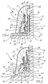
- FIG. 1 is an exploded view schematically and in perspective Representation of a device 1 for fastening baseboards 2 Strip rails shown, next to the baseboard 2, a mounting rail 3 and an intermediate rail 4 comprises.
- the mounting rail 3 and the baseboard 2 are each detachable Plug connection 5, 6 connectable to the intermediate rail 4, the Detachable connector 5 between the mounting rail 3 and the intermediate rail 4 by a first intermediate rail latching profile on the intermediate rail side 7 and an associated mounting rail counter-locking profile 8 is formed.
- the detachable connector 6 between the skirting 2 and the intermediate rail 4 is by means of a second intermediate rail locking profile on the intermediate rail side 9 and a skirting board mating profile assigned to it 10 formed.
- the mounting rail 3 is approximately L-shaped, with a first vertical L-leg 11 in the assembled state shown in FIG. 2 in one flat system connection on a side wall region running approximately parallel to it 12 is applied as a first investment area.
- a second horizontal one L-leg 13 runs approximately at right angles to the first vertical L-leg 11 and lies with an outside in a flat contact connection on a parallel to the second horizontal L-leg 13
- Flooring 14, e.g. B. a parquet floor as a second investment area. This floor covering 14 rests on a floor wall area 15, which is approximately is aligned perpendicular to the side wall region 12. Between the flooring 14 and the side wall region 12, a joint 16 is formed which be covered and covered with the device 1 according to the invention should.
- the Mounting rail 3 on the side wall area 12 z. B. by means of screws fixed, what in the vertical L-leg 11 of the mounting rail 3 corresponding Through bores 17 are arranged, of which in FIG. 1 only an example and drawn schematically on the mounting rail 3 is.
- a cable duct 18 is also formed, which has an approximately U-shaped cross section.
- the mounting rail counter-locking profile 8 as Tooth profile here is exemplified as a locking tooth.
- the top end 20 of the mounting rail intermediate wall 19, as can be seen in particular from FIG Fig. 2 can be seen, slightly inclined to the vertical, for. B. by about 5 ° to 10 °.
- the mounting rail counter-locking profile 8 is accordingly a tooth profile trained first intermediate rail locking profile on one of an intermediate rail crossbar 21 projecting intermediate rail end 22 assigned. At this intermediate rail end 22 there is an insertion bevel at the end 23, to which the first crossbar 21 crossbar Intermediate rail locking profile 7 connects.
- the intermediate rail crossbar 21 protrudes from the intermediate rail crossbar 21 a second in an opposite direction Intermediate rail end 24 away, the first intermediate rail end 22 and the second intermediate rail end 24 on opposite one another Sides of the intermediate rail crosspiece 21 offset from one another on opposite sides Crossbar end areas of the intermediate rail crossbar 21 are molded.
- the second intermediate rail locking profile 9 is on this second intermediate rail end 24 as seen in cross section on opposite Sides formed tooth profile. Alternatively but can also here the tooth profile only on one side of the intermediate rail end 24 be formed.
- such Structure of the device achieves that the intermediate rail locking profiles 7, 9 on opposite sides of the intermediate rail in relation to the cross section 4 with both lying in the same insertion direction 27 and in an opposite direction pointing intermediate rail ends 22, 24th the intermediate rail 4 are formed so that both the locking of the Skirting 2 with the intermediate rail 4 and the locking of the intermediate rail 4 with the mounting rail 3 each with the same direction of insertion 27 can be done.
- the order of connection of the individual components is Basically arbitrary, so z. B. in such a way that after assembly the mounting rail 3 first the connector 6 of the intermediate rail 4 with the skirting 2 and then the connector 5 of the intermediate rail 4 is produced with the mounting rail 3.
- the skirting board 2 covers with the Mounting rail 3 connected via the intermediate rail 4 state Mounting rail 3 and thus the intermediate rail 4 completely. Also lies seen in this assembled state, the baseboard 2 with a cross section first skirting board end region 28 on the side wall region 12 and with a second skirting board end region 29 seen in cross section on the floor covering 14 on. This allows the joint 16 to be covered very easily and easily.
- the second horizontal L-leg lies 13 in the assembled state of the device 1 in a system connection on a correspondingly assigned inner wall area 30 of the baseboard 2 and is supported on it.
- the skirting 2 is also in the assembled Condition with a further inner wall area 31 in a flat area Contact connection on an inside of the first vertical L-leg 11 and is based on it. This creates a very stable connection between the individual Components reached in the locked state of the device.
- the mounting rail counter-locking profile 8 only by means of the lead-in bevel 23 into a press-fit and ratchet-engaging engagement connection be brought with the first intermediate rail locking profile 7 can.
- the elastic bias can, for. B. be due to the fact that z. B. at least the upper end 20 of the mounting rail intermediate wall 19 a corresponding plastic material or the like is produced.
- the device 1 and here in particular the individual latching and counter-latching profiles 7 to 10 are designed such that if the bottom wall area 15 and thus the floor covering 14, the baseboard 2 in the direction of the arrow 32 can be easily replenished while maintaining the stable system in this transition area between the bottom wall area 15 and the Sidewall area 12, as has just been described in detail. Because, as can be seen from FIG. 3, such a pressing will the latching between the intermediate rail 4 and the mounting rail 3 set so that the tooth of the mounting rail counter-locking profile 8 based on the image plane of FIGS. 2 and 3 above with the first Intermediate rail locking profile is locked as compared to the Fig. 2 is the case.
- the intermediate rail crossbar 21 is still present an inner wall area of the baseboard 2.
- the inner wall areas 30, 31 designed so that this pressing and thus a Relative displacement of the skirting board 2 to the mounting rail 3 without blocking the pushing movement can be made in certain setting ranges can.
- the skirting board 2 was locked shown with the intermediate rail 4 so that the intermediate rail crossbar 21 in the locked state on the inner wall 25 in the region of the recess 26 is present. If necessary, could be used for an even larger bridging distance when pressing down there is also a distance between them Inner wall area and the intermediate rail crosspiece 21 can be used. In the adjacent state of the intermediate rail crossbar shown in FIGS. 2 and 3 21 on the inner wall 25 becomes a preferred stable one Structure of the catch created in connection with the baseboard 2.
- the skirting 2 can, for. B. be made of solid wood, but also a core from a z. B. have medium density fiber, at least for Visible side z. B. is covered with a decorative film or a veneer.
- the Intermediate rail 4 is preferably just like the mounting rail from one Made of plastic material. An alternative would be a metal material possible.
- Figures 4 to 6 is an outer corner 33 in different views (Figs. 4 and 5) as well as in a sectional view (Fig. 6), which, like this in particular 7, in an outer corner transition area (34) between two end faces and at a right angle to each other aligned base rails 2 is used, and with a edge overlap area 35 those adjacent in the adjoining area Skirting edge areas covered and overlapped.
- FIGS. 8 to 10 also show different views of an end cap 36 which, as can be seen in particular from FIG. 11, with an overlap area 37 on the edge Skirting end area covered and overlapped.
- FIGS. 12 to 16 show different views (FIGS. 12 to 15) as well a sectional view (Fig. 16) of an inner corner 38 is shown, which, as this in particular 17, in an inner corner transition area 39 between two adjoining end faces and approximately at right angles aligned skirting boards 2 is used.
- the inner corner 38 covers and overlaps the border areas adjacent to the adjacent area the baseboards 2 each with an overlap area 40.
- FIGS. 18 to 22 there is a transition cap 41 in various Views as well as shown in a sectional view (Fig. 22), the how This can be seen from FIG. 23 in a transition area 42 between two adjoining each other on the front and in the same longitudinal direction extending skirting 2 is used. Also covered and overlapped here the transition cap 41 those adjacent in the adjoining area Edge areas of the skirting boards 2 each with an edge overlap area 43rd
- the Outside corners 33, the end caps 36, the inside corners 38 and the transition caps 41 in each case wing-shaped locking elements on a wall area 44 which, depending on the embodiment, in different directions, d. H. can be directed forwards or backwards.
- This wing-like angularly projecting locking elements 44 is on the baseboards 2 in each case a corresponding counter element 46 is assigned, as can be seen in particular from Figures 1 to 3 can be seen.
- These counter elements 46 are exemplary here trained in the manner of a receiving groove. Form in the inserted state both the counter-elements 46 and the locking elements 44 are releasable Snap connection for a stable mounting of the outer corners 33, the end caps 36, the inner corners 38 and the transition caps 41 on each assigned skirting boards 2.
Landscapes
- Engineering & Computer Science (AREA)
- Architecture (AREA)
- Civil Engineering (AREA)
- Structural Engineering (AREA)
- Details Of Indoor Wiring (AREA)
- Pistons, Piston Rings, And Cylinders (AREA)
Abstract
Description
Die Erfindung betrifft eine Vorrichtung zur Befestigung von Leistenschienen,
insbesondere von als Sockelleisten ausgebildeten Leistenschienen, nach dem
Oberbegriff des Anspruchs 1.The invention relates to a device for fastening strip rails,
especially of skirting boards designed as skirting boards, according to
Preamble of
Derartige Vorrichtungen zur Befestigung von Leistenschienen sind zum Abdecken oder Überbrücken von Fugen allgemein bekannt. So werden derartige Vorrichtungen z. B. dann eingesetzt, wenn zwischen einem Seitenwandbereich und einem mit einem Bodenbelag versehenen Bodenwandbereich eine unansehnliche Fuge zwischen dem Bodenbelag und dem Seitenwandbereich abgedeckt werden soll. Eine derartige Vorrichtung zur Befestigung von Leistenschienen ist beispielsweise aus der DE 211 03 12 bekannt, bei der eine L-förmige Montageschiene mittels Nägeln an einer Seitenwandfläche befestigt wird, wobei ein unterer L-Schenkel oberflächenbündig mit einem angrenzenden Estrich in eine Estrichfuge eingesetzt ist. An einer Vorderseite dieser Montageschiene sind zwei Aufnahmeprofile angeordnet, in die entsprechende Gegenprofile an der Leistenschiene verrastet werden können. Die Montageschiene wird zum Teil mit verputzt, so dass die als Sockelleiste ausgebildete Leistenschiene mit einem im Querschnitt gesehen oberen Endbereich über eine elastische Lippe am Wandputz anliegt. Auf dem Estrich wird ein Bodenbelag aufgebracht, der zur Seitenwand hin mit einem Spaltabstand als Fuge an die Montageschiene angrenzt. Zur Abdeckung dieser Fuge weist die Leistenschiene an einem im Querschnitt gesehenen unteren Endbereich eine elastische Lippe auf, die am Bodenbelag aufliegt. Bei diesem Aufbau handelt es sich somit um eine Putz- und Estrichlehre, die zugleich als Montageschiene für als Sockelleisten ausgebildete Leistenschienen ausgebildet ist. Eine derartige Leistenschiene eignet sich regelmäßig nicht für herkömmliche Einsatzfälle von Leistenschienen, die nachträglich montiert werden.Such devices for fastening strip rails are for covering or bridging joints is generally known. This is how they become Devices e.g. B. used when between a side wall area and an unsightly floor wall area provided with a floor covering Joint covered between the floor covering and the side wall area shall be. Such a device for fastening slat rails is known for example from DE 211 03 12, in which an L-shaped Mounting rail is attached to a side wall surface by means of nails, a lower L-leg flush with an adjacent one Screed is inserted in a screed joint. On a front of this mounting rail two mounting profiles are arranged, in the corresponding counter profiles can be locked onto the last rail. The mounting rail is partly plastered with, so that the skirting board designed as a skirting board with an upper end region seen in cross section via an elastic Lips against the wall plaster. A floor covering is applied to the screed, to the side wall with a gap as a joint to the Mounting rail adjoins. The ledge rail points to cover this joint an elastic end section seen in cross section Lip on the floor covering. This is the structure is therefore a cleaning and screed gauge, which also serves as a mounting rail for is designed as skirting boards. Such Ledge rail is generally not suitable for conventional applications of Ledge rails that are retrofitted.
Weiter ist aus der GB-A-2 227 935 eine Vorrichtung zur Befestigung von als Sockelleisten ausgebildeten Leistenschienen bekannt, bei der eine Montageschiene im Querschnitt gesehen L-förmig ausgebildet ist, wobei der einem Wandbereich zugeordnete vertikale L-Schenkel als Doppelschenkel durch zwei parallel verlaufende Wände gebildet ist, die in etwa in einem mittleren Bereich ein Rastprofil ausbilden. Diesem Rastprofil ist ein Gegenrastprofil an einer von einem Innenwandbereich der Sockelleiste abstehenden Wand ausgebildet. Zum Verrasten der Sockelleiste mit der Montageschiene wird die Sockelleiste von oben mit der das Gegenprofil aufweisenden Wand nach unten zwischen die Doppelschenkelanordnung gedrückt. Die Rastprofile und Gegenrastprofile sind hier durch Materialverdickungen gebildet. Problematisch bei diesem Aufbau ist jedoch, dass hier eine stabile und wenig wacklige Verbindung zwischen der Sockelleiste und der Montageschiene nur bei ganz genau bestimmten Bodenverhältnissen gegeben ist. Bei einem nachträglichen Absenken des Bodens, was regelmäßig der Fall ist, kann es mit einem derartigen Aufbau dann leicht vorkommen, dass das Gegenrastprofil nicht mehr in einer Anlageverbindung am Rastprofil anliegt, wodurch es zu dem eben beschriebenen wackligen Aufbau der Anordnung kommen kann. Ein derartiger wackliger und weniger stabiler Aufbau ist unerwünscht und vermittelt zudem einen minderwertigen qualitativen Eindruck.Furthermore, from GB-A-2 227 935 a device for fastening as Skirting rails are known, in which a mounting rail seen in cross section is L-shaped, the one Vertical L-legs assigned to the wall area as double legs two parallel walls are formed, approximately in a central area form a locking profile. This locking profile is a counter-locking profile on one wall protruding from an inner wall region of the skirting. The skirting board is used to lock the skirting board to the mounting rail from above with the wall having the counter profile down pressed between the double leg arrangement. The locking profiles and counter-locking profiles are formed here by material thickening. Problematic with this structure, however, is that here a stable and less shaky connection between the skirting board and the mounting rail only if exactly certain soil conditions. In the event of a subsequent lowering of the floor, which is the case on a regular basis, it can with such a Then it can easily occur that the counter-locking profile is no longer in one System connection rests on the locking profile, making it to the one just described shaky structure of the arrangement can come. Such a shaky one and less stable construction is undesirable and also conveys an inferior one qualitative impression.
Aus der gattungsgemäßen EP 0 900 897 A2 ist eine Vorrichtung zur Befestigung von Leistenschienen, insbesondere von als Sockelleisten ausgebildeten Leistenschienen, bekannt, die eine Montageschiene, eine Zwischenschiene und eine Leistenschiene aufweist. Die Montageschiene und die Leistenschiene sind jeweils mittels einer Steckverbindung mit der Zwischenschiene verbindbar. Die Steckverbindung zwischen der Montageschiene und der Zwischenschiene ist durch ein zwischenschienenseitiges erstes Zwischenschienenprofil und ein diesem zugeordnetes montageschienenseitiges Montageschienen-Gegenprofil gebildet. Die lösbare Steckverbindung zwischen der Leistenschiene und der Zwischenschiene ist dagegen durch ein zwischenschienenseitiges zweites Zwischenschienenprofil und ein diesem zugeordnetes leistenschienenseitiges Leistenschienen-Gegenprofil gebildet.EP 0 900 897 A2 is a fastening device of skirting boards, in particular of skirting boards Ledge rails, known, the one mounting rail, an intermediate rail and has a last rail. The mounting rail and the strip rail can each be connected to the intermediate rail by means of a plug connection. The plug connection between the mounting rail and the intermediate rail is due to a first intermediate rail profile on the intermediate rail side and an associated mounting rail-side mounting rail counter profile educated. The detachable plug connection between the strip rail and the intermediate rail is, however, by an intermediate rail side second intermediate rail profile and an associated rail rail side Ledge rail counter profile formed.
Konkret ist hier die Montageschiene mit einem einem Bodenbelag-Randbereich zugeordneten Aufnahmeraum ausgebildet, in dem dieser Bodenbelag-Randbereich formschlüssig umgriffen aufgenommen ist. Dazu weist die Montageschiene in diesem Bereich einen in etwa U-förmigen Querschnitt auf. Der auf einer Bodenbelag-Oberseite aufliegende U-Schenkel ist als Doppelschenkel ausgebildet, zwischen denen das Zwischenschienenprofil als Rastprofil ausgebildet ist. Weiter ist hier die Zwischenschiene L-förmig ausgebildet, wobei an einem im montierten Zustand in etwa horizontal verlaufenden L-Schenkel der Zwischenschiene das erste Zwischenschienenprofil ebenfalls als Rastprofil ausgebildet ist. Zur Verrastung dieses ersten Zwischenschienen-Rastprofils mit dem diesem zugeordneten Montageschienen-Gegenrastprofil wird die Zwischenschiene von vorne her, d. h. mit parallel zur Bodenbelag-Oberseite verlaufender Steckrichtung zwischen die Doppelschenkel des oberen U-Schenkels der Montageschiene eingeschoben und verrastet. An dem in etwa vertikal von diesem horizontalen L-Schenkel abstehenden L-Schenkel der Zwischenschiene ist das zweite Zwischenschienenprofil als Rastprofil ausgebildet, dem ein Leistenschienen-Gegenprofil als Gegenrastprofil an einem unteren Innenwandbereich der Leistenschiene zugeordnet ist. Dieses Leistenschienen-Gegenrastprofil ist in einem im Querschnitt gesehen in etwa U-förmigen nutförmigen Aufnahmeraum am unteren Innenwandbereich der Leistenschiene ausgebildet. Zur Verrastung der Leistenschiene mit der Zwischenschiene wird die Leistenschiene in etwa parallel zum rechtwinklig zum Bodenbelag verlaufenden Seitenwandbereich, d. h. mit einer in etwa quer zur ersten Steck- und Schieberichtung des horizontalen L-Schenkels der Zwischenschiene verlaufender vertikaler Steck- und Schieberichtung auf die Zwischenschiene aufgesteckt und dort verrastet.The mounting rail with an edge area of a floor covering is specific here assigned receiving space in which this flooring edge area is positively embraced. The mounting rail points to this in this area has an approximately U-shaped cross section. The U-leg resting on top of the flooring is a double leg formed between which the intermediate rail profile as a locking profile is trained. Furthermore, the intermediate rail is L-shaped, wherein on an approximately horizontal L-leg when assembled the intermediate rail, the first intermediate rail profile also as a locking profile is trained. For locking this first intermediate rail locking profile with the associated mounting rail counter-locking profile the intermediate rail from the front, d. H. with parallel to the top of the flooring running direction between the double legs of the upper U-leg inserted and locked into the mounting rail. At about that L-leg of the intermediate rail projecting vertically from this horizontal L-leg the second intermediate rail profile is designed as a locking profile, which a ledge rail counter profile as a counter-locking profile on a lower one Inner wall area of the ledge rail is assigned. This ledge rail counter-locking profile is in an approximately U-shaped groove-shaped seen in cross section Recording room on the lower inner wall area of the strip rail educated. To lock the last rail with the intermediate rail the last rail approximately parallel to the one running at right angles to the floor covering Sidewall area, d. H. with a roughly transverse to the first plug and Sliding direction of the horizontal L-leg of the intermediate rail vertical plug and slide direction plugged onto the intermediate rail and locked there.
Ein solcher Aufbau, bei dem die Montageschiene einen Bodenbelag-Randbereich in einem Aufnahmegehäuse aufnimmt ist zum einen relativ aufwendig in der Herstellung und zum anderen auch relativ aufwendig zu montieren. Ein derartiger Aufbau mit einer separaten Zwischenschiene hat zwar den Vorteil, dass dadurch eine besonders stabile und einfache Verrastung der Leistenschiene im Abdeckungsbereich möglich wird, wobei ein derartiger Aufbau mit einer L-förmigen Zwischenschiene jedoch insgesamt relativ viel Bauraum in Anspruch nimmt, so dass in derartige Leistenanordnungen zusätzliche Funktionsteile, wie z. B. ein Kabelkanal, nur mit Mühe integriert werden können. Dies führt dann aber zwangsläufig zur Ausbildung von wuchtigen und wenig elegant wirkenden Leistenschienen. Insbesondere soll bei einem derartigen Aufbau, bei dem ein Bodenbelag-Randbereich in einem Aufnahmegehäuse umgriffen ist, eine Befestigung der Montageschiene am Wand- und/oder Bodenbereich vermieden werden, da die Montageschiene durch den Bodenbelag selbst fixiert wird. Ein derartiger Aufbau ist jedoch insbesondere in Verbindung mit dünnen oder weicheren Bodenbelägen relativ instabil und wacklig, so dass dadurch keine hochwertige Abdeckmöglichkeit für Fugen im Übergangsbereich von horizontalen zu vertikalen Wandbereichen möglich ist.Such a structure in which the mounting rail has a floor covering edge area accommodates in a receiving housing is on the one hand relatively complex in the manufacture and on the other hand to assemble relatively complex. On such a structure with a separate intermediate rail has the advantage that this enables a particularly stable and simple locking of the slat rail is possible in the coverage area, such a structure with an L-shaped intermediate rail overall, however, a relatively large amount of installation space Claim, so that additional functional parts, such as B. a cable duct, can only be integrated with difficulty. However, this inevitably leads to the formation of bulky and little elegant-looking skirting boards. In particular, such Structure in which a floor covering edge area in a receiving housing is encompassed, a fastening of the mounting rail on the wall and / or floor area can be avoided because the mounting rail through the flooring itself is fixed. However, such a structure is particularly related with thin or softer floor coverings relatively unstable and shaky, so that therefore no high-quality covering for joints in the transition area from horizontal to vertical wall areas is possible.
Aufgabe der Erfindung ist es daher, eine Vorrichtung zur Befestigung von Leistenschienen, insbesondere von als Sockelleisten ausgebildeten Leistenschienen, zu schaffen, die die Integration von unterschiedlichsten Funktionsteilen unter Beibehaltung eines kompakten Aufbaus ermöglicht, die auf einfache Weise an unterschiedliche Einbausituationen anpassbar ist und die unter Beibehaltung eines stabilen Aufbaus auch gut an arbeitende Böden anpassbar ist.The object of the invention is therefore a device for fastening Molding rails, in particular molding strips designed as skirting boards, to create the integration of different functional parts while maintaining a compact design that allows for simple Is adaptable to different installation situations and the under Maintaining a stable structure can also be easily adapted to working floors is.
Diese Aufgabe wird gelöst mit den Merkmalen des Anspruchs 1.This object is achieved with the features of
Gemäß Anspruch 1 ist die Steckverbindung jeweils so ausgebildet, dass die
Leistenschiene und die Montageschiene mit der Zwischenschiene jeweils mit
einer in etwa gleichen Steckrichtung verbindbar sind.According to
Ein derartiger Aufbau, bei dem sowohl die Verbindung zwischen der Leistenschiene und der Zwischenschiene als auch die Verbindung zwischen der Zwischenschiene und der Montageschiene mit einer gleichen Steckrichtung durchgeführt werden kann, ermöglicht eine besonders einfache und vorteilhafte Montage und ggf. auch Demontage.Such a structure, in which both the connection between the strip rail and the intermediate rail as well as the connection between the intermediate rail and the mounting rail with the same direction of insertion can be carried out, enables a particularly simple and advantageous Assembly and disassembly if necessary.
Zudem wird aufgrund dieser gleichen Steckrichtung auch eine besonders kompakte Vorrichtung insgesamt geschaffen. Denn durch die gleiche Steckrichtung kann die Zwischenschiene im Querschnitt gesehen vorteilhaft länglich, d. h. zum Beispiel in etwa stabförmig ausgebildet werden, so dass auch ein schmalerer und damit kompakter Aufbau der damit verbindbaren Leistenschiene, vorzugsweise einer Sockelleiste, möglich ist, was einen insgesamt ansprechenden eleganten optischen Gesamteindruck einer Leistenschienenanordnung ergibt. Zudem können dadurch auch weitere Funktionsteile, wie z. B. ein Kabelkanal noch auf einfache Weise in die Vorrichtung integriert werden, da hier dann noch entsprechender Bauraum vorhanden ist, ohne dass hierzu die Leistenschiene als solches in unerwünschter Weise vergrößert werden muss.In addition, this same direction of insertion also makes it special compact device created overall. Because by the same direction of insertion seen in cross section, the intermediate rail can advantageously be elongated, d. H. for example roughly rod-shaped, so that a narrower and therefore more compact structure of the strip rail that can be connected to it, preferably a baseboard, which is a total attractive, elegant overall visual impression of a strip rail arrangement results. In addition, this also allows other functional parts, such as z. B. a cable duct can be easily integrated into the device, since there is still corresponding installation space here without for this purpose, the groin rail as such is undesirably enlarged got to.
Ein weiterer besonderer Vorteil eines derartigen Aufbaus mit in etwa gleicher Steckrichtung bei der Verbindung, z. B. einer Verrastung, der Leistenschiene und der Montageschiene mit der Zwischenschiene ist, dass dadurch auch eine einfache und besonders gute Anpassungsmöglichkeit bei arbeitenden Böden möglich ist, z. B. ein Nachschieben bei einem sich absenkenden Boden, wobei hier zudem größere Abstände überbrückt werden können, da die jeweiligen Profile und Gegenprofile in der gleichen Steckrichtung liegen und daher z. B. die Länge in Steckrichtung gesehen hierzu vorteilhaft ausgenutzt werden kann.Another particular advantage of such a construction with approximately the same Plug direction in the connection, e.g. B. a latch, the groin rail and the mounting rail with the intermediate rail is also a simple and particularly good adjustment option for working floors is possible, e.g. B. a push on a subsiding floor, where larger distances can also be bridged here, since the respective Profiles and counter profiles are in the same direction and therefore z. B. the length seen in the direction of insertion can be used advantageously for this purpose.
Die weiteren mit diesem Aufbau verbundenen Vorteile werden aus den Unteransprüchen ersichtlich, die zweckmäßige und vorteilhafte Weiterbildungen der Erfindung beinhalten:The further advantages associated with this structure are set out in the subclaims evident, the expedient and advantageous developments of Invention include:
Gemäß einer konkreten Ausführungsform nach Anspruch 2 sind die Zwischenschienenprofile
bezogen auf den Zwischenschienen-Querschnitt wenigstens
an auf gegenüberliegenden Seiten der Zwischenschiene liegenden Zwischenschienen-Endbereichen
ausgebildet sind, wobei die Zwischenschienen-Endbereiche
zur Verbindung der Leistenschiene und der Montageschiene mit der
Zwischenschiene mit in etwa gleicher Steckrichtung in eine in etwa entgegengesetzte
Richtung weisen.According to a specific embodiment according to
Besonders bevorzugt liegt dabei die Montageschiene nach Anspruch 3 mit einer
Außenseite eines in Steckrichtung verlaufenden Montageschienen-Anlagebereichs
in einer vorzugsweise flächigen Anlageverbindung an einem in
etwa parallel dazu ebenfalls in Steckrichtung verlaufenden ersten Anlagebereich
an, der vorzugsweise durch einen Wandbereich gebildet ist, der in etwa
rechtwinklig zu einem Bodenwandbereich verläuft. Die Leistenschiene überdeckt
im mit der Montageschiene über die Zwischenschiene verbundenen Zustand
die Montageschiene und damit die Zwischenschiene vollständig, wobei
die Leistenschiene zudem mit einem im Querschnitt gesehen ersten Leistenschienen-Endbereich
am ersten Anlagebereich sowie mit einem im Querschnitt
gesehenen zweiten Leistenschienen-Endbereich an einem zweiten Anlagebereich
anliegt. Dieser zweite Anlagebereich schließt mit dem ersten Anlagebereich
einen Winkel, vorzugsweise einen rechten Winkel, ein. Der zweite Anlagebereich
ist dabei vorzugsweise ein Bodenbereich, z. B. ein auf einem Bodenwandbereich
aufliegender Bodenbelag. Ein derartiger Aufbau ist besonders
einfach herzustellen und ermöglicht zudem eine gute und sichere Überdeckung
und Abdeckung eines unerwünschten Fugenbereichs, z. B. im Übergangsbereich
zwischen einem Seitenwandbereich und einem auf einen Bodenwandbereich
aufliegenden Bodenbelag in Verbindung mit Sockelleisten als
Leistenschienen.The mounting rail according to
Gemäß Anspruch 4 kann dazu die Montageschiene am ersten Anlagebereich
festgelegt werden, z. B. mittels Schrauben und/oder Nägeln und/oder Kleber,
wobei die Profile und Gegenprofile so ausgebildet sind, dass die Leistenschiene
bei einem Absenken des zweiten Anlagebereichs in Steckrichtung
nachdrückbar ist zur Wiederanlage des zweiten Leistenschienen-Endbereichs
im zweiten Anlagebereich. Dies ist insbesondere bei sich absenkenden Böden
vorteilhaft, wobei mit dem erfindungsgemäßen Aufbau, wie dies oben bereits
näher erläutert worden ist, auch größere Abstände überbrückt werden können,
z. B gemäß einer konkreten Ausführungsform bis 3 mm. Ein derartiges Nachdrücken
wird somit auch bei festgelegter Montageschiene auf einfache Weise
möglich, die dann in einem derartigen Fall beabstandet oberhalb des Bodenbereichs
liegt, wobei jedoch die Leistenschiene mit ihren Endbereichen in einer
Anlageverbindung an den zugeordneten Anlagebereichen anliegt, wodurch
eine dauerhafte, gute und sichere Abdeckung des Fugenbereichs möglich ist.According to
Gemäß einer vorteilhaften Weiterbildung nach Anspruch 5 ist die Montageschiene
in etwa L-förmig ausgebildet, wobei der Montageschienen-Anlagebereich
durch einen ersten L-Schenkel gebildet ist. Ein zweiter L-Schenkel ist in
etwa rechtwinklig zur Steckrichtung und damit zum ersten L-Schenkel ausgerichtet.
Damit ist eine besonders gute Anlage der Montageschiene z. B. im
Seitenwandbereich und im angrenzenden Bodenbereich, z. B. auf einem Bodenbelag,
möglich. Gemäß Anspruch 6 liegt der zweite L-Schenkel im montierten
Grundzustand dabei für einen stabilen Aufbau mit einer Außenseite in
einer vorzugsweise flächigen Anlageverbindung an dem parallel zum zweiten
L-Schenkel in etwa rechtwinklig zum ersten Anlagebereich verlaufenden zweiten
Anlagebereich an.According to an advantageous development according to
Gemäß einer besonders bevorzugten Ausführungsform ist nach Anspruch 7
am zweiten L-Schenkel ein sich im Montageschienen-Längsrichtung
erstreckender Kabelkanal ausgebildet. Vorzugsweise ist dieser Kabelkanal
nach Anspruch 8 an einem Endbereich des zweiten L-Schenkels ausgebildet.
Der Kabelkanal kann einen in etwa U-förmigen Querschnitt aufweisen. Ein
derartiger Kabelkanal kann mit dem erfindungsgemäßen Aufbau somit auf
einfache Weise in die Vorrichtung integriert werden, ohne dass dies zu einer
unerwünscht großen und sperrigen Bauweise für die Leistenschiene führt. Mit
einem derartigen Kabelkanal können somit elektrische Leitungen oder dergleichen
auf besonders einfache Weise vorteilhaft abgedeckt unter der Leistenschiene
verlaufend angeordnet werden, so dass diese nicht in unerwünschter
Weise im Innenbereich eines Raumes sichtbar und vor allem zugänglich sind.
Mit dem erfindungsgemäßen Aufbau ist zudem eine einfache Zugänglichkeit zu
diesen Kabeln oder dergleichen möglich, insbesondere wenn die Rastverbindungen
auch wieder gelöst und danach wieder z. B. verrastet werden können.According to a particularly preferred embodiment, according to
Nach Anspruch 9 liegt der zweite L-Schenkel im montierten Zustand in einer
Anlageverbindung zudem an einem entsprechend zugeordneten Innenwandbereich
der Leistenschiene an. Dieser Innenwandbereich ist nach Anspruch 10
vorzugsweise so ausgebildet, dass der zweite L-Schenkel bei einer Verschiebung
der Leistenschiene relativ zur Montageschiene, wie dies z. B. bei einem
Nachdrücken der Fall ist, in einer Anlageverbindung am Innenwandbereich anliegt
und entlanggleitet. Damit wird ein besonders stabiler und wenig wackliger
Aufbau der Vorrichtung insgesamt möglich, und zwar auch dann, wenn ein
Nachdrücken bei einem sich z. B. absenkenden Boden erforderlich ist. According to
Nach Anspruch 11 kann auch die Leistenschiene im montierten Zustand mit
einem Innenwandbereich in einer flächigen Anlageverbindung an einer Innenseite
des Montageschienen-Anlagebereichs anliegen. Vorteilhaft ist der erste
Leistenschienen-Endbereich nach Anspruch 12 im Abstand oberhalb eines
Endbereichs des Montageschienen-Anlagebereichs angeordnet, so dass eine
Verschiebung der Leistenschiene relativ zur Montageschiene nicht blockiert ist.
Auch hier wird wiederum ein besonders stabiler und wenig wackliger Aufbau
der gesamten Vorrichtung erzielt. Dieser stabile Aufbau wird vor allem auch
dann beibehalten, wenn z. B. durch ein Absenken eines Bodenbereichs ein
Nachdrücken erforderlich wird.According to
Grundsätzlich gibt es verschiedene Möglichkeiten die Profile und Gegenprofile
auszubilden. Gemäß einer besonders bevorzugten Ausführungsform nach Anspruch
13 ist an der Montageschiene eine mit wenigstens einem Teilbereich in
etwa parallel zum Montageschienen-Anlagebereich verlaufende Montageschienen-Zwischenwand
ausgebildet, wobei wenigstens am im Querschnitt
gesehen freien oberen Ende der Montageschienen-Zwischenwand das Montageschienen-Gegenprofil,
vorzugsweise ein Montageschienen-Gegenrastprofil,
ausgebildet ist. Entsprechend ist an einem im montierten Zustand im Bereich
oberhalb der Montageschienen-Zwischenwand liegenden Innenwandbereich
das Leistenschienen-Gegenprofil ausgebildet, das vorzugsweise als entsprechendes
Gegenrastprofil ausgebildet ist. Das Leistenschienen-Gegenprofil ist
nach Anspruch 14 bevorzugt als nutförmige und in Steck- und Schieberichtung
ausgerichtete Ausnehmung ausgebildet, in die das zweite Zwischenschienenprofil
in Steckrichtung gesehen, vorzugsweise unter Verrastung der Profile,
einsteckbar und einschiebbar ist. Grundsätzlich können hier die Profile im
gesteckten Zustand aber auch verklebt werden oder mittels einem Form- und
Klemmschluss miteinander verbunden werden. Gemäß Anspruch 15 kann das
zweite Zwischenschienenprofil dabei vorzugsweise durch ein im Querschnitt
gesehen vorzugsweise auf gegenüberliegenden Seiten ausgebildetes Zahnprofil
gebildet sein, dem ein entsprechend überdrückbares Zahngegenprofil an
der Leistenschiene zugeordnet ist. Mit einer derartigen Ausbildung der einander
zugeordneten Profile und Gegenprofile zwischen Leistenschiene und Zwischenschiene
wird eine besonders einfache und sichere Verrastung zwischen
den beiden Bauteilen möglich, die zudem auch auf einfache Weise wieder
lösbar ist.There are basically different options for the profiles and counter profiles
train. According to a particularly preferred embodiment according to
Nach Anspruch 16 ist das Montageschienen-Gegenprofil an einem oberen
Zwischenwand-Endbereich als Zahngegenprofil ausgebildet, das mit dem als
Zahnprofil ausgebildeten ersten Zwischenschienenprofil bei einer Verschiebung
in Steckrichtung verrastbar ist. Vorzugsweise ist der obere Zwischenwand-Endbereich
hierbei nach Anspruch 17 in Richtung auf das erste Zwischenschienenprofil
hin vorgespannt, vorzugsweise elastisch vorgespannt.
Weiter kann der obere Zwischenwand-Endbereich nach Anspruch 18 hier vorzugsweise
um in etwa 5° bis 15° in Richtung zum ersten Zwischenschienenprofil
hin gegen die Vertikale geneigt sein. Am das erste Zwischenschienenprofil
aufweisenden Zwischenschienenende ist vorzugsweise endseitig eine
Einführschräge ausgebildet, an die sich zum entgegengesetzten Zwischenschienenende
hin das Zwischenschienenprofil anschließt, das vorzugsweise
eine Neigung entsprechend angepasst an und zu dem oberen Zwischenwand-Endbereich
hin aufweist. Mit einem derartigen Aufbau wird eine besonders sichere
und gute Verrastung zwischen der Zwischenschiene und der Montageschiene
ermöglicht, wobei hier zudem eine gewisse Vorspannung der Anordnung,
d. h. insbesondere der Sockelleiste in Richtung auf eine z. B. Seitenwand
hin erfolgt. Durch eine gewisse Neigung der einander zugeordneten Bereiche
kann hier zudem unter Beibehaltung der gleichen Steckrichtung auch
eine gewisse Vorspannung auf einen z. B. Bodenbereich hin erfolgen. Insbesondere
durch die vorzugsweise elastische Vorspannung wird dabei erreicht,
dass auch eine gewisse Nachgiebigkeit bei der Herstellung der z. B. Verrastungen
zur Verbindung der Bauteile miteinander gegeben ist, was insbesondere
im Hinblick auf einen Toleranzausgleich bedingt durch fertigungstechnische
Ungenauigkeiten von Vorteil ist. Die elastische Vorspannung lässt sich
dabei insbesondere durch die Herstellung der Zwischenwand bzw. der Montageschiene
aus Kunststoff leicht erreichen.
Grundsätzlich gibt es verschiedene Möglichkeiten die Zwischenschiene auszubilden.
Nach Anspruch 19 ist die Zwischenschiene gemäß einer besonders
bevorzugten Ausführungsform mit einem Zwischenschienen-Verbindungssteg
ausgebildet, von dem auf gegenüberliegenden Seiten die in der Steckrichtung
liegenden und in entgegengesetzte Richtung weisenden sowie die Zwischenschienenprofile
aufweisenden Zwischenschienenenden wegragen. Vorzugsweise
kann die Zwischenschiene hier im Querschnitt gesehen stabförmig ausgebildet
sein. Besonders bevorzugt ist jedoch nach Anspruch 20 der Zwischenschienen-Verbindungssteg
als Quersteg ausgebildet, der im montierten
Zustand in etwa quer zur Steck- und Schieberichtung ausgerichtet ist. Bevorzugt
liegen dann hier nach Anspruch 21 die Zwischenschienenenden auf gegenüberliegenden
Seiten des Zwischenschienen-Verbindungssteges quer zur
Steckrichtung gesehen versetzt zueinander angeordnet, wobei die zugeordneten
Gegenprofile entsprechend angepasst daran ausgebildet sind. Mit einem
derartigen versetzten Aufbau in Verbindung mit einem Quersteg kann eine besonders
einfache Anpassung an die baulichen Gegebenheiten erzielt werden,
insbesondere im Hinblick auf einen an der Montageschiene ausgebildeten Kabelkanal.
Ein derartiger Quersteg in Verbindung mit einer versetzten Anordnung
der Zwischenschienenenden ermöglicht somit unter Beibehaltung eines
kompakten Aufbaus der Zwischenschiene die erfindungsgemäße Verbindung
der einzelnen Bauteile mit in etwa gleicher Steckrichtung.According to
Basically, there are various options for designing the intermediate rail. According to
Besonders bevorzugt liegt der Quersteg nach Anspruch 22 bei einer Verbindung
des zweiten Zwischenschienenprofils mit dem Leistenschienen-Gegenprofil
in einer bestimmten Position an einem ebenfalls in etwa quer zur Steckrichtung
verlaufenden Innenwandbereich der Leistenschiene an. Dadurch kann
dem Aufbau insgesamt noch mehr Stabilität verliehen werden. The crossbar according to
Gemäß Anspruch 23 erstrecken sich die Profile und Gegenprofile in Längserstreckungsrichtung
der Leistenschiene und der Montageschiene gesehen
wenigstens über einen Teilbereich. Bevorzugt ist jedoch die Erstreckung dieser
Profile entlang des gesamten Längserstreckungsbereichs, da dadurch eine
besonders vorteilhafte und sichere Verrastung der einzelnen Bauteile miteinander
möglich wird.According to
Die Leistenschienen können grundsätzlich vielfältig eingesetzt werden, z. B.
als Wandanschlussleisten, Deckenanschlussleisten, Übergangsleisten oder
dergleichen. Besonders bevorzugt ist jedoch nach Anspruch 24 die Verwendung
der Leistenschienen als Sockelleisten, da sich hier insbesondere in Verbindung
mit arbeitenden Böden und der gegebenen einfachen Anpassungsmöglichkeit,
z. B. bei einem Nachdrücken, sämtliche Vorteile des erfindungsgemäßen
Aufbaus besonders gut ausnutzen lassen.The slat rails can basically be used in a variety of ways, e.g. B.
as wall connection strips, ceiling connection strips, transition strips or
like. However, the use according to
Die einzelnen Bauteile können grundsätzlich auch aus unterschiedlichen Materialien oder aus gleichen Materialien hergestellt sein. Besonders bevorzugt ist nach Anspruch 25 vorgesehen, dass die Leistenschienen einen Kern aufweisen, vorzugsweise einen Kern aus mitteldichten Fasern, der wenigstens zur Sichtseite hin mit einer Ummantelung, vorzugsweise einem Furnier und/oder einer Dekorfolie ummantelt ist. Als Furnier kommt beispielsweise ein Holzfurnier und/oder ein Korkfurnier in Frage, während die Dekorfolie z. B. durch eine hochglänzende und/oder gebürstete Aluminiumfolie gebildet sein kann. Alternativ dazu können die Leistenschienen aber auch ganz aus Massivholz hergestellt sein. Ebenso ist auch der Einsatz von Kunststoffmaterialien oder dergleichen möglich.In principle, the individual components can also be made of different materials or be made of the same materials. Is particularly preferred provided according to claim 25 that the strip rails have a core, preferably a core of medium-density fibers, which at least for Visible side with a covering, preferably a veneer and / or is covered with a decorative film. For example, a wood veneer comes as veneer and / or a cork veneer in question, while the decorative film z. B. by a high-gloss and / or brushed aluminum foil can be formed. alternative the skirting boards can also be made entirely of solid wood his. Likewise, the use of plastic materials or the like is also possible.
Nach Anspruch 26 ist die Zwischenschiene und/oder die Montageschiene bevorzugt
aus einem Kunststoff und/oder einem Metall hergestellt. Auch hier sind
jedoch auch andere Materialien bzw. Materialkombinationen möglich. According to
Eine designtechnisch besonders anspruchsvolle Dekorleistenanordnung ergibt sich, wenn gemäß Anspruch 27 die Leistenschiene auf der Sichtseite wenigstens bereichsweise eine sich vorzugsweise in Schienenlängsrichtung erstreckende Ausnehmung, vorzugsweise eine Ausfräsung, aufweist, in die ein Dekorstreifen einsetzbar ist. Ein derartiger Dekorstreifen kann individuell und unterschiedlich gewählt werden und sich z. B. an ein wiederkehrendes Innenraumelement anpassend gewählt werden.A particularly technically sophisticated decor strip arrangement results himself, if according to claim 27 the ledge rail on the visible side at least in some areas, preferably in the longitudinal direction of the rail extending recess, preferably a cutout, into which a Decorative strips can be used. Such a decorative strip can be individually and be chosen differently and z. B. a recurring interior element be chosen appropriately.
Mit den Ansprüchen 28 bis 31 werden Innenecken, Außenecken, Übergangskappen
und Abschlusskappen beansprucht, die an den jeweiligen Stellen z. B.
im Endbereich oder an den Übergangsstellen zwischen zwei Leistenschienen
eingesetzt werden und dort den oder die angrenzenden Leistenschienenbereiche
überlappen und überdecken. Dadurch können z. B. im Bereich von
Schnittstellen, z. B. bei Gehrungsschnitten oder Endstellen vorteilhafte optisch
ansprechende Abschluss- und Übergangselemente geschaffen werden, die
eine einheitliche Optik gewährleisten. Dadurch wird ein Leistensystem mit einem
besonders hochwertigen Eindruck herstellbar. Dies z. B. dadurch, dass
die einzelnen Elemente aus Metall und/oder einem Kunststoff hergestellt sind,
wie dies mit Anspruch 34 beansprucht wird.With
Nach Anspruch 32 und 33 weisen die Abschlusskappen und/oder Übergangskappen
und/oder Innenecken und/oder Außenecken jeweils Rastelemente auf,
denen entsprechende Gegenelemente an den Innenwandbereichen der Leistenschienen
zugeordnet sind. Dadurch ist eine sichere Verrastung dieser Elemente
im montierten Zustand möglich.According to
Die Erfindung wird nachfolgend anhand einer Zeichnung näher erläutert.The invention is explained in more detail with reference to a drawing.
Es zeigen:
- Fig. 1
- eine schematische, perspektivische Teilansicht einer erfindungsgemäßen Vorrichtung zur Befestigung von Leistenschienen mit einer Sockelleiste, einer Zwischenschiene und einer Montageschiene,
- Fig. 2
- die Vorrichtung gemäß Fig. 1 im zusammengebauten und montierten Zustand bei nicht abgesenktem Boden,
- Fig. 3
- die Vorrichtung gemäß Fig. 2 im nachgedrückten Zustand,
- Fig. 4
- eine schematische Unteransicht einer Außenecke,
- Fig. 5
- eine schematische Seitenansicht der Außenecke gemäß Fig. 4,
- Fig. 6
- eine schematische Schnittansicht entlang der Linie A-A der Fig. 5,
- Fig. 7
- eine schematische Schnittansicht der Außenecke im eingebauten Zustand,
- Fig. 8
- eine schematische Rückansicht einer Abschlusskappe,
- Fig. 9
- eine schematische Seitenansicht der Abschlusskappe nach Fig. 8,
- Fig. 10
- eine schematische Unteransicht der Darstellung gemäß Fig. 9,
- Fig. 11
- eine schematische, perspektivische Darstellung einer Abschlusskappe im verbauten Zustand,
- Fig. 12
- eine schematische Seitenansicht einer Innenecke,
- Fig. 13
- eine schematische vergrößerte Darstellung der Einzelheit X der Fig. 12,
- Fig. 14
- eine schematische Unteransicht der Innenecke gemäß Fig. 12,
- Fig. 15
- eine schematische Rückansicht der Innenecke gemäß Fig. 12,
- Fig. 16
- eine schematische Schnittansicht entlang der Linie B-B der Fig. 12,
- Fig. 17
- eine schematische, perspektivische Darstellung einer Innenecke im verbauten Zustand,
- Fig. 18
- eine schematische Seitenansicht einer Übergangskappe,
- Fig. 19
- eine schematische, vergrößerte Darstellung der Einzelheit Y der Fig. 18,
- Fig. 20
- eine schematische Unteransicht der Darstellung gemäß Fig. 18,
- Fig. 21
- eine schematische Rückansicht der Darstellung gemäß Fig. 18,
- Fig. 22
- eine schematische Schnittansicht entlang der Linie C-C der Fig. 18, und
- Fig. 23
- eine schematische, perspektivische Darstellung der Übergangskappe im verbauten Zustand.
- Fig. 1
- 2 shows a schematic, perspective partial view of a device according to the invention for fastening strip rails with a base strip, an intermediate rail and a mounting rail,
- Fig. 2
- 1 in the assembled and assembled state with the floor not lowered,
- Fig. 3
- 2 in the pressed state,
- Fig. 4
- a schematic bottom view of an outer corner,
- Fig. 5
- 3 shows a schematic side view of the outer corner according to FIG. 4,
- Fig. 6
- 5 shows a schematic sectional view along the line AA in FIG. 5,
- Fig. 7
- 1 shows a schematic sectional view of the outer corner in the installed state,
- Fig. 8
- a schematic rear view of an end cap,
- Fig. 9
- 8 shows a schematic side view of the end cap according to FIG. 8,
- Fig. 10
- 9 shows a schematic bottom view of the illustration according to FIG. 9,
- Fig. 11
- 1 shows a schematic, perspective illustration of an end cap in the installed state,
- Fig. 12
- a schematic side view of an inner corner,
- Fig. 13
- 12 shows a schematic enlarged representation of the detail X in FIG. 12,
- Fig. 14
- 12 shows a schematic bottom view of the inner corner according to FIG. 12,
- Fig. 15
- 12 shows a schematic rear view of the inner corner according to FIG. 12,
- Fig. 16
- 2 shows a schematic sectional view along the line BB in FIG. 12,
- Fig. 17
- 1 shows a schematic, perspective illustration of an inner corner in the installed state,
- Fig. 18
- a schematic side view of a transition cap,
- Fig. 19
- FIG. 18 shows a schematic, enlarged representation of the detail Y of FIG. 18,
- Fig. 20
- 18 shows a schematic bottom view of the illustration according to FIG. 18,
- Fig. 21
- 18 shows a schematic rear view of the illustration according to FIG. 18,
- Fig. 22
- is a schematic sectional view taken along line CC of Fig. 18, and
- Fig. 23
- is a schematic, perspective view of the transition cap in the installed state.
In der Fig. 1 ist schematisch und perspektivisch eine auseinandergezogene
Darstellung einer Vorrichtung 1 zur Befestigung von als Sockelleisten 2 ausgebildeten
Leistenschienen gezeigt, die neben der Sockelleiste 2 eine Montageschiene
3 sowie eine Zwischenschiene 4 umfasst. 1 is an exploded view schematically and in perspective
Representation of a
Die Montageschiene 3 sowie die Sockelleiste 2 sind jeweils mittels einer lösbaren
Steckverbindung 5, 6 mit der Zwischenschiene 4 verbindbar, wobei die
lösbare Steckverbindung 5 zwischen der Montageschiene 3 und der Zwischenschiene
4 durch ein zwischenschienenseitiges erstes Zwischenschienen-Rastprofil
7 und ein diesem zugeordnetes Montageschienen-Gegenrastprofil 8
gebildet ist. Die lösbare Steckverbindung 6 zwischen der Sockelleiste 2 und
der Zwischenschiene 4 ist durch eine zwischenschienenseitiges zweites Zwischenschienen-Rastprofil
9 und ein diesem zugeordnetes Sockelleisten-Gegenprofil
10 gebildet.The mounting
In der Fig. 2 ist die Vorrichtung 1 im montierten, verrasteten Zustand gezeigt,
worauf nachfolgend noch näher eingegangen wird.2 shows the
Die Montageschiene 3 ist in etwa L-förmig ausgebildet, wobei ein erster vertikaler
L-Schenkel 11 im in der Fig. 2 dargestellten montierten Zustand in einer
flächigen Anlageverbindung an einem in etwa parallel dazu verlaufenden Seitenwandbereich
12 als einem ersten Anlagebereich anliegt. Ein zweiter horizontaler
L-Schenkel 13 verläuft in etwa rechtwinklig zum ersten vertikalen L-Schenkel
11 und liegt mit einer Außenseite in einer flächigen Anlageverbindung
an einem parallel zum zweiten horizontalen L-Schenkel 13 verlaufenden
Bodenbelag 14, z. B. einem Parkettboden, als zweitem Anlagebereich auf.
Dieser Bodenbelag 14 liegt auf einem Bodenwandbereich 15 auf, der in etwa
rechtwinklig zum Seitenwandbereich 12 ausgerichtet ist. Zwischen dem Bodenbelag
14 und dem Seitenwandbereich 12 ist eine Fuge 16 ausgebildet, die
mit der erfindungsgemäßen Vorrichtung 1 abgedeckt und überdeckt werden
soll. Wie dies den Figuren 1 und 2 weiter entnommen werden kann, wird die
Montageschiene 3 dazu am Seitenwandbereich 12 z. B. mittels Schrauben
festgelegt, wozu im vertikalen L-Schenkel 11 der Montageschiene 3 entsprechende
Durchgangsbohrungen 17 angeordnet sind, von denen in der Fig. 1
lediglich eine beispielhaft und schematisch an der Montageschiene 3 eingezeichnet
ist.The mounting
Wie dies weiter insbesondere aus der Fig. 2 ersichtlich ist, ist an einem Endbereich
des zweiten horizontalen L-Schenkels 13 ferner ein Kabelkanal 18 ausgebildet,
der einen in etwa U-förmigen Querschnitt aufweist.As can be seen further in particular from FIG. 2, is at an end region
of the second horizontal L-
An der Montageschiene 3, genauer am zweiten horizontalen L-Schenkel 13 ist
ferner eine in etwa parallel zum ersten vertikalen L-Schenkel 11 verlaufende
Montageschienen-Zwischenwand 19 ausgebildet, an deren im Querschnitt gesehen
freien oberen Ende 20 das Montageschienen-Gegenrastprofil 8 als
Zahnprofil, hier beispielhaft als ein Rastzahn ausgebildet ist. Das obere Ende
20 der Montageschienen-Zwischenwand 19 ist, wie dies insbesondere aus der
Fig. 2 ersichtlich ist, leicht gegen die Vertikale geneigt, z. B. um in etwa 5° bis
10°.On the mounting
Dem Montageschienen-Gegenrastprofil 8 ist das entsprechend als Zahnprofil
ausgebildete erste Zwischenschienen-Rastprofil an einem von einem Zwischenschienen-Quersteg
21 wegragenden Zwischenschienenende 22 zugeordnet.
An diesem Zwischenschienenende 22 ist endseitig eine Einführschräge
23 ausgebildet, an die sich zum Zwischenschienen-Quersteg 21 hin das erste
Zwischenschienen-Rastprofil 7 anschließt.The mounting
Wie dies den Figuren 1 und 2 weiter entnommen werden kann, ragt vom Zwischenschienen-Quersteg
21 in eine entgegengesetzte Richtung ein zweites
Zwischenschienenende 24 weg, wobei das erste Zwischenschienenende 22
und das zweite Zwischenschienenende 24 auf einander gegenüberliegenden
Seiten des Zwischenschienen-Querstegs 21 versetzt zueinander an gegenüberliegenden
Quersteg-Endbereichen des Zwischenschienen-Querstegs
21 angeformt sind. Das zweite Zwischenschienen-Rastprofil 9 ist an diesem
zweiten Zwischenschienenende 24 als im Querschnitt gesehen auf gegenüberliegenden
Seiten ausgebildetes Zahnprofil ausgebildet. Alternativ dazu
kann aber auch hier das Zahnprofil lediglich auf einer Seite des Zwischenschienenendes
24 ausgebildet sein.As can be seen in FIGS. 1 and 2, protrudes from the intermediate rail crossbar
21 a second in an opposite direction
Wie dies den Figuren 1 und 2 weiter zu entnehmen ist, ist dem zweiten Zwischenschienen-Rastprofil
9 an einer Innenwand 25 der Sockelleiste 2 eine
nutförmige Ausnehmung 26 zugeordnet, in der das Sockelleisten-Rastprofil 10
ausgebildet ist. Dieses kann an einer oder aber auch an gegenüberliegenden
Seiten bezogen auf den Querschnitt der nutförmigen Ausnehmung 26 ausgebildet
sein.As can be seen from Figures 1 and 2, is the second intermediate
Wie dies insbesondere der Fig. 2 zu entnehmen ist, wird mit einem derartigen
Aufbau der Vorrichtung erreicht, dass die Zwischenschienen-Rastprofile 7, 9
an bezogen auf den Querschnitt gegenüberliegenden Seiten der Zwischenschiene
4 mit sowohl in eine gleiche Steckrichtung 27 liegenden als auch in
eine entgegengesetzte Richtung weisenden Zwischenschienenenden 22, 24
der Zwischenschiene 4 ausgebildet sind, so dass sowohl die Verrastung der
Sockelleiste 2 mit der Zwischenschiene 4 als auch die Verrastung der Zwischenschiene
4 mit der Montageschiene 3 jeweils mit gleicher Steckrichtung
27 erfolgen kann. Die Reihenfolge der Verbindung der einzelnen Bauteile ist
dabei grundsätzlich beliebig wählbar, so z. B. dergestalt, dass nach der Montage
der Montageschiene 3 zuerst die Steckverbindung 6 der Zwischenschiene
4 mit der Sockelleiste 2 und anschließend die Steckverbindung 5 der Zwischenschiene
4 mit der Montageschiene 3 hergestellt wird.As can be seen in particular from FIG. 2, such
Structure of the device achieves that the intermediate
Wie dies aus der Fig. 2 ersichtlich ist, überdeckt die Sockelleiste 2 im mit der
Montageschiene 3 über die Zwischenschiene 4 verbundenen Zustand die
Montageschiene 3 und damit die Zwischenschiene 4 vollständig. Zudem liegt
in diesem montierten Zustand die Sockelleiste 2 mit einem im Querschnitt gesehen
ersten Sockelleisten-Endbereich 28 am Seitenwandbereich 12 sowie mit
einem im Querschnitt gesehen zweiten Sockelleisten-Endbereich 29 am Bodenbelag
14 an. Dadurch lässt sich die Fuge 16 sehr gut und einfach abdecken.As can be seen from FIG. 2, the
Wie dies weiter aus der Fig. 2 ersichtlich ist, liegt der zweite horizontale L-Schenkel
13 im montierten Zustand der Vorrichtung 1 in einer Anlageverbindung
an einem entsprechend zugeordneten Innenwandbereich 30 der Sockelleiste
2 an und stützt sich daran ab. Ebenso liegt die Sockelleiste 2 im montierten
Zustand mit einem weiteren Innenwandbereich 31 in einer flächigen
Anlageverbindung an einer Innenseite des ersten vertikalen L-Schenkels 11 an
und stützt sich daran ab. Dadurch wird eine sehr stabile Verbindung der einzelnen
Bauteile im verrasteten Zustand der Vorrichtung erreicht. Darüber
hinaus wird mit einem derartigen Aufbau aber auch weiter erreicht, dass bei
hergestellter Verrastung zwischen der Zwischenschiene 4 und der Montageschiene
3 durch eine vorzugsweise elastische Vorspannung im Bereich des
oberen Endes 20 der Montageschienen-Zwischenwand 19 eine zusätzliche
Anpressung der Sockelleiste 2 in Richtung auf den Seitenwandbereich 12 hin
erfolgt, da zur Herstellung der Verrastung zwischen der Zwischenschiene 4
und der Montageschiene 3 das Montageschienen-Gegenrastprofil 8 nur mittels
der Einführschräge 23 in eine überdrückbare und durchratschbare Eingriffsverbindung
mit dem ersten Zwischenschienen-Rastprofil 7 gebracht werden
kann. Die elastische Vorspannung kann z. B. dadurch bedingt sein, dass z. B.
wenigstens das obere Ende 20 der Montageschienen-Zwischenwand 19 aus
einem entsprechenden Kunststoffmaterial oder dergleichen hergestellt ist. Mit
einer derartigen Vorspannung in Richtung auf den Seitenwandbereich 12 sowie
bedingt durch die Neigung des oberen Endes 20 gegen die Vertikale auch
in Richtung zum Bodenwandbereich 15 hin ergibt sich eine besonders gute
und stabile Abstützung der Sockelleiste 2 im Übergangsbereich zwischen dem
Seitenwandbereich 12 und Bodenwandbereich 15 für eine besonders vorteilhafte
Fugenabdeckung. As can be seen further from FIG. 2, the second horizontal L-leg lies
13 in the assembled state of the
Wie dies insbesondere aus der Fig. 3 ersichtlich ist, ist die Vorrichtung 1 und
hier insbesondere die einzelnen Rast- und Gegenrastprofile 7 bis 10 so ausgebildet,
dass bei einem eventuellen Absetzen des Bodenwandbereichs 15
und damit des Bodenbelags 14 die Sockelleiste 2 in Richtung des Pfeils 32
einfachst nachgedrückt werden kann unter Beibehaltung der stabilen Anlage in
diesem Übergangsbereich zwischen dem Bodenwandbereich 15 und dem
Seitenwandbereich 12, wie dies gerade ausführlichst geschildert worden ist.
Denn, wie dies aus der Fig. 3 ersichtlich ist, wird bei einem derartigen Nachdrücken
die Verrastung zwischen der Zwischenschiene 4 und der Montageschiene
3 so eingestellt, dass der Zahn des Montageschienen-Gegenrastprofils
8 bezogen auf die Bildebene der Fig. 2 und 3 weiter oben mit dem ersten
Zwischenschienen-Rastprofil verrastet ist als dies im Vergleich dazu bei der
Fig. 2 der Fall ist. Der Zwischenschienen-Quersteg 21 liegt dabei weiterhin an
einem Innenwandbereich der Sockelleiste 2 an.As can be seen in particular from FIG. 3, the
Wie dies weiter aus der Fig. 3 ersichtlich ist, ist es hierbei unerheblich, dass
hier dann die Montageschiene 3 in einem gewissen Abstand oberhalb des Bodenbelags
14 liegt.As can be seen further from FIG. 3, it is irrelevant here that
here then the mounting
Wie dies ferner der Fig. 3 entnommen werden kann, sind die Innenwandbereiche
30, 31 dabei so ausgebildet, dass dieses Nachdrücken und damit eine
Relatiwerschiebung der Sockelleiste 2 zur Montageschiene 3 ohne Blockieren
der Nachdrückbewegung in bestimmten Einstellbereichen vorgenommen werden
kann.As can also be seen in FIG. 3, the
In Verbindung mit den Figuren 2 und 3 wurde die Verrastung der Sockelleiste 2
mit der Zwischenschiene 4 so dargestellt, dass der Zwischenschienen-Quersteg
21 im verrasteten Zustand an der Innenwand 25 im Bereich der Ausnehmung
26 anliegt. Gegebenenfalls könnte hier für einen noch größeren Überbrückungsabstand
beim Nachdrücken auch hier ein Abstand zwischen diesem
Innenwandbereich und dem Zwischenschienen-Quersteg 21 ausgenutzt werden.
Im in den Figuren 2 und 3 dargestellten anliegenden Zustand des Zwischenschienen-Querstegs
21 an der Innenwand 25 wird ein bevorzugter stabiler
Aufbau der Verrastung in Verbindung mit der Sockelleiste 2 geschaffen.In conjunction with FIGS. 2 and 3, the
Die Sockelleiste 2 kann z. B. aus einem Massivholz hergestellt sein, aber auch
einen Kern aus einer z. B. mitteldichten Faser aufweisen, der wenigstens zur
Sichtseite hin z. B. mit einer Dekorfolie oder einem Furnier ummantelt ist. Die
Zwischenschiene 4 ist vorzugsweise ebenso wie die Montageschiene aus einem
Kunststoffmaterial hergestellt. Alternativ wäre auch ein Metallwerkstoff
möglich.The skirting 2 can, for. B. be made of solid wood, but also
a core from a z. B. have medium density fiber, at least for
Visible side z. B. is covered with a decorative film or a veneer. The
In den Figuren 4 bis 6 ist eine Außenecke 33 in unterschiedlichen Ansichten
(Fig. 4 und 5) sowie in einer Schnittansicht (Fig. 6) gezeigt, die, wie dies insbesondere
aus der Fig. 7 ersichtlich ist, in einem Außenecken-Übergangsbereich
(34) zwischen zwei aneinander stirnseitig und in einem rechten Winkel zueinander
ausgerichteten Sockelschienen 2 eingesetzt ist, und die mit einem
randseitigen Überlappungsbereich 35 die im Angrenzungsbereich angrenzenden
Sockelleisten-Randbereiche überdeckt und überlappt.In Figures 4 to 6 is an
In den Figuren 8 bis 10 sind weiter unterschiedliche Ansichten einer Abschlusskappe
36 gezeigt, die, wie dies insbesondere aus der Fig. 11 hervorgeht,
mit einem randseitigen Überlappungsbereich 37 den zugeordneten
Sockelleisten-Endbereich überdeckt und überlappt.FIGS. 8 to 10 also show different views of an
In den Figuren 12 bis 16 sind unterschiedliche Ansichten (Fig. 12 bis 15) sowie
eine Schnittansicht (Fig. 16) einer Innenecke 38 gezeigt, die, wie dies insbesondere
aus der Fig. 17 ersichtlich ist, in einem Innenecken-Übergangsbereich
39 zwischen zwei aneinander stirnseitig angrenzenden und in etwa rechtwinklig
zueinander ausgerichteten Sockelleisten 2 eingesetzt ist. Die Innenecke 38
überdeckt und überlappt die im Angrenzungsbereich angrenzenden Randbereiche
der Sockelleisten 2 jeweils mit einem Überlappungsbereich 40. FIGS. 12 to 16 show different views (FIGS. 12 to 15) as well
a sectional view (Fig. 16) of an
In den Figuren 18 bis 22 ist schließlich eine Übergangskappe 41 in verschiedenen
Ansichten sowie auch in einer Schnittansicht (Fig. 22) gezeigt, die, wie
dies aus der Fig. 23 ersichtlich ist, in einem Übergangsbereich 42 zwischen
zwei stirnseitig aneinander angrenzenden und sich in dieselbe Längsrichtung
erstreckenden Sockelleisten 2 eingesetzt ist. Auch hier überdeckt und überlappt
die Übergangskappe 41 die im Angrenzungsbereich angrenzenden
Randbereiche der Sockelleisten 2 jeweils mit einem randseitigen Überlappungsbereich
43.Finally, in FIGS. 18 to 22 there is a
Wie dies den Figuren 4 bis 23 weiter entnommen werden kann, weisen die
Außenecken 33, die Abschlusskappen 36, die Innenecken 38 und die Übergangskappen
41 an einem Wandbereich jeweils flügelartig ausgebildete Rastelemente
44 auf, die je nach Ausführungsform in unterschiedliche Richtungen,
d. h. nach vorne bzw. nach hinten ausgerichtet sein können. Diesen flügelartigen
winklig abstehenden Rastelemente 44 ist an den Sockelleisten 2 jeweils
ein entsprechendes Gegenelement 46 zugeordnet, wie dies insbesondere aus
den Figuren 1 bis 3 ersichtlich ist. Diese Gegenelemente 46 sind hier beispielhaft
in der Art einer Aufnahmenut ausgebildet. Im eingesetzten Zustand bilden
sowohl die Gegenelemente 46 als auch die Rastelemente 44 eine lösbare
Rastverbindung für eine stabile Halterung der Außenecken 33, der Abschlusskappen
36, der Innenecken 38 und der Übergangskappen 41 an den jeweils
zugeordneten Sockelleisten 2.As can be seen in FIGS. 4 to 23, the
Claims (34)
mit einer Montageschiene, einer Zwischenschiene und einer Leistenschiene,
wobei die Montageschiene und die Leistenschiene jeweils mittels einer Steckverbindung mit der Zwischenschiene verbindbar sind,
wobei die Steckverbindung zwischen der Montageschiene und der Zwischenschiene durch ein zwischenschienenseitiges erstes Zwischenschienenprofil und ein diesem zugeordnetes montageschienenseitiges Montageschienen-Gegenprofil gebildet ist, und
wobei die Steckverbindung zwischen der Leistenschiene und der Zwischenschiene durch ein zwischenschienenseitiges zweites Zwischenschienenprofil und ein diesem zugeordnetes leistenschienenseitiges Leistenschienen-Gegenprofil gebildet ist,
dadurch gekennzeichnet, dass die Steckverbindung (5, 6) jeweils so ausgebildet ist, dass die Leistenschiene (2) und die Montageschiene (3) mit der Zwischenschiene (4) jeweils mit einer in etwa gleichen Steckrichtung (27) verbindbar sind. Device for fastening ledge rails, in particular ledge rails designed as skirting boards,
with a mounting rail, an intermediate rail and a strip rail,
the mounting rail and the strip rail can each be connected to the intermediate rail by means of a plug connection,
wherein the plug-in connection between the mounting rail and the intermediate rail is formed by a first intermediate rail profile on the intermediate rail side and a mounting rail counter profile associated with the mounting rail side, and
wherein the plug-in connection between the strip rail and the intermediate rail is formed by a second intermediate rail profile on the intermediate rail side and a strip rail counter profile assigned to the strip rail side,
characterized in that the plug connection (5, 6) is in each case designed such that the strip rail (2) and the mounting rail (3) can each be connected to the intermediate rail (4) with an approximately identical plug-in direction (27).
dass die Zwischenschienen-Endbereiche (22, 24) zur Verbindung der Leistenschiene (2) und der Montageschiene (3) mit der Zwischenschiene (4) mit in etwa gleicher Steckrichtung (27) in eine in etwa entgegengesetzte Richtung weisen.Apparatus according to claim 1, characterized in that the intermediate rail profiles (7, 9) are formed in relation to the intermediate rail cross section at least on intermediate rail end regions (22, 24) lying on opposite sides of the intermediate rail, and
that the intermediate rail end regions (22, 24) for connecting the strip rail (2) and the mounting rail (3) to the intermediate rail (4) point in approximately the same direction (27) in an approximately opposite direction.
dass die Leistenschiene (2) im mit der Montageschiene (3) über die Zwischenschiene (4) verbundenen Zustand die Montageschiene (3) und damit die Zwischenschiene (4) vollständig überdeckt und mit einem im Querschnitt gesehen ersten Leistenschienen-Endbereich (28) am ersten Anlagebereich (12) sowie mit einem im Querschnitt gesehen zweiten Leistenschienen-Endbereich (29) an einem zweiten Anlagebereich (14, 15), vorzugsweise einem Bodenbereich, anliegt, der mit dem ersten Anlagebereich (12) einen Winkel, vorzugsweise einen rechten Winkel, einschließt. Apparatus according to claim 1 or claim 2, characterized in that the mounting rail (3) with an outer side of a mounting rail contact area (11) running in the plug-in direction (27) in a preferably flat contact connection at an approximately parallel thereto also in the plug-in direction (27) extending first contact area, preferably a wall area, and
that the strip rail (2) in the state connected to the mounting rail (3) via the intermediate rail (4) completely covers the mounting rail (3) and thus the intermediate rail (4) and with a first strip rail end region (28), seen in cross section, on the first Contact area (12) and, seen in cross section, a second strip rail end area (29) on a second contact area (14, 15), preferably a floor area, which includes an angle, preferably a right angle, with the first contact area (12) ,
dass die Profile (7, 9) und Gegenprofile (8, 10) so ausgebildet sind, dass die Leistenschiene (2) bei einem Absenken des zweiten Anlagebereichs (14, 15) in Steckrichtung (27) nachdrückbar ist zur Wiederanlage des zweiten Leistenschienen-Endbereichs (29) am zweiten Anlagebereich (14, 15).Device according to claim 3, characterized in that the mounting rail (3) can be fixed on the first contact area (12), and / or
that the profiles (7, 9) and counter profiles (8, 10) are designed so that the strip rail (2) can be pressed in the insertion direction (27) when the second contact area (14, 15) is lowered in order to reinstall the second strip rail end area (29) on the second contact area (14, 15).
dass der Montageschienen-Anlagebereich durch einen ersten L-Schenkel (11) gebildet ist, und
dass ein zweiter L-Schenkel (13) winklig, vorzugsweise in etwa rechtwinklig, zur Steckrichtung (27) und damit zum ersten L-Schenkel (11) ausgerichtet ist.Apparatus according to claim 3 or claim 4, characterized in that the mounting rail (3) is approximately L-shaped,
that the mounting rail contact area is formed by a first L-leg (11), and
that a second L-leg (13) is oriented at an angle, preferably approximately at right angles, to the direction of insertion (27) and thus to the first L-leg (11).
dass wenigstens am im Querschnitt gesehen freien oberen Ende der Montageschienen-Zwischenwand (19) das Montageschienen-Gegenprofil (8) vorzugsweise ein Montageschienen-Gegenrastprofil, ausgebildet ist, und
dass an einem im montierten Zustand im Bereich oberhalb der Montageschienen-Zwischenwand (19) liegenden Innenwandbereich das Leistenschienen-Gegenprofil (10), vorzugsweise ein Leistenschienen-Gegenrastprofil, ausgebildet ist.Device according to one of claims 3 to 12, characterized in that a mounting rail intermediate wall (19) is formed on the mounting rail (3) with at least one partial area approximately parallel to the mounting rail contact area (11),
that at least at the free end in cross section, the mounting rail intermediate wall (19), the mounting rail counter profile (8) is preferably a mounting rail counter locking profile, and
that the strip-rail counter profile (10), preferably a strip-rail counter-locking profile, is formed on an inner wall region located in the area above the mounting rail intermediate wall (19).
dass am das erste Zwischenschienenprofil (7) aufweisenden Zwischenschienenende (22) endseitig eine Einführschräge (23) ausgebildet ist, an die sich zum entgegengesetzten Zwischenschienenende (24) hin das erste Zwischenschienenprofil (7) anschließt, das vorzugsweise eine Neigung entsprechend angepasst an und zu dem oberen Zwischenwand-Endbereich hin aufweist.Device according to Claim 16 or Claim 17, characterized in that the upper end wall end region is preferably inclined towards the vertical by approximately 5 to 15 ° in the direction of the first intermediate rail profile (7),
that at the end of the first intermediate rail profile (7) having an intermediate rail end (22), an insertion bevel (23) is formed, to which the first intermediate rail end (7) adjoins the opposite intermediate rail end (24), which preferably has an inclination suitably adapted to and to the has upper partition end region.
dass die Leistenschiene (2) aus Massivholz hergestellt ist.Device according to one of claims 1 to 24, characterized in that the strip rails (2) have a core, preferably a core made of medium-density fibers, which at least on the visible side with a covering, preferably a veneer, preferably a wood veneer and / or a cork veneer , and / or a decorative film, preferably a high-gloss and / or brushed aluminum film, is coated, or
that the last rail (2) is made of solid wood.
Applications Claiming Priority (2)
| Application Number | Priority Date | Filing Date | Title |
|---|---|---|---|
| DE10149408A DE10149408C1 (en) | 2001-10-06 | 2001-10-06 | Device for fixing border rails comprises a mounting rail and a border rail connected to an intermediate rail using a socket connection designed so that the border rail and the mounting rail are connected in the same insertion direction |
| DE10149408 | 2001-10-06 |
Publications (2)
| Publication Number | Publication Date |
|---|---|
| EP1300527A2 true EP1300527A2 (en) | 2003-04-09 |
| EP1300527A3 EP1300527A3 (en) | 2003-05-14 |
Family
ID=7701679
Family Applications (1)
| Application Number | Title | Priority Date | Filing Date |
|---|---|---|---|
| EP02022193A Withdrawn EP1300527A3 (en) | 2001-10-06 | 2002-10-04 | Device for fixing listel rails, especially listel rails designed as skirting boards |
Country Status (2)
| Country | Link |
|---|---|
| EP (1) | EP1300527A3 (en) |
| DE (1) | DE10149408C1 (en) |
Cited By (2)
| Publication number | Priority date | Publication date | Assignee | Title |
|---|---|---|---|---|
| EP1647650A3 (en) * | 2004-10-15 | 2006-07-26 | L.I.C.A.R. SpA | Skirting board |
| DE202013104473U1 (en) * | 2013-10-02 | 2015-01-09 | Schlüter-Systems Kg | skirting |
Families Citing this family (2)
| Publication number | Priority date | Publication date | Assignee | Title |
|---|---|---|---|---|
| DE20210492U1 (en) | 2002-07-06 | 2002-10-24 | W. Döllken & Co. GmbH, 45964 Gladbeck | afford connector |
| AT9912U1 (en) * | 2006-12-07 | 2008-05-15 | Neuhofer Franz Jun | PUT ON A PROFILE STRIP FORM |
Citations (2)
| Publication number | Priority date | Publication date | Assignee | Title |
|---|---|---|---|---|
| DE2110312A1 (en) | 1971-03-04 | 1972-09-14 | Zech, Klaus, 2300 Kiel | Plaster and screed gauge type Kiel as building element and skirting board |
| GB2227935A (en) | 1989-02-10 | 1990-08-15 | Colin Stephen Pownall | Floor-covering edge seal |
Family Cites Families (8)
| Publication number | Priority date | Publication date | Assignee | Title |
|---|---|---|---|---|
| GB2115692A (en) * | 1981-09-02 | 1983-09-14 | Holden Hydroman Limited | Carpet fasteners |
| DE3315485A1 (en) * | 1983-04-28 | 1984-11-08 | Rehau Plastiks Ag + Co, 8673 Rehau | Profile combination |
| JP3463356B2 (en) * | 1994-06-30 | 2003-11-05 | 株式会社デンソー | Wesco pump |
| GB2312221B (en) * | 1996-04-19 | 2000-04-05 | Peter John Smith | Methods and components for forming junctions between elongate profiled sections |
| DE29809577U1 (en) * | 1998-05-28 | 1998-10-01 | Hülsta-Werke Hüls GmbH & Co KG, 48703 Stadtlohn | Narrow end cap for decorative strips |
| DE19832978C2 (en) * | 1998-07-22 | 2000-08-10 | Johannes Jost | Device for laying pipes, lines or the like |
| DE59810849D1 (en) * | 1998-10-02 | 2004-04-01 | Jun Neuhofer | Arrangement of an end strip including a device for fastening this end strip to the wall, in particular for floors |
| IT1308118B1 (en) * | 1999-01-15 | 2001-11-29 | Daniele Fontana | CONNECTION ELEMENT FOR FLOORS. |
-
2001
- 2001-10-06 DE DE10149408A patent/DE10149408C1/en not_active Expired - Fee Related
-
2002
- 2002-10-04 EP EP02022193A patent/EP1300527A3/en not_active Withdrawn
Patent Citations (2)
| Publication number | Priority date | Publication date | Assignee | Title |
|---|---|---|---|---|
| DE2110312A1 (en) | 1971-03-04 | 1972-09-14 | Zech, Klaus, 2300 Kiel | Plaster and screed gauge type Kiel as building element and skirting board |
| GB2227935A (en) | 1989-02-10 | 1990-08-15 | Colin Stephen Pownall | Floor-covering edge seal |
Cited By (2)
| Publication number | Priority date | Publication date | Assignee | Title |
|---|---|---|---|---|
| EP1647650A3 (en) * | 2004-10-15 | 2006-07-26 | L.I.C.A.R. SpA | Skirting board |
| DE202013104473U1 (en) * | 2013-10-02 | 2015-01-09 | Schlüter-Systems Kg | skirting |
Also Published As
| Publication number | Publication date |
|---|---|
| EP1300527A3 (en) | 2003-05-14 |
| DE10149408C1 (en) | 2003-01-09 |
Similar Documents
| Publication | Publication Date | Title |
|---|---|---|
| DE4215273C2 (en) | Covering for covering floor, wall and / or ceiling surfaces, in particular in the manner of a belt floor | |
| DE10302727B4 (en) | Panel, in particular floor panel | |
| DE19962830C2 (en) | connection | |
| DE69703230T3 (en) | Foßbodenbelag, consisting of hard floor panels, and methods of manufacturing such floor panels | |
| WO2001048331A1 (en) | Joint | |
| EP1400641A2 (en) | Panels with attachment clip | |
| DE10103505A1 (en) | Floor or wall panel | |
| EP1725720A1 (en) | Panel element | |
| DE10233105B4 (en) | Profile element with connecting parts for mechanical connectors and thus created profile elements composite | |
| DE2610998B2 (en) | Bracket for fastening cladding panels in front of a building wall | |
| DE10149408C1 (en) | Device for fixing border rails comprises a mounting rail and a border rail connected to an intermediate rail using a socket connection designed so that the border rail and the mounting rail are connected in the same insertion direction | |
| DE20200446U1 (en) | Profile rail system | |
| DE10242647B4 (en) | paneling | |
| DE3223049C2 (en) | Carpet fitting | |
| DE202008015176U1 (en) | Frame for a door | |
| WO2009006926A1 (en) | 45° wall panel concept | |
| DE20121196U1 (en) | Building slab, especially floor panel | |
| DE10322633B3 (en) | Rail arrangement for covering or bridging joints, especially for floors | |
| EP1001103A2 (en) | Edge trimming profile for wall cladding | |
| DE1659705A1 (en) | Waterproof exterior window sill that can be assembled from plastic components | |
| DE102005007269A1 (en) | Corner joint, for strip, especially decorative strips, uses one piece moldings with clip fastening | |
| EP0738805B1 (en) | Connecting element for a window frame | |
| AT8075U1 (en) | STATEMENTS BOARD | |
| DE20200268U1 (en) | panel member | |
| DE102006060455B4 (en) | Attachment system for edge and / or corner attachment of at least one panel |
Legal Events
| Date | Code | Title | Description |
|---|---|---|---|
| PUAI | Public reference made under article 153(3) epc to a published international application that has entered the european phase |
Free format text: ORIGINAL CODE: 0009012 |
|
| PUAL | Search report despatched |
Free format text: ORIGINAL CODE: 0009013 |
|
| AK | Designated contracting states |
Kind code of ref document: A2 Designated state(s): AT BE BG CH CY CZ DE DK EE ES FI FR GB GR IE IT LI LU MC NL PT SE SK TR Designated state(s): AT BE BG CH CY CZ DE DK EE ES FI FR GB GR IE IT LI LU MC NL PT SE SK TR |
|
| AX | Request for extension of the european patent |
Extension state: AL LT LV MK RO SI |
|
| AK | Designated contracting states |
Designated state(s): AT BE BG CH CY CZ DE DK EE ES FI FR GB GR IE IT LI LU MC NL PT SE SK TR |
|
| AX | Request for extension of the european patent |
Extension state: AL LT LV MK RO SI |
|
| 17P | Request for examination filed |
Effective date: 20031106 |
|
| AKX | Designation fees paid |
Designated state(s): AT BE BG CH CY CZ DE DK EE ES FI FR GB GR IE IT LI LU MC NL PT SE SK TR |
|
| 17Q | First examination report despatched |
Effective date: 20040127 |
|
| GRAP | Despatch of communication of intention to grant a patent |
Free format text: ORIGINAL CODE: EPIDOSNIGR1 |
|
| STAA | Information on the status of an ep patent application or granted ep patent |
Free format text: STATUS: THE APPLICATION IS DEEMED TO BE WITHDRAWN |
|
| 18D | Application deemed to be withdrawn |
Effective date: 20060503 |