EP1304068A2 - Machine for drying, polishing and burnishing cutlery and metal tableware - Google Patents
Machine for drying, polishing and burnishing cutlery and metal tableware Download PDFInfo
- Publication number
- EP1304068A2 EP1304068A2 EP02425571A EP02425571A EP1304068A2 EP 1304068 A2 EP1304068 A2 EP 1304068A2 EP 02425571 A EP02425571 A EP 02425571A EP 02425571 A EP02425571 A EP 02425571A EP 1304068 A2 EP1304068 A2 EP 1304068A2
- Authority
- EP
- European Patent Office
- Prior art keywords
- articles
- channel
- drying
- machine
- chute
- Prior art date
- Legal status (The legal status is an assumption and is not a legal conclusion. Google has not performed a legal analysis and makes no representation as to the accuracy of the status listed.)
- Withdrawn
Links
- 238000001035 drying Methods 0.000 title claims abstract description 19
- 239000002184 metal Substances 0.000 title claims abstract description 9
- 238000005498 polishing Methods 0.000 title claims abstract description 8
- 239000000463 material Substances 0.000 claims abstract description 13
- 238000003466 welding Methods 0.000 claims description 3
- 229910001220 stainless steel Inorganic materials 0.000 claims description 2
- 239000010935 stainless steel Substances 0.000 claims description 2
- 241000209149 Zea Species 0.000 description 2
- 235000005824 Zea mays ssp. parviglumis Nutrition 0.000 description 2
- 235000002017 Zea mays subsp mays Nutrition 0.000 description 2
- 230000008901 benefit Effects 0.000 description 2
- 235000005822 corn Nutrition 0.000 description 2
- 230000003179 granulation Effects 0.000 description 2
- 238000005469 granulation Methods 0.000 description 2
- 230000001681 protective effect Effects 0.000 description 2
- 230000009194 climbing Effects 0.000 description 1
- 230000000295 complement effect Effects 0.000 description 1
- 238000010276 construction Methods 0.000 description 1
- 239000011521 glass Substances 0.000 description 1
- 238000000926 separation method Methods 0.000 description 1
- XLYOFNOQVPJJNP-UHFFFAOYSA-N water Substances O XLYOFNOQVPJJNP-UHFFFAOYSA-N 0.000 description 1
Images

Classifications
-
- A—HUMAN NECESSITIES
- A47—FURNITURE; DOMESTIC ARTICLES OR APPLIANCES; COFFEE MILLS; SPICE MILLS; SUCTION CLEANERS IN GENERAL
- A47L—DOMESTIC WASHING OR CLEANING; SUCTION CLEANERS IN GENERAL
- A47L19/00—Drying devices for crockery or table-ware, e.g. tea-cloths
-
- A—HUMAN NECESSITIES
- A47—FURNITURE; DOMESTIC ARTICLES OR APPLIANCES; COFFEE MILLS; SPICE MILLS; SUCTION CLEANERS IN GENERAL
- A47L—DOMESTIC WASHING OR CLEANING; SUCTION CLEANERS IN GENERAL
- A47L21/00—Polishing of table-ware, e.g. knives, forks, spoons
- A47L21/02—Machines
-
- B—PERFORMING OPERATIONS; TRANSPORTING
- B24—GRINDING; POLISHING
- B24B—MACHINES, DEVICES, OR PROCESSES FOR GRINDING OR POLISHING; DRESSING OR CONDITIONING OF ABRADING SURFACES; FEEDING OF GRINDING, POLISHING, OR LAPPING AGENTS
- B24B31/00—Machines or devices designed for polishing or abrading surfaces on work by means of tumbling apparatus or other apparatus in which the work and/or the abrasive material is loose; Accessories therefor
- B24B31/06—Machines or devices designed for polishing or abrading surfaces on work by means of tumbling apparatus or other apparatus in which the work and/or the abrasive material is loose; Accessories therefor involving oscillating or vibrating containers
- B24B31/073—Machines or devices designed for polishing or abrading surfaces on work by means of tumbling apparatus or other apparatus in which the work and/or the abrasive material is loose; Accessories therefor involving oscillating or vibrating containers involving a bowl being ring- or spiral-shaped
Definitions
- This invention concerns machines for drying, polishing and burnishing cutlery and other metal tableware with the use of a treatment material, such as, for example, a granulation of corn shavings.
- Such a machine has a vibrating tank in which there is a channel through which the drying material and the objects to be treated have to pass.
- the tank with the channel is generally made by welding metal sheets together and covering this with a protective plastic lining.
- the channel spirals upwards, from an entrance chute at the level of a central mouth for the loading of objects, up to an exit chute on an outer rim of the tank.
- the drying material and the articles gradually progress up the spiral channel, thanks to the vibration applied to the tank.
- the channel is substantially quadrilateral in cross-section, with vertical side walls and a flat bottom. Seen in layout, it has a polygonal shape, with straight walls joined by corner pieces, which are also straight.
- the present invention has been designed effectively to remove the drawbacks of the machine described above.
- one of the objects of this invention is to make and supply a machine for drying, polishing and burnishing metal tableware with an improved shape, operation and inclination of the channel that the drying material and articles have to climb, improving the efficiency and reliability of the machine and the effectiveness of the treatment.
- a machine for drying, polishing and burnishing cutlery and metal articles in which the treatment channel, climbing in a spiral shape from an entrance chute to an exit chute, has, in a transverse cross-section, a U-shaped bottom defined by a surface that is substantially a concave cylinder, and, lengthways, has an alternating series of straight sections and curved joints.
- the channel is freed of sharp bends and corners that may block the advance of the articles during the treatment phase.
- the concave bottom furthermore, the articles tend to remain and return to the lowest part of said bottom, at the centre of the channel, immersed in the drying material, without ever ending up crossways, bumping against the walls and becoming stuck, even when following the curves that mark a change in direction. Consequently, the machine is less noisy, even though it has no plastic protective lining along the channel surfaces.
- the treatment channel has a variable inclination, with a steeper gradient towards the exit passage or chute. This means that the drying material and the articles advance more slowly, at least in the final part of the channel, in order to improve the effectiveness of the treatment and to favour the separation of the drying material from the articles when they reach a grill at the end.
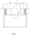
- the machine of the invention consists essentially of a tank 11 suspended over a base 12 with springs 13 between them, associated with a motor-driven vibrator 14, which keeps the whole in vibration during operation.
- the tank 11 contains a treatment channel 15, designed to receive the drying material as well as the articles for treating.
- the drying material may be a granulation of corn shavings, or another suitable product.
- the articles for treatment are those mentioned above.
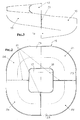
- the channel 15 has a spiral shape which rises from a lower part 16, where the articles for treatment are delivered by means of a chute 17, located in a central loading mouth 18, up to a higher part 19, where the articles are unloaded outside the tank, by means of an exit passage or chute 20, while the drying material is separated from the articles, falling through a grill, as already used elsewhere.
- the channel 15 is defined by a body in stainless steel, consisting of complementary elements made in a die and subsequently joined together by welding 21.
- the channel 15 has a U-shape, with a concave bottom 22 that has a substantially cylindrical surface.
- the channel has straight parts 23 which alternate with and are joined to curved parts 24, to give a configuration that is free of sharp bends and corners.
- the spiral channel 15 has an inclination that varies according to length, with a gradient that increases towards the unloading passage or chute 20, to give the machine greater effectiveness in treating the articles that need drying, polishing and burnishing.
Landscapes
- Engineering & Computer Science (AREA)
- Mechanical Engineering (AREA)
- Finish Polishing, Edge Sharpening, And Grinding By Specific Grinding Devices (AREA)
- Drying Of Solid Materials (AREA)
Abstract
Description
Claims (3)
- Machine for drying, polishing and burnishing cutlery and metal tableware, comprising a tank suspended over a base and moved by a vibrating device, and where said tank is provided with a treatment channel (15), designed to receive a drying material and the articles for treatment, characterised in that said treatment channel (15) rises in a spiral shape from an entrance chute in a loading mouth up to an exit passage or chute for the articles, and has, in transverse cross-section, a U-shaped bottom (22), defined by a substantially concave cylindrical surface and, lengthways, by a series of straight parts (23) that alternate with and are joined to curved parts (24), without sharp bends or corners.
- Machine according to claim 1, in which the spiral treatment channel (15) develops around the loading mouth for the articles and has an inclination that varies in length, with a steeper gradient towards the exit passage or chute.
- Machine according to claims 1 and 2, in which at least the spiral treatment channel (15) consists of stainless steel elements, which have been moulded then joined together by welding.
Applications Claiming Priority (2)
| Application Number | Priority Date | Filing Date | Title |
|---|---|---|---|
| IT2001BS000084U ITBS20010084U1 (en) | 2001-10-18 | 2001-10-18 | MACHINE FOR DRYING, POLISHING AND REGENERATING CUTLERY AND METAL TABLEWARE |
| ITBS20010084 | 2001-10-18 |
Publications (2)
| Publication Number | Publication Date |
|---|---|
| EP1304068A2 true EP1304068A2 (en) | 2003-04-23 |
| EP1304068A3 EP1304068A3 (en) | 2006-03-08 |
Family
ID=11440791
Family Applications (1)
| Application Number | Title | Priority Date | Filing Date |
|---|---|---|---|
| EP02425571A Withdrawn EP1304068A3 (en) | 2001-10-18 | 2002-09-23 | Machine for drying, polishing and burnishing cutlery and metal tableware |
Country Status (3)
| Country | Link |
|---|---|
| US (1) | US6814654B2 (en) |
| EP (1) | EP1304068A3 (en) |
| IT (1) | ITBS20010084U1 (en) |
Cited By (4)
| Publication number | Priority date | Publication date | Assignee | Title |
|---|---|---|---|---|
| EP1523931A1 (en) * | 2003-10-17 | 2005-04-20 | Nicem S.P.A. | Machine with vibrating tank for drying and polishing cutlery |
| EP1491130A3 (en) * | 2003-06-24 | 2005-11-30 | Sammic, S.L. | Drying-polishing machine for cutlery and the like |
| CN103659560A (en) * | 2013-11-20 | 2014-03-26 | 浙江湖磨抛光磨具制造有限公司 | Continuous grinding and drying machine |
| IT201900019580A1 (en) * | 2019-10-22 | 2021-04-22 | Tamai S R L | DRYING-POLISHING CUTLERY MACHINE |
Families Citing this family (28)
| Publication number | Priority date | Publication date | Assignee | Title |
|---|---|---|---|---|
| ES2221762B1 (en) * | 2000-10-19 | 2006-02-16 | Comercial Frucosol, S.A. | DRYING AND GRINDING MACHINE FOR TABLE COVERS AND METAL ARTICLES. |
| US8011129B2 (en) | 2003-06-13 | 2011-09-06 | Battenfeld Technologies, Inc. | Recoil-reducing shooting rest |
| US8621773B2 (en) | 2003-06-13 | 2014-01-07 | Battenfeld Technologies, Inc. | Shooting rests for supporting firearms |
| US7584690B2 (en) | 2004-11-10 | 2009-09-08 | Battenfeld Technologies, Inc. | Firearm vise |
| US7631877B2 (en) | 2006-01-26 | 2009-12-15 | Battenfeld Technologies, Inc. | Firearm targets and methods for manufacturing firearm targets |
| US8104212B2 (en) | 2006-02-24 | 2012-01-31 | Battenfeld Technologies, Inc. | Firearm supports, such as shooting bags, and firearm support assemblies |
| US7681886B2 (en) | 2006-02-24 | 2010-03-23 | Battenfeld Technologies, Inc. | Shooting gallery devices and methods |
| US7726478B2 (en) | 2006-02-27 | 2010-06-01 | Battenfeld Technologies, Inc. | Containers for carrying firearm accessories and/or supporting firearms |
| US7779572B2 (en) | 2006-05-08 | 2010-08-24 | Battenfeld Technologies, Inc. | Bipod device for use with a firearm |
| US8371057B2 (en) | 2006-05-09 | 2013-02-12 | Battenfeld Technologies, Inc. | Firearm cleaning apparatus with protective coating |
| US7883396B2 (en) | 2006-08-21 | 2011-02-08 | Battenfeld Technologies, Inc. | Vibratory tumblers for processing workpieces and methods for packaging and constructing such tumblers |
| WO2008091394A2 (en) | 2006-08-22 | 2008-07-31 | Battenfeld Technologies, Inc. | Adjustable shooting rests and shooting rest assemblies |
| US7774972B2 (en) | 2006-09-11 | 2010-08-17 | Battenfeld Technologies, Inc. | Modular shooting rests and shooting rest assemblies |
| US8296988B2 (en) | 2006-11-30 | 2012-10-30 | Battenfeld Technologies, Inc. | Firearm supporting devices, methods of assembling firearm supporting devices, and methods of packaging firearm supporting devices |
| US7954272B2 (en) | 2007-05-08 | 2011-06-07 | Battenfeld Technologies, Inc. | Adjustable firearm supports and associated methods of use and manufacture |
| US8336708B2 (en) | 2007-07-20 | 2012-12-25 | Battenfeld Technologies, Inc. | System and container for organizing and carrying tools and tool sets |
| US7845267B2 (en) | 2007-09-11 | 2010-12-07 | Battenfield Technologies, Inc. | Attachment mechanisms for coupling firearms to supporting structures |
| US7997021B2 (en) | 2008-11-21 | 2011-08-16 | Battenfeld Technologies | Shooting rests with adjustable height assemblies |
| US8695985B2 (en) | 2011-01-07 | 2014-04-15 | Battenfeld Technologies, Inc. | Stowable shooting target assemblies |
| US8931201B2 (en) | 2012-12-31 | 2015-01-13 | Battenfeld Technologies, Inc. | Gun support apparatus |
| US9993906B1 (en) | 2015-01-19 | 2018-06-12 | Berry's Manufacturing of Utah, Inc. | Vibratory tumbler |
| US9702653B2 (en) | 2015-10-09 | 2017-07-11 | Battenfeld Technologies, Inc. | Firearm shooting rest |
| US10514225B2 (en) | 2018-01-17 | 2019-12-24 | Battenfeld Technologies, Inc. | Firearm shooting rest |
| US10782085B2 (en) | 2019-02-15 | 2020-09-22 | Aob Products Company | Recoil-reducing firearm shooting rest having tank |
| US11841108B2 (en) | 2019-12-17 | 2023-12-12 | Aob Products Company | Multi-legged equipment support having leg angle adjustment |
| CN112192431B (en) * | 2020-10-09 | 2021-07-27 | 揭阳市东拓家居实业有限公司 | Tableware grinding device of stainless steel |
| CN112338775A (en) * | 2020-11-05 | 2021-02-09 | 张家港幸运金属工艺品有限公司 | Gold plating and silver plating tableware polishing equipment who facilitates use |
| US12004658B2 (en) | 2021-04-15 | 2024-06-11 | Aob Products Company | Shooting rest chair |
Family Cites Families (7)
| Publication number | Priority date | Publication date | Assignee | Title |
|---|---|---|---|---|
| US4018009A (en) * | 1975-06-09 | 1977-04-19 | Wheelabrator-Frye, Inc. | Vibratory finishing device |
| EP0029897B1 (en) * | 1979-11-17 | 1983-03-30 | Carl Kurt Walther GmbH & Co. KG | Annular trough shaped vibrating polisher containers |
| IT1229440B (en) * | 1989-06-02 | 1991-08-08 | Rollwasch Italiana Spa | VIBRATION MACHINE PARTICULARLY FOR THE MASS DRYING OF METAL BODIES WITH AUTOMATIC UNLOADING OF THE DRY PIECES. |
| US5117850A (en) * | 1991-04-25 | 1992-06-02 | Delrod Sales Corporation | Device for surface treating of metal parts |
| EP0754529A4 (en) * | 1994-04-01 | 2000-04-05 | Maehashi Ind Co Ltd | Stone corner removing machine |
| IT238331Y1 (en) * | 1997-05-30 | 2000-10-16 | Hyppocampus Srl | MACHINE FOR DRYING, POLISHING AND REGENERATION TREATMENTS DISPOSED AND METAL OBJECTS FROM THE TABLE |
| DE19838540C2 (en) * | 1998-08-25 | 2001-07-26 | Herbert Huettlin | Method for treating a particulate material with a coating medium and device for carrying out such a method |
-
2001
- 2001-10-18 IT IT2001BS000084U patent/ITBS20010084U1/en unknown
-
2002
- 2002-09-23 EP EP02425571A patent/EP1304068A3/en not_active Withdrawn
- 2002-10-10 US US10/268,453 patent/US6814654B2/en not_active Expired - Fee Related
Cited By (5)
| Publication number | Priority date | Publication date | Assignee | Title |
|---|---|---|---|---|
| EP1491130A3 (en) * | 2003-06-24 | 2005-11-30 | Sammic, S.L. | Drying-polishing machine for cutlery and the like |
| EP1523931A1 (en) * | 2003-10-17 | 2005-04-20 | Nicem S.P.A. | Machine with vibrating tank for drying and polishing cutlery |
| CN103659560A (en) * | 2013-11-20 | 2014-03-26 | 浙江湖磨抛光磨具制造有限公司 | Continuous grinding and drying machine |
| CN103659560B (en) * | 2013-11-20 | 2016-09-07 | 浙江湖磨抛光磨具制造有限公司 | A kind of continuously grinding dryer |
| IT201900019580A1 (en) * | 2019-10-22 | 2021-04-22 | Tamai S R L | DRYING-POLISHING CUTLERY MACHINE |
Also Published As
| Publication number | Publication date |
|---|---|
| EP1304068A3 (en) | 2006-03-08 |
| ITBS20010084U1 (en) | 2003-04-18 |
| US6814654B2 (en) | 2004-11-09 |
| US20030077992A1 (en) | 2003-04-24 |
Similar Documents
| Publication | Publication Date | Title |
|---|---|---|
| US6814654B2 (en) | Machine for drying, polishing and burnishing cutlery and metal tableware | |
| EP0882424B1 (en) | Machine for drying, polishing and burnishing cutlery and metal tableware | |
| EP3060079B1 (en) | Buffing expanded foam items | |
| JP2009012085A (en) | Barrel polishing apparatus and barrel polishing method | |
| TWI577521B (en) | Buffing expanded foam items | |
| CN101528352B (en) | Grinding unit with grinding belt and product chamber | |
| JPS63502974A (en) | Multi-stage finishing equipment and method | |
| US20050075058A1 (en) | Sand-belt finishing machine having dust clearing function | |
| US4067147A (en) | Method and apparatus for bowl type vibratory finishing | |
| US20030028989A1 (en) | Ring mesh scrubbing pads | |
| WO2007110728A1 (en) | Washing apparatus for baskets, especially handheld shopping baskets and the like | |
| GB2225522A (en) | Apparatus for abrading small objects | |
| US7958900B2 (en) | Scrubbing machine for cleaning instruments | |
| JPH09511947A (en) | Surface polishing of small objects | |
| JP2003275994A (en) | Method and apparatus for shaping foodstuffs and shaped products | |
| EP1797778A1 (en) | Washing unit particularly for vegetables, with stacked tanks and forced path | |
| JP7153926B2 (en) | Sake brewing rice milling machine | |
| CN102300490A (en) | Devices to reduce waste | |
| US1127634A (en) | Pasteurizer. | |
| EP1491130A2 (en) | Drying-polishing machine for cutlery and the like | |
| KR20160009031A (en) | Easy clean cookware | |
| NL1037020C2 (en) | TOOLS AND METHOD FOR RECONDITIONING A POLISHING PATH, ALSO METHOD FOR MANUFACTURING SUCH A TOOL. | |
| ES2221762B1 (en) | DRYING AND GRINDING MACHINE FOR TABLE COVERS AND METAL ARTICLES. | |
| Stalinskij | Optimal conditions of abrasion cleaning of rolled products | |
| JPS5825836Y2 (en) | Mazu Shiyo's automatic polishing device |
Legal Events
| Date | Code | Title | Description |
|---|---|---|---|
| PUAI | Public reference made under article 153(3) epc to a published international application that has entered the european phase |
Free format text: ORIGINAL CODE: 0009012 |
|
| AK | Designated contracting states |
Designated state(s): AT BE BG CH CY CZ DE DK EE ES FI FR GB GR IE IT LI LU MC NL PT SE SK TR |
|
| AX | Request for extension of the european patent |
Extension state: AL LT LV MK RO SI |
|
| PUAL | Search report despatched |
Free format text: ORIGINAL CODE: 0009013 |
|
| AK | Designated contracting states |
Kind code of ref document: A3 Designated state(s): AT BE BG CH CY CZ DE DK EE ES FI FR GB GR IE IT LI LU MC NL PT SE SK TR |
|
| AX | Request for extension of the european patent |
Extension state: AL LT LV MK RO SI |
|
| RIC1 | Information provided on ipc code assigned before grant |
Ipc: B24B 31/073 20060101ALI20060116BHEP Ipc: A47L 21/02 20060101ALI20060116BHEP Ipc: A47L 19/00 20060101AFI20030206BHEP |
|
| AKX | Designation fees paid | ||
| REG | Reference to a national code |
Ref country code: DE Ref legal event code: 8566 |
|
| STAA | Information on the status of an ep patent application or granted ep patent |
Free format text: STATUS: THE APPLICATION IS DEEMED TO BE WITHDRAWN |
|
| 18D | Application deemed to be withdrawn |
Effective date: 20060909 |