EP1306212A1 - Einrichtung zur Bedruckstoff- und Druckwerkskühlung mittels gekühlter Blasluft an Bogenrotationsdruckmaschinen - Google Patents
Einrichtung zur Bedruckstoff- und Druckwerkskühlung mittels gekühlter Blasluft an Bogenrotationsdruckmaschinen Download PDFInfo
- Publication number
- EP1306212A1 EP1306212A1 EP02022662A EP02022662A EP1306212A1 EP 1306212 A1 EP1306212 A1 EP 1306212A1 EP 02022662 A EP02022662 A EP 02022662A EP 02022662 A EP02022662 A EP 02022662A EP 1306212 A1 EP1306212 A1 EP 1306212A1
- Authority
- EP
- European Patent Office
- Prior art keywords
- cooling
- printing
- devices
- sheet
- blown air
- Prior art date
- Legal status (The legal status is an assumption and is not a legal conclusion. Google has not performed a legal analysis and makes no representation as to the accuracy of the status listed.)
- Granted
Links
- 238000001816 cooling Methods 0.000 title claims abstract description 106
- 238000012546 transfer Methods 0.000 claims abstract description 13
- 239000000463 material Substances 0.000 claims description 15
- 239000000758 substrate Substances 0.000 claims description 8
- 238000011144 upstream manufacturing Methods 0.000 claims description 8
- 239000002826 coolant Substances 0.000 claims description 7
- 238000007664 blowing Methods 0.000 description 6
- 230000005855 radiation Effects 0.000 description 5
- 230000000694 effects Effects 0.000 description 4
- 238000013461 design Methods 0.000 description 3
- 238000009434 installation Methods 0.000 description 3
- 230000010354 integration Effects 0.000 description 3
- 230000000712 assembly Effects 0.000 description 2
- 238000000429 assembly Methods 0.000 description 2
- 238000007599 discharging Methods 0.000 description 2
- 238000001035 drying Methods 0.000 description 2
- 239000000976 ink Substances 0.000 description 2
- 238000000034 method Methods 0.000 description 2
- 238000010521 absorption reaction Methods 0.000 description 1
- 238000005422 blasting Methods 0.000 description 1
- 239000012267 brine Substances 0.000 description 1
- 238000004140 cleaning Methods 0.000 description 1
- 239000011248 coating agent Substances 0.000 description 1
- 238000000576 coating method Methods 0.000 description 1
- 230000006735 deficit Effects 0.000 description 1
- 230000001419 dependent effect Effects 0.000 description 1
- 238000011161 development Methods 0.000 description 1
- 238000010438 heat treatment Methods 0.000 description 1
- 239000004922 lacquer Substances 0.000 description 1
- 239000007788 liquid Substances 0.000 description 1
- 238000013021 overheating Methods 0.000 description 1
- 230000000630 rising effect Effects 0.000 description 1
- HPALAKNZSZLMCH-UHFFFAOYSA-M sodium;chloride;hydrate Chemical compound O.[Na+].[Cl-] HPALAKNZSZLMCH-UHFFFAOYSA-M 0.000 description 1
- 239000000243 solution Substances 0.000 description 1
- 239000002966 varnish Substances 0.000 description 1
- 238000005406 washing Methods 0.000 description 1
- XLYOFNOQVPJJNP-UHFFFAOYSA-N water Substances O XLYOFNOQVPJJNP-UHFFFAOYSA-N 0.000 description 1
Images


Classifications
-
- B—PERFORMING OPERATIONS; TRANSPORTING
- B41—PRINTING; LINING MACHINES; TYPEWRITERS; STAMPS
- B41F—PRINTING MACHINES OR PRESSES
- B41F23/00—Devices for treating the surfaces of sheets, webs, or other articles in connection with printing
- B41F23/04—Devices for treating the surfaces of sheets, webs, or other articles in connection with printing by heat drying, by cooling, by applying powders
- B41F23/0483—Drying combined with cooling
-
- B—PERFORMING OPERATIONS; TRANSPORTING
- B41—PRINTING; LINING MACHINES; TYPEWRITERS; STAMPS
- B41F—PRINTING MACHINES OR PRESSES
- B41F25/00—Devices for pressing sheets or webs against cylinders, e.g. for smoothing purposes
Definitions
- the invention relates to a device for printing material and printing unit cooling by means of cooled blown air on sheet-fed rotary printing presses according to the preamble of the first claim. It is generally known to arrange driers on or between the printing units and in the delivery area to support the drying and curing process of printing inks and in particular lacquers. Large quantities of heat are emitted primarily (infrared dryer) or secondary (UV dryer) to the printing material and the printing machine assemblies adjacent to the dryer.
- the amount of heat given off by convection or radiation and not used for the drying process is considered to be a disturbance for the printing process and the sheet deposit (impairment of the pressure in the subsequent printing unit, excessive stacking temperature, damage to thermally sensitive substrates) and also affects the functioning of neighboring machine elements if they are heat inadmissible.
- all materials in the dryer area must be extremely heat-resistant (cables, hoses, sensors, pneumatic cylinders, etc.).
- a suction device for discharging heated air from the dryer area in the sheet delivery is known, which, however, does not cool the sheet guide surfaces heated by radiation.
- Baffles are described for guiding sheets in the effective range of dryers, on the underside of which coolant channels are arranged (for example DE 19810387 C1).
- their cooling effect is limited to the baffle, cooling of the adjacent machine parts or the substrate cannot be achieved with it.
- the use of cooled blown air for printing plate cooling is known, for example, from EP 0480230 A1 and cylinder cooling by means of blown air from DE 4326835 A1.
- the blown air cooling according to EP 0480230 A1 has a combination of fans and controlled cooler, which is only provided for the pressure plate cooling and is designed as a gap nozzle with a correspondingly small effective range.
- DE 4202544 A1 and DE 4326835 A1 show additional blown air cooling beams with a partial cooling air circuit for rubber or plate cylinders which are not suitable for sheet guiding.
- the mentioned blown air cooling systems have the disadvantages in common that they are additional Require installation space that gives access to the machine assemblies when cleaning or Set-up actions additionally complicate, and they are each only for special cooling tasks designed. In general, the one remaining along the arch path is sufficient Space between dryers, sheet guiding devices, washing devices or car register devices also not out for effective cooling of both the heated machine elements as well as the substrates exposed to the dryers.
- the invention is therefore based on the object of providing a device which is minimal Space requirements for both the substrates and those from the dryers are undesirable with effectively heated machine elements.
- the solution according to the invention uses the existing along the entire arch path pneumatic sheet guide elements before and after the printing zone, below the transfer and Turning drums and in the delivery area through integration of cooling devices for the Cooling air generation and supply to the printing material and the blowing air flowing out for the convective cooling of the heated machine areas, so that substrate and printing machine be effectively cooled along the entire arch path.
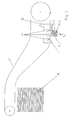
- FIG. 1 shows a schematic representation of the sheet-guiding cylinders of two pressure or Coating units of a sheet-fed rotary printing press in series, between which there are a transfer drum 3 is located. From the upstream printing unit and from the downstream printing unit are only the printing cylinders 2, 4 and those interacting therewith Rubber cylinder 1; 5 shown. Along the arch path are depending Print job and machine configuration arranged pneumatic sheet guiding devices, of which the sheet guiding devices 7, 9, 10, 11 are shown as examples.
- blow box 7 which prevents the printed sheets from smearing on the air cushion plate 8.
- the sheet is smoothly applied to the printing cylinder 4 with the aid of a blow box 9 and, depending on the printing material thickness, of additional blow pipes 10.1, 10.2.
- a UV ink or varnish is applied in the upstream printing unit, then the sheet is dried with the aid of an intermediate dryer 12, which is arranged between printing zone 1, 2 and sheet transfer area 2, 3. It is either an infrared dryer or a UV dryer. It is known from the prior art to provide blown air cooling 11 for cooling the sheet after passing through the dryer 12.
- the cooling device is arranged within blown air boxes in the suction and / or blown air flow from fans or is assigned to the blown air flow from blown pipes and is designed as a cooling register with cooling surfaces through which liquid flows.
- the cooling medium can be water, cooling brine or a gas, the coolant flow being adjustable. With an appropriate design, the cooling surfaces can simultaneously serve as guiding surfaces for the desired blowing air guidance on the sheet guiding device.
- a cooling device 6.1 is arranged in the blown air flow of a fan 6.2 which supplies the air cushion sheet 8 with blown air, the cooling surfaces advantageously being in the form of lamellar air guiding elements according to FIG.
- a cooling device 6.1 can be assigned to each fan 6.2 in a modular manner, these also being connected to one another with their coolant supply and return flows to form a circuit can.
- cooling surfaces In the case of a plurality of fans 6.2 arranged side by side, it may be expedient to to arrange the cooling surfaces next to each other parallel to the sheet transport direction, the outer contour of the cooling surfaces of the shape of the blow box 7 is approximated. Because the cooling surfaces can extend over almost the entire inner volume of the blow box 7, high cooling capacity is therefore transferable.
- Blower tubes 10.1, 10.2 assigned cooling devices 20 have cooling surface rows with coolant channels 21 which extend in the direction of the blasting jet, the cooling surfaces being of compact design due to the small installation space generally available for blowing tubes and their contour being shaped in accordance with the arc path.
- the cooling surfaces also serve as a holder for the blowpipes 10.1, 10.2.
- An arrangement of guide rods 19 in the effective area of cooling surfaces, as shown by way of example for the sheet guiding device 13 after the printing zone 1, 2 has the advantage that they do not have to be cooled by separate cooling (as, for example, according to DE 19829383). Instead of guide rods, cooling surfaces of the cooling device 13.
- FIG. 3 shows a sheet guiding device 15, 16 according to the invention in the delivery directly in the dryer zone 14, which can also be present in several modules.
- a cooling register 15.1 in the blown air flow of a fan 15.2 which supplies blown air to the blow box 16, wherein a plurality of fans 15.2 and cooling register 15.1 can also be arranged in a row at right angles to the transport direction on the blow box 16.
- the dryers 14 above the arch path can be equipped with a suction device 22 for discharging the warm air rising from the dryers 14 and for shielding surrounding printing machine elements before the heat scatter radiation of the dryers 14.
- the blown air cooled in the cooling devices 6.1,9.1,11.1,13.1,15.1 flows through the sheet guiding devices and initially cools the guiding surfaces facing the sheet.
- the air cushion generated outside the sheet guiding devices 6, 9, 11, 13, 15 cools the sheet and the drum or cylinder surface and thus protects the sheet from thermal deformation or damage.
- the surrounding machine elements are also convectively cooled.
- the air box 7 is particularly effective. Due to its expansion, it cools the sheets very effectively and distributes the cooling air evenly before it flows into the neighboring printing units for the purpose of temperature control.
- the exposure time and cooling capacity can thus be increased by a factor of 4 compared to conventional blown air cooling devices.
- the arrangement of the sheet guiding devices 13, 20 according to the invention can furthermore advantageously be chosen according to FIG. 2 in such a way that they shield the cylinder surfaces from heat scatter radiation from the dryers and thus cause an additional, secondary cooling effect.
Landscapes
- Engineering & Computer Science (AREA)
- Mechanical Engineering (AREA)
- Supply, Installation And Extraction Of Printed Sheets Or Plates (AREA)
Abstract
Description
Es ist allgemein bekannt, zur Unterstützung des Trocknungs- und Aushärtungsprozesses von Druckfarben und insbesondere Lacken Trockner an oder zwischen den Druckwerken sowie im Auslagebereich anzuordnen. Dabei werden primär (Infrarot-Trockner) oder sekundär (UV-Trockner) große Wärmemengen an den Bedruckstoff und die an die Trockner angrenzenden Druckmaschinenbaugruppen abgegeben. Die durch Konvektion oder Strahlung abgegebene und nicht für den Trocknungsprozess genutzte Wärmemenge gilt als Störgröße für den Druckprozess und die Bogenablage (Beeinträchtigung des Druckes im nachfolgenden Druckwerk, überhöhte Stapeltemperatur, Beschädigung thermisch sensibler Bedruckstoffe) und beeinträchtigt darüber hinaus die Funktionsweise benachbarter Maschinenelemente, wenn sich diese unzulässig erhitzen. Darüber hinaus müssen sämtliche Materialien im Trocknerwirkungsbereich extrem hitzebeständig ausgeführt sein (Kabel, Schläuche, Sensoren, Pneumatikzylinder usw.).
Zur Bogenführung im Wirkungsbereich von Trocknern werden Leitbleche beschrieben, auf deren Unterseite Kühlmittelkanäle angeordnet sind (z.B. DE 19810387 C1). Allerdings beschränkt sich deren Kühlwirkung nur auf das Leitblech, eine Kühlung auch der angrenzenden Maschinenteile oder des Bedruckstoffes kann damit nicht erreicht werden.
Der Einsatz gekühlter Blasluft zur Druckplattenkühlung ist beispielsweise aus der EP 0480230 A1 bekannt sowie die Zylinderkühlung mittels Blasluft aus der DE 4326835 A1.
Die Blasluftkühlung nach der EP 0480230 A1 weist eine Kombination von Ventilatoren und geregeltem Kühler auf, die nur für die Druckplattenkühlung vorgesehen ist und als Spaltdüse mit dementsprechend geringem Wirkungsbereich ausgebildet ist. Die DE 4202544 A1 und DE 4326835 A1 zeigen zusätzliche Blasluftkühlbalken mit teilweisem Kühlluftkreislauf für Gummi- oder Plattenzylinder, die für eine Bogenführung nicht geeignet sind.
Einzelheiten von Ausführungsformen der Erfindung sind Gegenstand von Unteransprüchen.
- geringer zusätzlicher konstruktiver Aufwand durch die Nutzung vorhandener Bogenleiteinrichtungen
- bessere Kühlwirkung durch Integration von Kühleinrichtungen in die Blasluftkästen unter den Übergabetrommeln, da die unterhalb der Übergabezylinder angesaugte Luft wesentlich kühler als die von bisher üblichen Kühleinrichtungen oberhalb der Druckzylinder angesaugte Luft ist
- Die Kühlluft wird über den zu kühlenden Druckmaschinenbereich aufgrund der Blasluftkühlung über mehrere Bogenleiteinrichtungen gleichmäßiger verteilt
- Einwirkzeit und abgeleiteter Wärmestrom werden um ca. das Vierfache gesteigert.
Es zeigen:
- Fig. 1
- pneumatische Bogenleiteinrichtungen mit Kühleinrichtungen in einem Abschnitt einer Bogenrotationsdruckmaschine in Seitenansicht
- Fig. 2
- Anordnung einer pneumatischen Bogenleiteinrichtung mit Kühleinrichtung nach der Druckzone
- Fig. 3
- Anordnung einer pneumatischen Bogenleiteinrichtung mit Kühleinrichtung in der Bogenauslage
Wenn im vorgeordneten Druckwerk eine UV-Farbe oder ein Lack aufgetragen wird, dann wird der Bogen mit Hilfe eines Zwischentrockners 12, der zwischen Druckzone 1,2 und Bogen-Übergabebereich 2,3 angeordnet ist, getrocknet. Dabei handelt es sich entweder um einen Infrarottrockner oder um einen UV-Trockner. Aus dem Stand der Technik ist es bekannt, zur Abkühlung des Bogens nach dem Passieren des Trockners 12 eine Blasluftkühlung 11 vorzusehen.
Diese reicht jedoch insbesondere bei UV-Trocknern nicht für eine wirksame Bogenkühlung aus und vermag nicht das Aufheizen der den Trockner umgebenden Druckmaschinenbereiche, besonders des Druckzylinders 2 und der Übergabetrommel 3, zu verhindern. Der Wärmestrahlung des Trockners 12 sind aber auch - in Abhängigkeit von der Größe und Anordnung der Blasluftkühlung - der vorgeordnete Gummizylinder 1 und der nachgeordnete Druckzylinder 4 ausgesetzt.
Zur Kühlung der erwärmten Bedruckstoffe und Druckmaschinenelemente sind nun erfindungsgemäß pneumatische Bogenleiteinrichtungen im Wirkungsbereich der Trockner 12 und entlang des weiteren Bogenweges bis hin zur Bogenablage mit einer Kühleinrichtung ausgestattet, die je nach verfügbarem Bauraum und in Abhängigkeit von der Art der Bogenleiteinrichtung ausgebildet sein kann. Die Kühleinrichtung ist dabei innerhalb von Blasluftkästen im Saug- und/oder Blasluftstrom von Ventilatoren angeordnet oder dem Blasluftstrom von Blasrohren zugeordnet und als Kühlregister mit flüssigkeitsdurchströmten Kühlflächen ausgebildet. Das Kühlmedium kann dabei Wasser, Kühlsole oder ein Gas sein, wobei der Kühlmittelstrom regelbar ist. Die Kühlflächen können bei entsprechender Gestaltung gleichzeitig als Leitflächen für die gewünschte Blasluftführung an der Bogenleiteinrichtung dienen.
In einem Blasluftkasten 7 unterhalb der Übergabetrommel 3 ist eine Kühleinrichtung 6.1 im Blasluftstrom eines das Luftpolsterblech 8 mit Blasluft versorgenden Ventilators 6.2 angeordnet, wobei die Kühlflächen in vorteilhafter Weise als lamellenförmige Luftleitelemente gem. Fig.1 ausgebildet sein können, die den vom Ventilator 6.2 kommenden Blasluftstrom gleichmäßig über das Bogenleitblech verteilen und den Luftstrom dabei abkühlen. Wird das Luftpolsterblech 8 von mehreren Ventilatoren 6.2 beaufschlagt oder ist der Blasluftkasten 7 in mehrere Kammern mit jeweils separaten Ventilatoren unterteilt, kann jedem Ventilator 6.2 eine Kühleinrichtung 6.1 modular zugeordnet sein, wobei diese auch untereinander mit ihren Kühlmittelvor- und -rückläufen zu einem Kreislauf verbunden sein können.
Eine Anordnung von Leitstäben 19 im Wirkungsbereich von Kühlflächen, wie beispielhaft für die Bogenleiteinrichtung 13 nach der Druckzone 1,2 dargestellt, besitzt den Vorteil, dass diese nicht durch eine separate Kühlung (wie z.B. gemäß DE 19829383) gekühlt werden müssen. Anstelle von Leitstäben können auch bis zur Bogenbahn verlängerte Kühlflächen der Kühleinrichtung 13.1 vorgesehen sein.
In Fig. 3 ist eine erfindungsgemäße Bogenleiteinrichtung 15,16 in der Auslage unmittelbar in der Trocknerzone 14 dargestellt, die auch in mehreren Modulen vorhanden sein kann. Analog zum Blaskasten 7 in Fig. 1 befindet sich erfindungsgemäß ein Kühlregister 15.1 im Blasluftstrom eines den Blaskasten 16 mit Blasluft beaufschlagenden Ventilators 15.2, wobei auch mehrere Ventilatoren 15.2 und Kühlregister 15.1 in einer Reihe rechtwinklig zur Transportrichtung am Blaskasten 16 angeordnet sein können.
Die Trockner 14 oberhalb des Bogenweges können zur Ableitung der von den Trocknern 14 aufsteigenden Warmluft und zur Abschirmung umliegender Druckmaschinenelemente vor der Wärmestreustrahlung der Trockner 14 mit einer Absaugvorrichtung 22 ausgestattet sein.
Die Anordnung der erfindungsgemäßen Bogenleiteinrichtungen 13,20 kann weiterhin gemäß Fig.2 in vorteilhafter Weise so gewählt werden, dass sie die Zylinderoberflächen vor Wärmestreustrahlungen der Trockner abschirmen und somit noch einen zusätzlichen, sekundären Kühleffekt bewirken.
- 1
- vorgeordneter Gummizylinder
- 2
- vorgeordneter Druckzylinder
- 3
- Übergabetrommel
- 4
- nachgeordneter Druckzylinder
- 5
- nachgeordneter Gummizylinder
- 6
- Blasluftkühlung für Blaskasten 7
- 6.1
- Kühleinrichtung im Blasluftstrom des Ventilators 6.2
- 6.2
- Ventilator, Ventilatoren
- 6.3
- Kühleinrichtung im Saugluftstrom des Ventilators 6.2
- 7
- Blaskasten
- 8
- Luftpolsterblech
- 9
- Blaskasten
- 9.1
- Kühleinrichtung im Blasluftstrom des Ventilators 9.2
- 9.2
- Ventilator, Ventilatoren
- 9.3
- Kühleinrichtung im Saugluftstrom des Ventilators 6.2
- 10.1
- Blasrohr
- 10.2
- Blasrohr
- 11
- Bogenleiteinrichtung
- 11.1
- Kühleinrichtung im Blasluftstrom des Ventilators 11.2
- 11.2
- Ventilator, Ventilatoren
- 11.3
- Kühleinrichtung im Saugluftstrom des Ventilators 11.2
- 12
- Trockner
- 13
- Bogenleiteinrichtung
- 13.1
- Kühleinrichtung im Blasluftstrom des Ventilators 13.2
- 13.2
- Ventilator, Ventilatoren
- 13.3
- Kühleinrichtung im Saugluftstrom des Ventilators 13.2
- 14
- Trockner im Auslagebereich
- 15
- Blasluftkühlung für den Blaskasten 16
- 15.1
- Kühleinrichtung im Blasluftstrom des Ventilators 15.2
- 15.2
- Ventilator, Ventilatoren
- 15.3
- Kühleinrichtung im Saugluftstrom des Ventilators 15.2
- 16
- Blaskasten
- 17
- Bogenauslage
- 18
- Bogenstapel
- 19
- Leitstäbe
- 20
- Kühlflächen
- 21
- Kühlmittelkanäle
- 22
- Absaugvorrichtung
Claims (10)
- Einrichtung zur Bedruckstoff- und Druckwerkskühlung mittels gekühlter Blasluft an Bogenrotationsdruckmaschinen, die mit Trocknern ausgestattetet sind, mit pneumatischen Bogenleiteinrichtungen in unmittelbarer Nähe des Bogenförderweges und mit Kühleinrichtungen für die zugeführte Blasluft
dadurch gekennzeichnet, dassdie gekühlte Blasluft über eine oder mehrere für die für die pneumatische Bogenführung vorgesehenen Bogenleiteinrichtungen (6,9,10.1,10.2,11,13,15) entlang des Bogenförderweges zugeführt wirddie Kühleinrichtungen (6.1,6.3,9.1,9.3,11.1,11.3,13.1,13.3,15.1,15.3,20) im Strömungsquerschnitt der Blasluft an oder in den Bogenleiteinrichtungen (6,9,10.1,10.2,11,13,15) angeordnet sind. - Einrichtung zur Bedruckstoff- und Druckwerkskühlung nach Anspruch 1, dadurch gekennzeichnet, dass die Kühleinrichtungen (6.1,6.3,9.1,9.3,11.1,11.3,13.1, 13.3,15.1, 15.3,20) durch mit Kühlmittel durchflossene Kühlflächen im Strömungsquerschnitt für die Blasluft gebildet werden.
- Einrichtung zur Bedruckstoff- und Druckwerkskühlung nach Anspruch 1 oder 2, dadurch gekennzeichnet, dass die Kühleinrichtungen (6.1,6.3,9.1,9.3,11.1,11.3,13.1, 13.3,15.1,15.3,20) in Blaskästen (7,9,11,13,16) und/oder an Blasrohren (10.1,10.2) unterhalb von Übergabetrommeln (3) und/oder oberhalb von Druckzylindern (2,4) angeordnet sind.
- Einrichtung zur Bedruckstoff- und Druckwerkskühlung nach Anspruch 3, dadurch gekennzeichnet, dass Kühleinrichtungen (15.1,15.3) in Bogenleiteinrichtungen (15) im Auslagebereich angeordnet sind.
- Einrichtung zur Bedruckstoff- und Druckwerkskühlung nach Anspruch 3 oder 4 , dadurch gekennzeichnet, dass zusätzliche Bogenleiteinrichtungen (11,13) mit Kühleinrichtungen (11.1,11.3,13.1,13.3) zur intensiveren Kühlung entlang des Bogenweges angeordnet sind.
- Einrichtung zur Bedruckstoff- und Druckwerkskühlung nach einem der Ansprüche 1 bis 5, dadurch gekennzeichnet, dass die Kühlflächen (6.3,9.3,11.3,13.3,15.3) im Ansaugstrom vor Ventilatoren (6.2,9.2,11.2,13.2,15.2) oder anderen Druckerzeugern angeordnet sind.
- Einrichtung zur Bedruckstoff- und Druckwerkskühlung nach einem der Ansprüche 1 bis 5, dadurch gekennzeichnet, dass die Kühlflächen (6.1,9.1,11.1,13.1,15.1,20) im Blasluftstrom nach Ventilatoren (6.2,9.2,11.2,13.2,15.2) oder anderen Druckerzeugern (10.1,10.2) angeordnet sind.
- Einrichtung zur Bedruckstoff- und Druckwerkskühlung nach einem der Ansprüche 1 bis 5 mit Kühlflächen nach Anspruch 6 und 7.
- Einrichtung zur Bedruckstoff- und Druckwerkskühlung nach einem der Ansprüche 1 bis 8, dadurch gekennzeichnet, dass oberhalb der Trockner (12,14) die Kühlung unterstützende Absaugvorrichtungen (22) angeordnet sind.
- Einrichtung zur Bedruckstoff- und Druckwerkskühlung nach Anspruch 3, dadurch gekennzeichnet, dass die Bogenleiteinrichtungen (13,20) zwischen Trockner (12) und vorgeordneter Druckzone (1,2) bzw. vor der nachgeordneten Druckzone (4,5) in den Ausbreitungsrichtungen der reflektierten Wärmestreustrahlen der Trockner (12) derart angeordnet sind, dass der vorgeordnete Gummizylinder (1) und nachgeordnete Druckzylinder (4) von den Wärmestrahlen des Trockners abgeschirmt werden.
Applications Claiming Priority (2)
| Application Number | Priority Date | Filing Date | Title |
|---|---|---|---|
| DE10152593 | 2001-10-24 | ||
| DE10152593A DE10152593A1 (de) | 2001-10-24 | 2001-10-24 | Einrichtung zur Bedruckstoff- und Druckwerkskühlung mittels gekühlter Blasluft an Bogenrotationsdruckmaschinen |
Publications (2)
| Publication Number | Publication Date |
|---|---|
| EP1306212A1 true EP1306212A1 (de) | 2003-05-02 |
| EP1306212B1 EP1306212B1 (de) | 2010-05-19 |
Family
ID=7703634
Family Applications (1)
| Application Number | Title | Priority Date | Filing Date |
|---|---|---|---|
| EP02022662A Expired - Lifetime EP1306212B1 (de) | 2001-10-24 | 2002-10-10 | Einrichtung zur Bedruckstoff- und Druckwerkskühlung mittels gekühlter Blasluft an Bogenrotationsdruckmaschinen |
Country Status (3)
| Country | Link |
|---|---|
| US (1) | US6983696B2 (de) |
| EP (1) | EP1306212B1 (de) |
| DE (2) | DE10152593A1 (de) |
Cited By (4)
| Publication number | Priority date | Publication date | Assignee | Title |
|---|---|---|---|---|
| EP1555122A1 (de) | 2004-01-16 | 2005-07-20 | Uviterno AG | Verfahren zum Bedrucken von Flachmaterial und Vorrichtung zur Durchführung des Verfahrens |
| CN103342249A (zh) * | 2013-07-16 | 2013-10-09 | 成都印钞有限公司 | 一种印刷纸张吸风展平装置 |
| DE102017004053A1 (de) | 2017-04-26 | 2018-10-31 | Giesecke+Devrient Currency Technology Gmbh | Verhindern einer Übertragung frischer Druckfarbe auf die Rückseite anderer Bögen beim Bogenstichtiefdruck |
| DE102005042956B4 (de) | 2004-10-06 | 2019-04-25 | Heidelberger Druckmaschinen Ag | Druckmaschine |
Families Citing this family (13)
| Publication number | Priority date | Publication date | Assignee | Title |
|---|---|---|---|---|
| DE10334657A1 (de) | 2003-07-30 | 2005-02-17 | Koenig & Bauer Ag | Verfahren und Einrichtung zur Bedruckstoff- und Druckmaschinenkühlung |
| JP2005125739A (ja) * | 2003-10-27 | 2005-05-19 | Heidelberger Druckmas Ag | 乾燥機を備えた枚葉紙印刷機 |
| US20050211442A1 (en) * | 2004-03-29 | 2005-09-29 | Mcguire Bob | System and method for low-pressure well completion |
| JP2006297734A (ja) * | 2005-04-20 | 2006-11-02 | Komori Corp | 印刷機のエア吹き装置 |
| DE602005005349T2 (de) * | 2005-12-22 | 2008-06-26 | Tapematic S.P.A. | Ein Gerät zum Trocknen durch Strahlung |
| JP5089357B2 (ja) * | 2006-12-11 | 2012-12-05 | ハイデルベルガー ドルツクマシーネン アクチエンゲゼルシヤフト | 印刷機で印刷または塗工された枚葉紙を乾かす方法 |
| US8118420B2 (en) | 2007-12-21 | 2012-02-21 | Palo Alto Research Center Incorporated | Contactless ink leveling method and apparatus |
| JP2009220954A (ja) * | 2008-03-17 | 2009-10-01 | Fujifilm Corp | インクジェット記録装置、インクジェット記録方法 |
| JP4963683B2 (ja) * | 2008-03-31 | 2012-06-27 | 富士フイルム株式会社 | インクジェット記録装置 |
| US8807736B1 (en) | 2013-01-31 | 2014-08-19 | Ricoh Company, Ltd. | Low-temperature gas flow insertion in printing system dryers |
| US9605898B2 (en) | 2013-03-07 | 2017-03-28 | Ricoh Company, Ltd. | Drum temperature control for a radiant dryer of a printing system |
| WO2015137973A1 (en) | 2014-03-14 | 2015-09-17 | Hewlett-Packard Development Company, L. P. | Drying media |
| JP6087032B2 (ja) * | 2014-09-19 | 2017-03-01 | 富士フイルム株式会社 | 画像形成装置 |
Citations (8)
| Publication number | Priority date | Publication date | Assignee | Title |
|---|---|---|---|---|
| EP0246100A2 (de) * | 1986-05-14 | 1987-11-19 | Wallace Knight Limited | Einrichtung zur Verhinderung der Ablösung einer Bahn oder eines Bogens von einem drehenden Zylinder |
| EP0480230A1 (de) | 1990-10-08 | 1992-04-15 | MAN Roland Druckmaschinen AG | Thermoregeler für eine um einen Druckformzylinder gelegte Druckform für wasserlosen Offset-Druck |
| DE9214459U1 (de) | 1992-10-26 | 1993-02-04 | Weitmann & Konrad GmbH & Co KG, 7022 Leinfelden-Echterdingen | Vorrichtung zum thermischen Trocknen von Materialbahnen, -bögen o.dgl. |
| DE4202544A1 (de) | 1992-01-30 | 1993-08-05 | Baldwin Gegenheimer Gmbh | Druckplatten-temperierungssystem fuer eine druckmaschine |
| DE9310028U1 (de) | 1993-07-06 | 1993-11-04 | Kba-Planeta Ag, 01445 Radebeul | Bedruckstoffkühlung in Auslegern von Bogenrotationsdruckmaschinen |
| DE4326835A1 (de) | 1993-08-10 | 1995-02-16 | Baldwin Gegenheimer Gmbh | Temperierungssystem für Druckmaschinenzylinder |
| DE19810387C1 (de) | 1998-03-11 | 1999-07-29 | Autz & Herrmann Maschf | Bogenleiteinrichtung |
| WO2001032423A1 (en) | 1999-10-29 | 2001-05-10 | Daniel Bostrack | Print cylinder cooling system |
Family Cites Families (21)
| Publication number | Priority date | Publication date | Assignee | Title |
|---|---|---|---|---|
| US3900959A (en) * | 1973-05-07 | 1975-08-26 | Minnesota Mining & Mfg | Combined infra-red and air flow drying for photographic film |
| DE3113750A1 (de) * | 1981-04-04 | 1982-10-14 | Heidelberger Druckmaschinen Ag, 6900 Heidelberg | "bogenausleger fuer rotationsdruckmaschinen mit an endlosen ketten umlaufenden greiferbruecken" |
| JPS62153073A (ja) * | 1985-07-08 | 1987-07-08 | Olympus Optical Co Ltd | 画像記録装置 |
| US4811493A (en) * | 1987-08-05 | 1989-03-14 | Burgio Joseph T Jr | Dryer-cooler apparatus |
| DE4307732A1 (de) * | 1993-03-11 | 1994-09-15 | Baldwin Gegenheimer Gmbh | Temperierungsvorrichtung für Rotationskörper in Druckwerken |
| DE4308276C2 (de) * | 1993-03-16 | 1997-09-04 | Heidelberger Druckmasch Ag | Leiteinrichtung für einen Bogen |
| DE4322324C2 (de) * | 1993-07-05 | 2002-01-17 | Heidelberger Druckmasch Ag | Bogentransport und Bogenführung im Auslagebereich von Rotationsdruckmaschinen |
| EP0652104B1 (de) | 1993-11-05 | 2002-04-10 | MAN Roland Druckmaschinen AG | Druckwerk für wasserlosen Offsetdruck |
| DE4433644B4 (de) * | 1994-09-21 | 2005-03-03 | Heidelberger Druckmaschinen Ag | Verfahren und Vorrichtung zur Führung eines Bogens |
| DE9418358U1 (de) * | 1994-11-17 | 1995-02-23 | L.T.S.-Trocknungsverfahren GmbH, 65719 Hofheim | Bogenleiteinrichtung |
| DE19503110B4 (de) * | 1995-02-01 | 2009-01-29 | Heidelberger Druckmaschinen Ag | Bogenleiteinrichtung für Druckmaschinen |
| US6378425B1 (en) * | 1995-02-01 | 2002-04-30 | Heidelberger Druckmaschinen Ag | Sheet-guiding device for printing presses |
| DE19513426C2 (de) | 1995-04-08 | 2002-07-11 | Koenig & Bauer Ag | Verfahren und Einrichtung zum Leiten von Bogen |
| DE19602514C1 (de) * | 1996-01-25 | 1997-04-03 | Heidelberger Druckmasch Ag | Bogenleitvorrichtung mit einem gekühlten Bogenleitblech |
| DE19651406C1 (de) * | 1996-12-11 | 1998-06-10 | Roland Man Druckmasch | Trocknereinheit in einer Druckmaschine |
| DE19701230C1 (de) * | 1997-01-16 | 1998-02-19 | Roland Man Druckmasch | Pneumatische Bogenleiteinrichtung in einer Druckmaschine |
| DE19716424B4 (de) | 1997-04-18 | 2004-08-26 | Koenig & Bauer Ag | Einrichtung zum Vermeiden des Ablegens von Farbe auf Zylindern von Druckmaschinen |
| DE29824606U1 (de) | 1997-08-19 | 2001-10-25 | Cleanpack GmbH Innovative Verpackungen, 27432 Bremervörde | Vorrichtung zum Trocknen von mit metallhaltigen und nicht metallhaltigen Farben bedruckter Kunststoff-Folienbahnen |
| DE29816734U1 (de) * | 1998-09-18 | 1998-12-03 | MAN Roland Druckmaschinen AG, 63075 Offenbach | Pneumatische Bogenleiteinrichtung in einer Druckmaschine |
| DE19842740C2 (de) | 1998-09-18 | 2002-11-07 | Roland Man Druckmasch | Pneumatische Bogenleiteinrichtung in einer Druckmaschine |
| DE10042887A1 (de) * | 2000-08-31 | 2002-03-14 | Heidelberger Druckmasch Ag | Maschine zur Verarbeitung von Bogen |
-
2001
- 2001-10-24 DE DE10152593A patent/DE10152593A1/de not_active Withdrawn
-
2002
- 2002-10-10 DE DE50214439T patent/DE50214439D1/de not_active Expired - Lifetime
- 2002-10-10 EP EP02022662A patent/EP1306212B1/de not_active Expired - Lifetime
- 2002-10-17 US US10/273,198 patent/US6983696B2/en not_active Expired - Fee Related
Patent Citations (8)
| Publication number | Priority date | Publication date | Assignee | Title |
|---|---|---|---|---|
| EP0246100A2 (de) * | 1986-05-14 | 1987-11-19 | Wallace Knight Limited | Einrichtung zur Verhinderung der Ablösung einer Bahn oder eines Bogens von einem drehenden Zylinder |
| EP0480230A1 (de) | 1990-10-08 | 1992-04-15 | MAN Roland Druckmaschinen AG | Thermoregeler für eine um einen Druckformzylinder gelegte Druckform für wasserlosen Offset-Druck |
| DE4202544A1 (de) | 1992-01-30 | 1993-08-05 | Baldwin Gegenheimer Gmbh | Druckplatten-temperierungssystem fuer eine druckmaschine |
| DE9214459U1 (de) | 1992-10-26 | 1993-02-04 | Weitmann & Konrad GmbH & Co KG, 7022 Leinfelden-Echterdingen | Vorrichtung zum thermischen Trocknen von Materialbahnen, -bögen o.dgl. |
| DE9310028U1 (de) | 1993-07-06 | 1993-11-04 | Kba-Planeta Ag, 01445 Radebeul | Bedruckstoffkühlung in Auslegern von Bogenrotationsdruckmaschinen |
| DE4326835A1 (de) | 1993-08-10 | 1995-02-16 | Baldwin Gegenheimer Gmbh | Temperierungssystem für Druckmaschinenzylinder |
| DE19810387C1 (de) | 1998-03-11 | 1999-07-29 | Autz & Herrmann Maschf | Bogenleiteinrichtung |
| WO2001032423A1 (en) | 1999-10-29 | 2001-05-10 | Daniel Bostrack | Print cylinder cooling system |
Cited By (6)
| Publication number | Priority date | Publication date | Assignee | Title |
|---|---|---|---|---|
| EP1555122A1 (de) | 2004-01-16 | 2005-07-20 | Uviterno AG | Verfahren zum Bedrucken von Flachmaterial und Vorrichtung zur Durchführung des Verfahrens |
| DE102005042956B4 (de) | 2004-10-06 | 2019-04-25 | Heidelberger Druckmaschinen Ag | Druckmaschine |
| CN103342249A (zh) * | 2013-07-16 | 2013-10-09 | 成都印钞有限公司 | 一种印刷纸张吸风展平装置 |
| CN103342249B (zh) * | 2013-07-16 | 2016-08-10 | 成都印钞有限公司 | 一种印刷纸张吸风展平装置 |
| DE102017004053A1 (de) | 2017-04-26 | 2018-10-31 | Giesecke+Devrient Currency Technology Gmbh | Verhindern einer Übertragung frischer Druckfarbe auf die Rückseite anderer Bögen beim Bogenstichtiefdruck |
| WO2018197039A1 (de) | 2017-04-26 | 2018-11-01 | Giesecke+Devrient Currency Technology Gmbh | Verhindern einer übertragung frischer druckfarbe auf die rückseite anderer bögen beim bogenstichtiefdruck |
Also Published As
| Publication number | Publication date |
|---|---|
| US6983696B2 (en) | 2006-01-10 |
| DE50214439D1 (de) | 2010-07-01 |
| EP1306212B1 (de) | 2010-05-19 |
| US20030121440A1 (en) | 2003-07-03 |
| DE10152593A1 (de) | 2003-05-08 |
Similar Documents
| Publication | Publication Date | Title |
|---|---|---|
| EP1306212B1 (de) | Einrichtung zur Bedruckstoff- und Druckwerkskühlung mittels gekühlter Blasluft an Bogenrotationsdruckmaschinen | |
| DE69415622T2 (de) | Hochgeschwindigkeitslufttrockner und Absaugvorrichtung | |
| EP0847855B1 (de) | Trocknereinheit in einer Druckmaschine | |
| EP4244067B1 (de) | Bogendruckmaschine mit einem von einer non-impact-druckeinrichtung bedruckte bogen trocknenden trockner | |
| EP2463100B1 (de) | Bogen verarbeitende Maschine, insbesondere Bogendruckmaschine | |
| EP3788313B1 (de) | Verfahren zum trocknen eines substrats sowie lufttrocknermodul sowie trocknersystem | |
| DE19905095C2 (de) | Bogenführungseinrichtung für eine Druckmaschine | |
| DE10141755B4 (de) | Trocknungsvorrichtung zur Strahlungstrocknung | |
| DE19521442A1 (de) | Leiteinrichtung für bedruckte Bogen und/oder Bahnen in Trocknersystemen | |
| EP4098447B1 (de) | Verarbeitungsmaschine mit einer trocknungsvorrichtung und verfahren zum betreiben einer trocknungsvorrichtung | |
| DE102018200260A1 (de) | Maschine zum Bedrucken von Bedruckstoffbogen mit Tinte | |
| DE102018210836A1 (de) | Vorrichtung zum Bedrucken und Trocknen von Bedruckstoff | |
| EP1502738B1 (de) | Verfahren und Einrichtung zur Bedruckstoff- und Druckmaschinenkühlung | |
| EP1834912B1 (de) | Bogenverarbeitungsmaschine mit einer Leiteinrichtung zum schwebenden Führen von Bogenmaterial | |
| DE102022124767A1 (de) | Vorrichtung zum Trocknen von Bedruckstoff | |
| WO2021214128A1 (de) | Verfahren zum trocknen eines bestrahlungsguts und infrarot-bestrahlungsvorrichtung zur durchführung des verfahrens | |
| DE102021123678A1 (de) | Trocknungseinrichtung in einer Druckmaschine und Druckmaschine mit dieser Trocknungseinrichtung | |
| WO2004035313A1 (de) | Trockner für eine materialbahn | |
| DE102024106682B4 (de) | Vorrichtung zur Wärmebehandlung einer Warenbahn | |
| DE102016201480B4 (de) | Vorrichtung und Verfahren zum Trocknen eines Bandmaterials einer Druckmaschine | |
| DE29819402U1 (de) | Bogenleiteinrichtung in einer Druckmaschine | |
| EP3647056B1 (de) | Maschine zum herstellen von druckprodukten | |
| DE10144159A1 (de) | Bogenleiteinrichtung | |
| EP0743178A2 (de) | Leiteinrichtung für bedruckte Bogen und/oder Bahnen in Trocknersystemen | |
| DE102018209539A1 (de) | Befeuchtungsvorrichtung in einer Druckmaschine |
Legal Events
| Date | Code | Title | Description |
|---|---|---|---|
| PUAI | Public reference made under article 153(3) epc to a published international application that has entered the european phase |
Free format text: ORIGINAL CODE: 0009012 |
|
| 17P | Request for examination filed |
Effective date: 20030225 |
|
| AK | Designated contracting states |
Designated state(s): AT BE BG CH CY CZ DE DK EE ES FI FR GB GR IE IT LI LU MC NL PT SE SK TR |
|
| AX | Request for extension of the european patent |
Extension state: AL LT LV MK RO SI |
|
| AKX | Designation fees paid |
Designated state(s): DE FR GB IT |
|
| GRAP | Despatch of communication of intention to grant a patent |
Free format text: ORIGINAL CODE: EPIDOSNIGR1 |
|
| GRAS | Grant fee paid |
Free format text: ORIGINAL CODE: EPIDOSNIGR3 |
|
| GRAA | (expected) grant |
Free format text: ORIGINAL CODE: 0009210 |
|
| AK | Designated contracting states |
Kind code of ref document: B1 Designated state(s): DE FR GB IT |
|
| REG | Reference to a national code |
Ref country code: GB Ref legal event code: FG4D Free format text: NOT ENGLISH |
|
| REF | Corresponds to: |
Ref document number: 50214439 Country of ref document: DE Date of ref document: 20100701 Kind code of ref document: P |
|
| PLBE | No opposition filed within time limit |
Free format text: ORIGINAL CODE: 0009261 |
|
| STAA | Information on the status of an ep patent application or granted ep patent |
Free format text: STATUS: NO OPPOSITION FILED WITHIN TIME LIMIT |
|
| 26N | No opposition filed |
Effective date: 20110222 |
|
| REG | Reference to a national code |
Ref country code: DE Ref legal event code: R097 Ref document number: 50214439 Country of ref document: DE Effective date: 20110221 |
|
| PGFP | Annual fee paid to national office [announced via postgrant information from national office to epo] |
Ref country code: FR Payment date: 20121031 Year of fee payment: 11 |
|
| PGFP | Annual fee paid to national office [announced via postgrant information from national office to epo] |
Ref country code: IT Payment date: 20121025 Year of fee payment: 11 Ref country code: GB Payment date: 20121019 Year of fee payment: 11 |
|
| GBPC | Gb: european patent ceased through non-payment of renewal fee |
Effective date: 20131010 |
|
| PG25 | Lapsed in a contracting state [announced via postgrant information from national office to epo] |
Ref country code: GB Free format text: LAPSE BECAUSE OF NON-PAYMENT OF DUE FEES Effective date: 20131010 |
|
| REG | Reference to a national code |
Ref country code: FR Ref legal event code: ST Effective date: 20140630 |
|
| PG25 | Lapsed in a contracting state [announced via postgrant information from national office to epo] |
Ref country code: IT Free format text: LAPSE BECAUSE OF NON-PAYMENT OF DUE FEES Effective date: 20131010 Ref country code: FR Free format text: LAPSE BECAUSE OF NON-PAYMENT OF DUE FEES Effective date: 20131031 |
|
| REG | Reference to a national code |
Ref country code: DE Ref legal event code: R081 Ref document number: 50214439 Country of ref document: DE Owner name: KOENIG & BAUER AG, DE Free format text: FORMER OWNER: KOENIG & BAUER AKTIENGESELLSCHAFT, 97080 WUERZBURG, DE |
|
| PGFP | Annual fee paid to national office [announced via postgrant information from national office to epo] |
Ref country code: DE Payment date: 20151208 Year of fee payment: 14 |
|
| REG | Reference to a national code |
Ref country code: DE Ref legal event code: R119 Ref document number: 50214439 Country of ref document: DE |
|
| PG25 | Lapsed in a contracting state [announced via postgrant information from national office to epo] |
Ref country code: DE Free format text: LAPSE BECAUSE OF NON-PAYMENT OF DUE FEES Effective date: 20170503 |