EP1306235B1 - Procédé et appareil pour détecter une baisse de pression dans un pneumatique - Google Patents
Procédé et appareil pour détecter une baisse de pression dans un pneumatique Download PDFInfo
- Publication number
- EP1306235B1 EP1306235B1 EP02023808A EP02023808A EP1306235B1 EP 1306235 B1 EP1306235 B1 EP 1306235B1 EP 02023808 A EP02023808 A EP 02023808A EP 02023808 A EP02023808 A EP 02023808A EP 1306235 B1 EP1306235 B1 EP 1306235B1
- Authority
- EP
- European Patent Office
- Prior art keywords
- rotational information
- wheels
- sided
- decompression
- vehicle
- Prior art date
- Legal status (The legal status is an assumption and is not a legal conclusion. Google has not performed a legal analysis and makes no representation as to the accuracy of the status listed.)
- Expired - Lifetime
Links
Images


Classifications
-
- B—PERFORMING OPERATIONS; TRANSPORTING
- B60—VEHICLES IN GENERAL
- B60C—VEHICLE TYRES; TYRE INFLATION; TYRE CHANGING; CONNECTING VALVES TO INFLATABLE ELASTIC BODIES IN GENERAL; DEVICES OR ARRANGEMENTS RELATED TO TYRES
- B60C23/00—Devices for measuring, signalling, controlling, or distributing tyre pressure or temperature, specially adapted for mounting on vehicles; Arrangement of tyre inflating devices on vehicles, e.g. of pumps or of tanks; Tyre cooling arrangements
- B60C23/06—Signalling devices actuated by deformation of the tyre, e.g. tyre mounted deformation sensors or indirect determination of tyre deformation based on wheel speed, wheel-centre to ground distance or inclination of wheel axle
- B60C23/061—Signalling devices actuated by deformation of the tyre, e.g. tyre mounted deformation sensors or indirect determination of tyre deformation based on wheel speed, wheel-centre to ground distance or inclination of wheel axle by monitoring wheel speed
Definitions
- the present invention relates to a method and apparatus for detecting decrease in tire air-pressure and a program for judging decompression of a tire. More particularly, it relates to a method and apparatus for detecting decrease in tire air-pressure and a program for judging decompression of a tire with which it is possible to detect simultaneous decompression of two wheel tires on the same side of a four-wheeled vehicle or simultaneous decompression of both front tires or both rear tires while it is further possible to detect decompression of a single wheel tire.
- An apparatus for detecting decrease in tire air-pressure (DWS) in which decompression of a tire is detected on the basis of rotational (wheel speed) information of four wheel tires attached to a vehicle is conventionally known.
- the apparatus employs a theory that a rotational velocity or a rotational angular velocity of a compressed tire is increased when compared to remaining normal tires owing to a decrease in outer diameter (dynamic load radius of the tire) from that of a tire of normal internal pressure.
- a method for detecting decrease in internal pressure on the basis of a relative difference in rotational angular velocities of tires reference should be made to Japanese Unexamined Patent Publication No.
- DEL F ⁇ 1 + F ⁇ 4 / 2 - F ⁇ 2 + F ⁇ 3 / 2 / ⁇ F ⁇ 1 + F ⁇ 4 + F ⁇ 3 + F ⁇ 4 / 4 ⁇ ⁇ 100 % is employed as a judged value DEL.
- F1 to F4 denote rotational angular velocities of a front left tire, a front right tire, a rear left tire and a rear right tire, respectively.
- Document EP 0 489 563 discloses a method according to the preamble of claims 1-6.
- a method for detecting decrease in tire air-pressure in which decrease in internal pressure of a tire is detected on the basis of rotational information obtained from tires attached to a vehicle.
- the method includes the steps of: detecting rotational information of the respective tires; storing the rotational information of the respective tires; comparing rotational information of all left-sided wheels and rotational information of all right-sided wheels of the vehicle when the vehicle is performing straight-ahead running; and judging simultaneous decompression of all left-sided wheels or simultaneous decompression of all right-sided wheels on the basis of only a relationship between a value obtained through comparison of the left-sided and right-sided rotational information and a specified threshold.
- an apparatus for detecting decrease in tire air-pressure in which decrease in internal pressure of a tire is detected on the basis of rotational information obtained from tires attached to a vehicle.
- the apparatus includes: rotational information detecting means adapted for detecting rotational information of the respective tires; a rotational information storing means adapted for storing the rotational information of the respective tires; a comparing means for comparing rotational information of all left-sided wheels and rotational information of all right-sided wheels of the vehicle when the vehicle is performing straight-ahead running; and a decompression judging means adapted for judging simultaneous decompression of all left-sided wheels or simultaneous decompression of all right-sided wheels on the basis of only a relationship between a value obtained through comparison of the left-sided and right-sided rotational information and a specified threshold.
- a computer program comprising source code means adapted for judging decompression of a tire, in which for judging decrease in tire air-pressure of a tire, a computer is made to function as a rotational information storing means for storing the rotational information of the respective tires; a comparing means for comparing rotational information of all left-sided wheels and rotational information of all right-sided wheels of the vehicle when the vehicle is performing straight-ahead running; and a decompression judging means for judging simultaneous decompression of all left-sided wheels or simultaneous decompression of all right-sided wheels on the basis of only a relationship between a value obtained through comparison of the left-sided and right-sided rotational information and a specified threshold.
- a method for detecting decrease in tire air-pressure in which decrease in internal pressure of a tire is detected on the basis of rotational information obtained from tires attached to a vehicle.
- the method includes the steps of: detecting rotational information of the respective tires; storing the rotational information of the respective tires; comparing rotational information of both front wheels and rotational information of both rear wheels of the vehicle when the vehicle is performing straight-ahead running and neither driving nor braking force is acting on the tires; and judging simultaneous decompression of both front wheels or simultaneous decompression of both rear wheels on the basis of only a relationship between a value obtained through comparison of the rotational information of both front wheels and the rotational information of both rear wheels and a specified threshold.
- an apparatus for detecting decrease in tire air-pressure in which decrease in internal pressure of a tire is detected on the basis of rotational information obtained from tires attached to a vehicle.
- the apparatus includes: rotational information detecting means adapted for detecting rotational information of the respective tires; a rotational information storing means adapted for storing the rotational information of the respective tires; a comparing means adapted for comparing rotational information of both front wheels and rotational information of both rear wheels of the vehicle when the vehicle is performing straight-ahead running and neither driving nor braking force is acting on the tires; and a decompression judging means adapted for judging simultaneous decompression of both front wheels or simultaneous decompression of both rear wheels on the basis of only a relationship between a value obtained through comparison of the rotational information of both front wheels and the rotational information of both rear wheels and a specified threshold.
- a computer program comprising source code means adapted for judging decompression of a tire, in which for judging decrease in tire air-pressure of a tire, a computer is made to function as a rotational information storing means for storing the rotational information of the respective tires; a comparing means for comparing rotational information of both front wheels and rotational information of both rear wheels of the vehicle when the vehicle is performing straight-ahead running and neither driving nor braking force is acting on the tires; and a decompression judging means for judging simultaneous decompression of both front wheels or simultaneous decompression of both rear wheels on the basis of only a relationship between a value obtained through comparison of the rotational information of both front wheels and the rotational information of both rear wheels and a specified threshold.
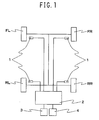
- Fig. 1 is a block view showing Embodiment 1 of the apparatus for detecting decrease in tire air-pressure according to the present invention
- the rotational information detecting means 1 might be a wheel speed sensor for measuring a wheel speed (rotational velocity) on the basis of number of pulses upon generating rotational pulses by using an electromagnetic pickup or similar or an angular velocity sensor in which power is generated through rotation such as in a dynamo, wherein the wheel speeds are measured from a voltage thereof.
- Outputs of the rotational information detecting means 1 are supplied to a control unit 2 which might be a computer such as an ABS.
- a display 3 comprising liquid crystal elements, plasma display elements or CRT for informing a tire Wi of which the tire air-pressure has decreased and an initializing switch 4 which might be operated by a driver are connected to the control unit 2.
- the control unit 2 comprises an I/O interface 2a required for sending/receiving signals to/from an external device, a CPU 2b which functions as a center of calculation, a ROM 2c which stores therein a control operation program for the CPU 2b, and a RAM 2d into which data are temporally written and are read out therefrom when the CPU 2b performs control operations.
- Pulse signals corresponding to the rotational number of tires Wi are output from the rotational information detecting means 1.
- Embodiment 1 it is possible to judge decompression of a single wheel tire from among four wheel tires as well as to judge simultaneous decompression of both left-sided or right-sided wheel tires in order to improve accuracy of judging decompression.
- the threshold for judging decompression is set to be a threshold for judging simultaneous decompression of 30 % of both left-sided or right-sided wheel tires, it is possible to judge decompression of a single tire by 60 %.
- the apparatus of Embodiment 1 includes a rotational information detecting means 1 for detecting rotational information of respective tires Wi, a rotational information storing means for storing the rotational information of the respective tires Wi; a comparing means for comparing rotational information of all left-sided wheels and rotational information of all right-sided wheels of the vehicle when the vehicle is performing straight-ahead running; and a decompression judging means for judging decompression on the basis of a relationship between a value obtained through comparison of the left-sided and right-sided rotational information and a specified threshold.
- Embodiment 1 will be explained on the basis of a case in which the value obtained through comparison is an amount of fluctuation in ratios.
- the program for judging decompression of a tire according to Embodiment 1 is so arranged that the control unit 2 is made to function as the rotational information storing means for storing the rotational information of the respective tires Wi; the comparing means for comparing rotational information of all left-sided wheels and rotational information of all right-sided wheels of the vehicle when the vehicle is performing straight-ahead running; and the decompression judging means for judging decompression on the basis of a relationship between a value obtained through comparison of the left-sided and right-sided rotational information and a specified threshold.
- Step S1 It is determined whether the vehicle is running straight-ahead or not (Step S1). For performing this determination, it is possible to employ information of a steering angle sensor.
- a steering angle sensor When the condition of running straight-ahead is met, sums of respective rotational wheel speeds on the right side and the left side of the vehicle (VR, VL) are respectively obtained (Steps S2, S3). Then, a ratio of rotational wheel speeds on the right side and the left side (VL/VR) is obtained (Step S4). Defining this ratio as VRATIO, the VRATIO will ordinarily approximate to 1 when the tires are at normal internal pressure since the rotational information speed on the right side and the rotational information speed on the left side will become substantially identical.
- Step S5 an absolute value of an amount of fluctuation in the ratio of the rotational wheel speeds with respect to 1 (1 - VRATIO) is obtained. It is then determined whether the absolute value DVRATIO exceeds a specified threshold, for instance, 0.002 (Step S6), and if the value is not less than 0.002, it is determined that two wheel tires on the same side are simultaneously decompressed (Step S7).
- a specified threshold for instance, 0.002
- a FF (front engine/front drive) vehicle attached with summer tires of normal internal pressure (2.2 ⁇ 10 5 Pa) was provided.
- the tire size of the tires was 185/70R14.
- a running condition for the vehicle was a condition in which the vehicle was made to run on a straight course at a constant speed (50 km/h) with 2 persons riding thereon.
- the vehicle was made to run at the above running conditions upon decompressing the air-pressure of the front left wheel tire and the rear left wheel tire (both wheel tires on the left side) by 25 %, respectively.
- Wheel speed ratios of front and rear wheels DLR, wheel speed ratios of right-sided and left-sided wheels DFR (VRATIO) and wheel speed ratios of sums of diagonally located wheels DEL were respectively obtained for Examples 1 and 2. The results are shown in Figs. 4 and 5 .
- Embodiment 2 of the present invention will now be explained.
- Embodiment is so arranged that it is capable of judging decompression of a single wheel tire from among four wheel tires while it is also capable of judging simultaneous decompression of both front wheels or simultaneous decompression of both rear wheels for improving accuracy of judging decompression as same as Embodiment 1.
- the threshold for judging decompression is set to be a threshold for judging simultaneous decompression of 25 % of both front or of both rear wheel tires, it is possible to judge decompression of a single tire by 50 %.
- the apparatus of Embodiment 2 includes rotational information detecting means 1 for detecting rotational information of respective tires Wi, a rotational information storing means for storing the rotational information of the respective tires Wi; a comparing means for comparing rotational information of both front wheels and rotational information of both rear wheels of the vehicle when the vehicle is performing straight-ahead running and neither driving nor braking force is acting on the tires; and a decompression judging means for judging simultaneous decompression of both front wheels or simultaneous decompression of both rear wheels on the basis of a relationship between a value obtained through comparison of the rotational information of both front wheels and the rotational information of both rear wheels and a specified threshold.
- the value obtained through comparison might be a difference besides an amount of fluctuation in ratios.
- Embodiment 2 will be explained on the basis of a case in which the value obtained through comparison is an amount of fluctuation in ratios.
- the program for judging decompression of a tire according to Embodiment 2 is so arranged that the control unit 2 is made to function as the rotational information storing means for storing the rotational information of the respective tires Wi; the comparing means for comparing rotational information of both front wheels and rotational information of both rear wheels of the vehicle when the vehicle is performing straight-ahead running and neither driving nor braking force is acting on the tires; and the decompression judging means for judging simultaneous decompression of both front wheels or simultaneous decompression of both rear wheels on the basis of a relationship between a value obtained through comparison of the rotational information of both front wheels and the rotational information of both rear wheels and a specified threshold.
- Step S11 It is determined whether the vehicle is running straight-ahead or not and whether any driving or braking force is applied to the tires or not. For performing this determination, it is determined that the vehicle is driving straight ahead (condition 1) by utilizing information of, for instance, a steering sensor, and that neither driving nor braking force is acting on the tires (condition 2) upon comparing torque information as calculated by an apparatus for controlling running conditions of a vehicle such as an ABS with a preliminarily defined threshold. Then, when both of the conditions 1 and 2 are met, sums of respective rotational wheel speeds of both front wheels and both rear wheels of the vehicle (VF, VR) are respectively obtained (Steps S12, S13).
- a ratio of rotational wheel speeds of the front wheels and the rear wheels (VF/VR) is obtained (Step S14).
- VRATIO a ratio of rotational wheel speeds of the front wheels and the rear wheels
- the VRATIO will ordinarily approximate to 1 when the tires are at normal internal pressure since the rotational information speeds of the front and rear wheels will become substantially identical.
- VRATIO will depart from 1.
- an absolute value of an amount of fluctuation in the ratio of the rotational wheel speeds with respect to 1 (1-VRATIO) is obtained (Step S15).
- Step S16 It is then determined whether the absolute value DVRATIO exceeds a specified threshold, for instance, 0.003 (Step S16), and if the value is not less than 0.003, it is determined that both front wheels or both rear wheels are simultaneously decompressed (Step S17).
- a specified threshold for instance, 0.003
- the threshold might be set by using data preliminarily obtained through tests in which running was performed in a decompressed state.
- the vehicle was made to run under the same conditions as those of Example 1 upon decompressing the air-pressure of both front tires by 25 %, respectively.
- Wheel speed ratios of front and rear wheels DLR (VRATIO), wheel speed ratios of right-sided and left-sided (same-sided) wheels DFR, and wheel speed ratios of sums of diagonally located wheels DEL were respectively obtained for Examples 1 and 3. The results are shown in Figs. 4 and 7 .
Landscapes
- Engineering & Computer Science (AREA)
- Mechanical Engineering (AREA)
- Measuring Fluid Pressure (AREA)
Claims (6)
- Procédé pour détecter une baisse de pression d'air dans le pneu, dans lequel la baisse de pression interne d'un pneu est détectée en fonction de l'information de rotation obtenue des pneus fixés à un véhicule, le procédé comprenant les étapes consistant à : détecter l'information de rotation des pneus respectifs ; stocker l'information de rotation des pneus respectifs ; comparer l'information de rotation de toutes les roues gauches et l'information de rotation de toutes les roues droites du véhicule lorsque le véhicule roule en ligne droite ; caractérisé par l'étape consistant à juger la décompression simultanée de toutes les roues gauches ou la décompression simultanée de toutes les roues droites uniquement en fonction d'une relation entre une valeur obtenue par comparaison de l'information de rotation du côté gauche et du côté droit et un seuil spécifié.
- Appareil pour détecter la baisse de pression d'air dans le pneu, dans lequel la baisse de pression interne d'un pneu est détectée en fonction de l'information de rotation obtenue des pneus fixés à un véhicule, l'appareil comprenant : des moyens de détection d'information de rotation (1) adaptés pour détecter l'information de rotation des pneus respectifs ; des moyens de stockage d'information de rotation adaptés pour stocker l'information de rotation des pneus respectifs ; des moyens de comparaison adaptés pour comparer l'information de rotation de toutes les roues gauches et l'information de rotation de toutes les roues droites du véhicule lorsque le véhicule roule en ligne droite ; caractérisé par des moyens de jugement de décompression adaptés pour juger la décompression simultanée de toutes les roues gauches ou la décompression simultanée de toutes les roues droites uniquement en fonction d'une relation entre une valeur obtenue par la comparaison de l'information de rotation du côté gauche et du côté droit et un seuil spécifié.
- Programme informatique comprenant des moyens de code source adaptés pour juger la décompression d'un pneu, dans lequel pour juger la baisse de pression d'air dans le pneu, on prévoit un ordinateur pour fonctionner en tant que moyen de stockage d'information de rotation afin de stocker l'information de rotation des pneus respectifs ; des moyens de comparaison pour comparer l'information de rotation de toutes les roues gauches et l'information de rotation de toutes les roues droites du véhicule lorsque le véhicule roule en ligne droite ; caractérisé par des moyens de jugement de décompression pour juger la décompression simultanée de toutes les roues gauches ou la décompression simultanée de toutes les roues droites uniquement en fonction d'une relation entre une valeur obtenue par la comparaison de l'information de rotation du côté gauche et du côté droit et un seuil spécifié.
- Procédé pour détecter une baisse de pression d'air dans le pneu, dans lequel la baisse de pression interne d'un pneu est détectée en fonction de l'information de rotation obtenue des pneus fixés à un véhicule, le procédé comprenant les étapes consistant à : détecter l'information de rotation des pneus respectifs ; stocker l'information de rotation des pneus respectifs ; comparer l'information de rotation des deux roues avant et l'information de rotation des deux roues arrière du véhicule lorsque le véhicule roule en ligne droite et ni la force d'entraînement ni la force de freinage n'agit sur les pneus ; caractérisé par l'étape consistant à juger la décompression simultanée des deux roues avant ou la décompression simultanée des deux roues arrière uniquement en fonction d'une relation entre une valeur obtenue par la comparaison de l'information de rotation des deux roues avant et l'information de rotation des deux roues arrière et un seuil spécifié.
- Appareil pour détecter la baisse de pression d'air dans le pneu, dans lequel la baisse de pression interne d'un pneu est détectée en fonction de l'information de rotation obtenue des pneus fixés à un véhicule, l'appareil comprenant : des moyens de détection d'information de rotation (1) adaptés pour détecter l'information de rotation des pneus respectifs ; des moyens de stockage d'information de rotation adaptés pour stocker l'information de rotation des pneus respectifs ; des moyens de comparaison adaptés pour comparer l'information de rotation des deux roues avant et l'information de rotation des deux roues arrière du véhicule lorsque le véhicule roule en ligne droite et ni la force d'entraînement ni la force de freinage n'agit sur les pneus ; caractérisé par des moyens de jugement de décompression adaptés pour juger la décompression simultanée des deux roues avant ou la décompression simultanée des deux roues arrière uniquement en fonction d'une relation entre une valeur obtenue par la comparaison de l'information de rotation des deux roues avant et l'information de rotation des deux roues arrière et un seuil spécifié.
- Programme informatique comprenant des moyens de code source adaptés pour juger la décompression d'un pneu, dans lequel pour juger la baisse de pression d'air d'un pneu, on prévoit un ordinateur pour fonctionner en tant que moyen de stockage d'information de rotation afin de stocker l'information de rotation des pneus respectifs ; des moyens de comparaison pour comparer l'information de rotation des deux roues avant et l'information de rotation des deux roues arrière du véhicule lorsque le véhicule roule en ligne droite et ni la force d'entraînement ni la force de freinage n'agit sur les pneus ; caractérisé par des moyens de jugement de décompression pour juger une décompression simultanée des deux roues avant ou la décompression simultanée des deux roues arrière uniquement en fonction d'une relation entre une valeur obtenue par la comparaison de l'information de rotation des deux roues avant et l'information de rotation des deux roues arrière et un seuil spécifié.
Applications Claiming Priority (4)
| Application Number | Priority Date | Filing Date | Title |
|---|---|---|---|
| JP2001327868A JP2003127627A (ja) | 2001-10-25 | 2001-10-25 | タイヤ空気圧低下検出方法および装置、ならびにタイヤ減圧判定のプログラム |
| JP2001327868 | 2001-10-25 | ||
| JP2001365049A JP2003165318A (ja) | 2001-11-29 | 2001-11-29 | タイヤ空気圧低下検出方法および装置、ならびにタイヤ減圧判定のプログラム |
| JP2001365049 | 2001-11-29 |
Publications (2)
| Publication Number | Publication Date |
|---|---|
| EP1306235A1 EP1306235A1 (fr) | 2003-05-02 |
| EP1306235B1 true EP1306235B1 (fr) | 2009-02-11 |
Family
ID=26624106
Family Applications (1)
| Application Number | Title | Priority Date | Filing Date |
|---|---|---|---|
| EP02023808A Expired - Lifetime EP1306235B1 (fr) | 2001-10-25 | 2002-10-23 | Procédé et appareil pour détecter une baisse de pression dans un pneumatique |
Country Status (3)
| Country | Link |
|---|---|
| US (1) | US6831553B2 (fr) |
| EP (1) | EP1306235B1 (fr) |
| DE (1) | DE60231098D1 (fr) |
Families Citing this family (7)
| Publication number | Priority date | Publication date | Assignee | Title |
|---|---|---|---|---|
| US8266465B2 (en) | 2000-07-26 | 2012-09-11 | Bridgestone Americas Tire Operation, LLC | System for conserving battery life in a battery operated device |
| US7161476B2 (en) | 2000-07-26 | 2007-01-09 | Bridgestone Firestone North American Tire, Llc | Electronic tire management system |
| JP3769459B2 (ja) * | 2000-10-13 | 2006-04-26 | 株式会社豊田中央研究所 | タイヤバースト予測装置 |
| WO2002068226A1 (fr) * | 2001-02-26 | 2002-09-06 | Toyota Jidosha Kabushiki Kaisha | Appareil de mesure de l'etat d'un pneumatique et appareil de determination d'un etat anormal de pneumatique |
| JP2002248916A (ja) * | 2001-02-26 | 2002-09-03 | Toyota Motor Corp | タイヤ情報取得装置、タイヤ情報取得方法およびタイヤ情報取得プログラム |
| JP2009255711A (ja) * | 2008-04-16 | 2009-11-05 | Sumitomo Rubber Ind Ltd | タイヤ空気圧低下検出方法及び装置、並びにタイヤ減圧判定のプログラム |
| JP7726144B2 (ja) * | 2022-07-14 | 2025-08-20 | トヨタ自動車株式会社 | 情報処理装置、それを備えた車両、情報処理方法およびプログラム |
Family Cites Families (10)
| Publication number | Priority date | Publication date | Assignee | Title |
|---|---|---|---|---|
| GB9026558D0 (en) * | 1990-12-06 | 1991-01-23 | Sumitomo Rubber Ind | Method of detecting a deflated tyre on a vehicle |
| GB9109466D0 (en) * | 1991-05-02 | 1991-06-26 | Sumitomo Rubber Ind | A method of detecting a deflated tyre on a vehicle |
| JP2780887B2 (ja) | 1992-01-31 | 1998-07-30 | 本田技研工業株式会社 | 車両のタイヤ空気圧判定装置 |
| JP3286415B2 (ja) | 1993-08-05 | 2002-05-27 | マツダ株式会社 | タイヤ空気圧警報装置 |
| JP3286414B2 (ja) | 1993-08-05 | 2002-05-27 | マツダ株式会社 | タイヤ空気圧警報装置 |
| JP3159575B2 (ja) | 1993-08-16 | 2001-04-23 | マツダ株式会社 | タイヤ空気圧警報装置 |
| JP2746341B2 (ja) * | 1993-11-02 | 1998-05-06 | 本田技研工業株式会社 | 車輪減圧判定装置 |
| JP3045957B2 (ja) | 1995-02-01 | 2000-05-29 | 住友電気工業株式会社 | タイヤ空気圧低下警報装置 |
| US5604307A (en) * | 1995-02-01 | 1997-02-18 | Sumitomo Rubber Industries, Ltd. | Tire pressure drop alarm device sensing partial travel on irregular road surface |
| JP3344919B2 (ja) * | 1997-03-07 | 2002-11-18 | 住友電気工業株式会社 | タイヤ空気圧低下検出装置 |
-
2002
- 2002-10-23 EP EP02023808A patent/EP1306235B1/fr not_active Expired - Lifetime
- 2002-10-23 DE DE60231098T patent/DE60231098D1/de not_active Expired - Lifetime
- 2002-10-25 US US10/280,060 patent/US6831553B2/en not_active Expired - Lifetime
Also Published As
| Publication number | Publication date |
|---|---|
| EP1306235A1 (fr) | 2003-05-02 |
| DE60231098D1 (de) | 2009-03-26 |
| US6831553B2 (en) | 2004-12-14 |
| US20030080863A1 (en) | 2003-05-01 |
Similar Documents
| Publication | Publication Date | Title |
|---|---|---|
| EP1167086B1 (fr) | Appareil et procédé concernant la détection d'une baisse de pression dans un pneumatique | |
| EP0908331B1 (fr) | Appareil et procédé concernant la détection d'une baisse de pression dans un pneumatique | |
| EP1352765B1 (fr) | Procédé et appareil concernant la détection d'une baisse de pression dans un pneumatique, et programme pour juger la décompression du pneumatique | |
| EP1190874B1 (fr) | Appareil et procédé concernant la détection d'une baisse de pression dans un pneumatique | |
| EP1396356B1 (fr) | Procédé et appareil concernant la détection d'une baisse de pression dans un pneumatique, et programme pour juger la décompression du pneumatique | |
| EP1327536B1 (fr) | Procédé et appareil concernant la détection d'une baisse de pression dans un pneumatique, et programme pour juger la décompression du pneumatique | |
| EP1270278B1 (fr) | Appareil et procédé concernant la détection d'une baisse de pression dans un pneumatique, et programme pour juger la décompression pour un vehicule à deux roues | |
| EP1306235B1 (fr) | Procédé et appareil pour détecter une baisse de pression dans un pneumatique | |
| EP1332895B1 (fr) | Appareil et procédé concernant la détection d'une baisse de pression dans un pneumatique | |
| US6501373B2 (en) | Apparatus and method for alarming decrease in tire air-pressure | |
| EP1361081B1 (fr) | Procédé et appareil concernant la détection d'une baisse de pression dans un pneumatique, et programme pour juger la décompression du pneumatique | |
| EP1371507B1 (fr) | Procédé et appareil de détection d'une baisse de pression dans un pneumatique, et pour juger la décompression du pneumatique | |
| EP1284205B1 (fr) | Procédé et appareil pour la détection d'une baisse de pression dans un pneumatique, et programme de sélection des seuils pour juger de la décompression d'un pneumatique | |
| US6907327B2 (en) | Method of detection of limited slip differential device, method and apparatus for detecting decrease in tire air-pressure employing the method of detection, and program for judging decompression of tire | |
| US7395145B2 (en) | Apparatus and method for calculating initial correction coefficient, and program for calculating initial correction coefficient | |
| US6945102B2 (en) | Method and apparatus for detecting decrease in tire air-pressure and program for judging decompression of tire | |
| JP2004017717A (ja) | タイヤ空気圧低下検出方法および装置、ならびにタイヤ減圧判定のプログラム | |
| JP2008018940A (ja) | タイヤ空気圧低下検出方法および装置、ならびにタイヤ減圧判定のプログラム | |
| JP3050026B2 (ja) | タイヤ空気圧低下検出方法 | |
| JP2003165318A (ja) | タイヤ空気圧低下検出方法および装置、ならびにタイヤ減圧判定のプログラム | |
| JP2004203302A (ja) | タイヤ空気圧低下検出方法および装置、ならびに減圧タイヤ特定のプログラム |
Legal Events
| Date | Code | Title | Description |
|---|---|---|---|
| PUAI | Public reference made under article 153(3) epc to a published international application that has entered the european phase |
Free format text: ORIGINAL CODE: 0009012 |
|
| AK | Designated contracting states |
Designated state(s): AT BE BG CH CY CZ DE DK EE ES FI FR GB GR IE IT LI LU MC NL PT SE SK TR |
|
| AX | Request for extension of the european patent |
Extension state: AL LT LV MK RO SI |
|
| AKX | Designation fees paid | ||
| 17P | Request for examination filed |
Effective date: 20031103 |
|
| RBV | Designated contracting states (corrected) |
Designated state(s): DE FR GB |
|
| REG | Reference to a national code |
Ref country code: DE Ref legal event code: 8566 |
|
| GRAP | Despatch of communication of intention to grant a patent |
Free format text: ORIGINAL CODE: EPIDOSNIGR1 |
|
| GRAS | Grant fee paid |
Free format text: ORIGINAL CODE: EPIDOSNIGR3 |
|
| GRAA | (expected) grant |
Free format text: ORIGINAL CODE: 0009210 |
|
| AK | Designated contracting states |
Kind code of ref document: B1 Designated state(s): DE FR GB |
|
| REG | Reference to a national code |
Ref country code: GB Ref legal event code: FG4D |
|
| REF | Corresponds to: |
Ref document number: 60231098 Country of ref document: DE Date of ref document: 20090326 Kind code of ref document: P |
|
| PLBE | No opposition filed within time limit |
Free format text: ORIGINAL CODE: 0009261 |
|
| STAA | Information on the status of an ep patent application or granted ep patent |
Free format text: STATUS: NO OPPOSITION FILED WITHIN TIME LIMIT |
|
| 26N | No opposition filed |
Effective date: 20091112 |
|
| PG25 | Lapsed in a contracting state [announced via postgrant information from national office to epo] |
Ref country code: GB Free format text: LAPSE BECAUSE OF NON-PAYMENT OF DUE FEES Effective date: 20091023 |
|
| REG | Reference to a national code |
Ref country code: FR Ref legal event code: PLFP Year of fee payment: 15 |
|
| REG | Reference to a national code |
Ref country code: FR Ref legal event code: PLFP Year of fee payment: 16 |
|
| REG | Reference to a national code |
Ref country code: FR Ref legal event code: PLFP Year of fee payment: 17 |
|
| PGFP | Annual fee paid to national office [announced via postgrant information from national office to epo] |
Ref country code: DE Payment date: 20181009 Year of fee payment: 17 |
|
| REG | Reference to a national code |
Ref country code: DE Ref legal event code: R119 Ref document number: 60231098 Country of ref document: DE |
|
| PG25 | Lapsed in a contracting state [announced via postgrant information from national office to epo] |
Ref country code: DE Free format text: LAPSE BECAUSE OF NON-PAYMENT OF DUE FEES Effective date: 20200501 |
|
| PGFP | Annual fee paid to national office [announced via postgrant information from national office to epo] |
Ref country code: FR Payment date: 20200914 Year of fee payment: 19 |
|
| PG25 | Lapsed in a contracting state [announced via postgrant information from national office to epo] |
Ref country code: FR Free format text: LAPSE BECAUSE OF NON-PAYMENT OF DUE FEES Effective date: 20211031 |