EP1306867A1 - Improvements made to fuse-holder bases - Google Patents
Improvements made to fuse-holder bases Download PDFInfo
- Publication number
- EP1306867A1 EP1306867A1 EP01931701A EP01931701A EP1306867A1 EP 1306867 A1 EP1306867 A1 EP 1306867A1 EP 01931701 A EP01931701 A EP 01931701A EP 01931701 A EP01931701 A EP 01931701A EP 1306867 A1 EP1306867 A1 EP 1306867A1
- Authority
- EP
- European Patent Office
- Prior art keywords
- handle
- cover
- fuse
- foreseen
- covers
- Prior art date
- Legal status (The legal status is an assumption and is not a legal conclusion. Google has not performed a legal analysis and makes no representation as to the accuracy of the status listed.)
- Granted
Links
- 230000006872 improvement Effects 0.000 title claims description 17
- 230000000903 blocking effect Effects 0.000 claims abstract description 26
- 238000006073 displacement reaction Methods 0.000 claims description 12
- 210000003739 neck Anatomy 0.000 claims description 8
- 210000002445 nipple Anatomy 0.000 claims description 6
- 241000935974 Paralichthys dentatus Species 0.000 claims description 4
- 238000000605 extraction Methods 0.000 claims description 3
- 230000014759 maintenance of location Effects 0.000 claims description 3
- 239000004020 conductor Substances 0.000 claims description 2
- 230000000694 effects Effects 0.000 claims 1
- 230000000284 resting effect Effects 0.000 claims 1
- 230000008878 coupling Effects 0.000 abstract description 2
- 238000010168 coupling process Methods 0.000 abstract description 2
- 238000005859 coupling reaction Methods 0.000 abstract description 2
- 230000000295 complement effect Effects 0.000 description 4
- 230000008859 change Effects 0.000 description 3
- 238000003780 insertion Methods 0.000 description 2
- 230000037431 insertion Effects 0.000 description 2
- 230000000717 retained effect Effects 0.000 description 2
- 125000006850 spacer group Chemical group 0.000 description 2
- 230000009471 action Effects 0.000 description 1
- 230000003100 immobilizing effect Effects 0.000 description 1
- 238000010348 incorporation Methods 0.000 description 1
- 230000007246 mechanism Effects 0.000 description 1
- 241000894007 species Species 0.000 description 1
- 238000006467 substitution reaction Methods 0.000 description 1
Images


Classifications
-
- H—ELECTRICITY
- H01—ELECTRIC ELEMENTS
- H01H—ELECTRIC SWITCHES; RELAYS; SELECTORS; EMERGENCY PROTECTIVE DEVICES
- H01H33/00—High-tension or heavy-current switches with arc-extinguishing or arc-preventing means
- H01H33/02—Details
- H01H33/04—Means for extinguishing or preventing arc between current-carrying parts
- H01H33/12—Auxiliary contacts on to which the arc is transferred from the main contacts
- H01H33/121—Load break switches
-
- H—ELECTRICITY
- H01—ELECTRIC ELEMENTS
- H01H—ELECTRIC SWITCHES; RELAYS; SELECTORS; EMERGENCY PROTECTIVE DEVICES
- H01H31/00—Air-break switches for high tension without arc-extinguishing or arc-preventing means
- H01H31/02—Details
- H01H31/12—Adaptation for built-in fuse
- H01H31/122—Fuses mounted on, or constituting the movable contact parts of, the switch
Definitions
- the present invention relates to a series of improvements introduced in the fuse-holder bases with single phase, three-phase or under-load disconnection, in which the fusible cartridge employed is of the type "NH", the improvements affecting both the cover and the handle associated with said cover, and which as a whole form the fuse-holder base mounted in an appropriate casing.
- the object of the invention is to provide a fuse-holder base which incorporates a series of improvements with respect to the traditional bases, which not only provide greater safety for the operatives in charge of making the connections and disconnections, but also offer high versatility and efficacy in their operation and even a remarkable facility and simplicity in the respective manipulations to carried out for connecting/disconnecting and for the assembly/disassembly of the elements (fuses or other pieces) which it is sometimes necessary to change or to replace.
- Fuse-holder bases generally comprise a socket which is connected to the respective conductor bars, which socket is related with a casing on which are mounted the actual fuse-holder covers, in which the cartridges or fuses are obviously secured and retained.
- Said covers can occupy an operating or closed position in which the connection is established, or a non-operating or open position which corresponds to that of fuse disconnection. In the non-operating position, the replacement of deteriorated fuses can be carried out, as well as the assembly/disassembly, both of the latter and of other pieces which could be damaged and exchange or substitution thereof is required.
- each fuse comes mounted in its own fuse-holder cover, it being possible to carry out the opening in an individual way (single-phase opening) or the three covers at the same time (three-phase opening).
- each one of the fuse-holder covers has an individual handle, so that to carry out three-phase openings, that is the three fuses at the same time, elements and/or mechanisms are used which connect the three individual handles to each other, or else a single element by means of which the simultaneous opening of the three covers is carried out.
- Fuse-holder bases of the referenced type are described in the documents corresponding to the European Patents 0508291: 1045414; as well as in the German Patents 4307495 and 4435828.
- the improvements of the invention affect the fuse-holder covers and the corresponding handles, being conceived to obtain fuse-holder bases which are more versatile, simple and easy to manipulate.
- fuse-holder cover is incorporated in such a way that it admits the assembly or incorporation indistinctly of a fixed handle, of a concealed handle or even a system of three-phase disconnection.
- the cover mentioned also incorporates means of mounting and securing the fuse which are accessible from the exterior of the cover thereby facilitating the assembly and disassembly operations of the fuses.
- the fixed handle and the concealed handle are constituted by a U-shaped profile, by way of a bridge the side arms of which are mounted on the cover by sliding in some rebates foreseen in the sides of the aforementioned cover, the side arms of the handles having a free edge which is finished off in an oblique fold toward the interior and of spherical surface.
- This spherical surface is complementary with another spherical surface foreseen in the lower part of the side rebates of the cover, in such a way that the handle can rotate on the surfaces which causes a flange foreseen in one of its side edges to lodge in a channel foreseen in one of the internal edges of the rebates on the sides of the cover. In this way it is achieved that the union between the handle and the cover to be an union which through its form allows the sudden forces in short-circuit closing operations to be better withstood.
- the fixed handle also has on its side arms some internal pawls which are located in some notches foreseen on the front part of the cover, in correspondence with the corners which form the side rebates for assembly of the handle, in such a way that the union of the pawls on the notches render impossible the disassembling of the fixed handle.
- the concealable handle is free of the interlocking pawls foreseen on the fixed handle in order to allow the sliding toward the front and toward the back of the actual handle, for the purpose that the latter can occupy the frontward operating or salient position and the backward retracted or concealed position which corresponds to the non-operating position.
- the referenced concealed handle has on the edges of its sides a pair of intermediate notches and another pair of notches in ramp form in the proximity of the transversal branch of the handle, so that the first pair of notches is foreseen to block the handle in operating position, when the edges engage in them of individual sliding blocking pieces mounted in some front recesses of the cover, these blocking pieces being pushed outward by a species of spring in order to engage in the referenced notches, in such way that a manual displacement of such blocking pieces toward the interior allows these to be released from the referenced notches, making possible the sliding of the handle in order to occupy the non-operating position.
- the referenced cover has on its front part a hand-operated sliding piece, which has a rear leg folded back on itself, determining a web by way of a spring which allows through deformation and elasticity the passage of a laminar portion or lug pertaining to the fuse, so that the latter will be retained on the cover by means of the blocking action exercised by the referenced leg of the front sliding piece, once such leg has been surpassed by the lug of the fuse, all this in a manner such that to release the fuse it will be sufficient to displace the sliding piece laterally, causing the leg to be displaced with respect to the lug and cease to constitute an obstacle for the latter, allowing the extraction of the fuse with respect to the cover.
- Another characteristic of innovation or improvement of the invention consists of some means which interconnect two bases each carrying a fuse in parallel, which means are constituted by a pair of threaded pins which pass through respective facing holes foreseen for this end in the contiguous sides of the handles corresponding to the two covers, these being blocked by means of respective nuts threaded on both ends of said pins, said means being supplemented with respective spacer sleeves mounted on the pins and inserted between the two contiguous sides of the two referenced handles.
- Another improvement of the invention consists of the form of manipulating the three fuse-holder bases to perform the simultaneous disconnecting of the three phases, consisting in that the three covers are connected in a pivoting manner to two common side bars, joined transversally by means of a pair of handles.
- the pivoting assembly of the bars to the cover is made by means of some nipples with cotter foreseen in the bars, which are housed in respective cylindrical necks foreseen in the respective covers, all this in such a manner that these can pivot with respect to the bars to perform the disconnection and/or connection, although their detaching with respect to the bars is impeded by virtue of the cotter means incorporated in the nipples and necks in which they are housed.
- Another characteristic of innovation consists of a means of blocking the covers, both in their open or disconnection position and in their closed or connection position.
- Said means is constituted by a transversal bridge foreseen on the intermediate cover, which bridge has a configuration like that of the concealable handle but with three front lugs in which have been made an equal number of holes for the hooking of respective padlocks, which allows that up to three different operatives can work on the tripolar base and to guarantee that not until each one has opened his/her padlock, will it be possible for the tripolar base to change its operating position accidentally, avoiding accidents which could arise.
- transversal and intermediate plate has been foreseen between the bars, which plate is also provided with some also transversal ribs provided with holes which, in the closed position, are facing the lugs of the bridge constituting the intermediate concealable handle, to allow the passage of the padlocks and to block the covers with respect to the bars in the closed position, whilst in the open position the blocking will be achieved by means of the unfolding of said concealable handle, the lugs of the latter being introduced in some oblique holes foreseen on the transversal and intermediate plate, and subsequently the padlocks in the holes of the lugs, the assembly being in this way immobilized and blocked in the open or disconnection position, as it is not possible to conceal the referenced handle.
- the fuse-holder base in which the improvements of the invention are applicable, comprises a cover (1) and a handle (2), which can be fixed, the latter pertaining to the actual reference (2), or being a concealable handle, with reference (2').
- the cover (1) constitutes the means of assembly and securing the corresponding fuse (3), the retention and/or release of such fuse (3) being achieved through a piece (4) mounted on the front of the cover (1), capable of lateral displacement so that by its manipulation from the external part of the cover (1) the release and therefore the disassembly of the corresponding fuse (3) can be carried out, as will be explained below.
- That cover (1) has in the corners corresponding to the front part a pair of notches (5), whilst in proximity thereto and in correspondence with the actual front part it includes a pair of rectangular recesses (6), in transversal direction and open toward the sides, the latter having corresponding side rebates (7), which include a channel (7') in correspondence with one of the edges that limit each rebate (7).
- the cover (1) also has some cylindrical necks (8) the function of which will be explained below, situated in correspondence with one of the ends of its sides.
- the handle (2) which is mounted in a fixed way on the corresponding cover (1), has a U-shape and is mounted in bridge form on the cover (1), the side arms (10) of said cover (2) each having internal pawls (11), whilst below, that is, in correspondence with the free edges of its side arms (10) they have a fold (12) projected toward the interior and in an oblique way, determining a curved plane which is complementary to an also curved surface edge (13) foreseen in the rear part of the side rebates (7) of the cover (1), all this in such a way that the handle (2) is mounted by sliding its side arms (10) over the sides of the cover (1), specifically in correspondence with the rebates (7) of these, until the internal lower fold (12) surpasses the curved and bevelled edge (13) of such rebates (7), at the same time as the pawls (11) determine a means of interlocking when coming to abut upon the front of the cover (1), that is to say the blocking of the handle (2) is achieved in its
- respective flanges (14) are housed foreseen on one of the edges of the sides (10) of the handle (2), and which flanges (14) have a step (15) from which a flange (14') of greater width is determined, all this in a way such that the interlocking and securing of the handle (2) on the cover (1) is determined by the blocking which is carried out partly by the pawls (11), partly by the guidance of the flanges (14) in the channels (7'), as well as the butt which is formed by the step (15) of those flanges (14-14') and, of course, the hooking action which is implemented by the lower folded edge (12) of the side webs (10) of the aforementioned handle (2), all this as is seen clearly in figure 2, wherein the pawls (11) are engaged in the notches (5) of the actual cover (1).
- the handle (2') can be mounted on the corresponding cover (1) in a concealable way, in which case said handle (2') has the already mentioned side webs (10), with the edge turned toward the interior (12), being in this case without the blocking pawls (5), having likewise the flanges (14), the step (15) and the flanges (14'), of greater width than the previous ones.
- the side webs (10) of the handle (2') have at an approximately intermediate height a pair of notches (16), and another pair of notches in ramp form (17), all this so that in the operating position for said concealable handle (2'), the edge folded toward the interior (12) is locked on the spherical edge (13) of the cover (1), whilst in the side notches (16) the external edges are locked corresponding to the pieces (9) located in the recesses (6) of the cover (1), those pieces (9) having an elastic and internal element by way of a spring which constantly pushes outward in its position on the corresponding recess (6), allowing the lodging of the external edge of the pieces (9) in the aforementioned notches (16), to achieve in this way the blocking of the handle (2') in the operating position.
- the fuse-holder base described can be foreseen for the individual disconnection of each of the phases which intervene in an assembly, wherein logically there are three fuse-holder bases, or they can be foreseen for the simultaneous disconnection of the three phases, or what is the same thing the opening of the three fuses in a simultaneous way, so that for this last case it has been foreseen that the three bases (1), as is represented in figure 8, are mounted in a pivoting way on a pair of side bars (26) defining a common framework for the three covers (1), each one being able to pivot independently of the others or in a simultaneous way, those covers being mounted for the lodging in their cylindrical necks (8) of respective nipples (27), with a cotter (28), foreseen for this purpose in the actual bars (26), so that the nipples (27) with their cotters (28) are complementary to the holes (8) allowing the assembly of each of the covers (1) between the bars (26) with the possibility of the former pivoting, but the det
- the intermediate cover (1) has a handle (30) of analogous characteristics to the handles (2) and (2') already mentioned, with the particularity that said handle (30) is concealable but provided on its front with three lugs (31), in which can be introduced a like number of padlocks (32) which allow up to three different operatives to be able to work in the tripolar base and to guarantee that until each one has not removed his padlock the tripolar base cannot change its operating position accidentally.
- transversal plate (33) has also been foreseen in the intermediate area, said plate being provided with some transversal ribs (34) with holes (35) which face the holes foreseen in the lugs (31) of the concealable handle (30), so that the padlocks (32) can pass through those holes and through those of the lugs, immobilizing the bars (26) with respect to the covers (1), impeding the opening of these, as is represented in figure 8 and in the enlarged detail corresponding to figure 9.
- the open position can also be blocked or immobilized, for which when the framework which forms the bars (26) is pulled, making the covers (1) pivot and therefore performing the opening or disconnection, it will suffice that the handle (30) which in the previous position was concealed, be extracted, resulting in that the lugs (31) are introduced in the openings (36) established for this purpose in the plate (33), in order to carry out the hooking of the padlocks (32), as is represented in figure 10, the handle (30) remaining without its concealment being possible and therefore maintaining the open position of the covers (1).
Landscapes
- Fuses (AREA)
- Switch Cases, Indication, And Locking (AREA)
Abstract
Description
- The present invention relates to a series of improvements introduced in the fuse-holder bases with single phase, three-phase or under-load disconnection, in which the fusible cartridge employed is of the type "NH", the improvements affecting both the cover and the handle associated with said cover, and which as a whole form the fuse-holder base mounted in an appropriate casing.
- The object of the invention is to provide a fuse-holder base which incorporates a series of improvements with respect to the traditional bases, which not only provide greater safety for the operatives in charge of making the connections and disconnections, but also offer high versatility and efficacy in their operation and even a remarkable facility and simplicity in the respective manipulations to carried out for connecting/disconnecting and for the assembly/disassembly of the elements (fuses or other pieces) which it is sometimes necessary to change or to replace.
- Fuse-holder bases generally comprise a socket which is connected to the respective conductor bars, which socket is related with a casing on which are mounted the actual fuse-holder covers, in which the cartridges or fuses are obviously secured and retained. Said covers can occupy an operating or closed position in which the connection is established, or a non-operating or open position which corresponds to that of fuse disconnection. In the non-operating position, the replacement of deteriorated fuses can be carried out, as well as the assembly/disassembly, both of the latter and of other pieces which could be damaged and exchange or substitution thereof is required.
- Conventionally, each fuse comes mounted in its own fuse-holder cover, it being possible to carry out the opening in an individual way (single-phase opening) or the three covers at the same time (three-phase opening).
- To facilitate the opening, each one of the fuse-holder covers has an individual handle, so that to carry out three-phase openings, that is the three fuses at the same time, elements and/or mechanisms are used which connect the three individual handles to each other, or else a single element by means of which the simultaneous opening of the three covers is carried out.
- Fuse-holder bases of the referenced type are described in the documents corresponding to the European Patents 0508291: 1045414; as well as in the German Patents 4307495 and 4435828.
- The improvements of the invention affect the fuse-holder covers and the corresponding handles, being conceived to obtain fuse-holder bases which are more versatile, simple and easy to manipulate.
- One of the improvements consists in that the fuse-holder cover is incorporated in such a way that it admits the assembly or incorporation indistinctly of a fixed handle, of a concealed handle or even a system of three-phase disconnection.
- The cover mentioned also incorporates means of mounting and securing the fuse which are accessible from the exterior of the cover thereby facilitating the assembly and disassembly operations of the fuses.
- The fixed handle and the concealed handle are constituted by a U-shaped profile, by way of a bridge the side arms of which are mounted on the cover by sliding in some rebates foreseen in the sides of the aforementioned cover, the side arms of the handles having a free edge which is finished off in an oblique fold toward the interior and of spherical surface. This spherical surface is complementary with another spherical surface foreseen in the lower part of the side rebates of the cover, in such a way that the handle can rotate on the surfaces which causes a flange foreseen in one of its side edges to lodge in a channel foreseen in one of the internal edges of the rebates on the sides of the cover. In this way it is achieved that the union between the handle and the cover to be an union which through its form allows the sudden forces in short-circuit closing operations to be better withstood.
- The fixed handle also has on its side arms some internal pawls which are located in some notches foreseen on the front part of the cover, in correspondence with the corners which form the side rebates for assembly of the handle, in such a way that the union of the pawls on the notches render impossible the disassembling of the fixed handle.
- The concealable handle is free of the interlocking pawls foreseen on the fixed handle in order to allow the sliding toward the front and toward the back of the actual handle, for the purpose that the latter can occupy the frontward operating or salient position and the backward retracted or concealed position which corresponds to the non-operating position.
- The referenced concealed handle has on the edges of its sides a pair of intermediate notches and another pair of notches in ramp form in the proximity of the transversal branch of the handle, so that the first pair of notches is foreseen to block the handle in operating position, when the edges engage in them of individual sliding blocking pieces mounted in some front recesses of the cover, these blocking pieces being pushed outward by a species of spring in order to engage in the referenced notches, in such way that a manual displacement of such blocking pieces toward the interior allows these to be released from the referenced notches, making possible the sliding of the handle in order to occupy the non-operating position. In this position the external edges of those sliding blocking pieces are lodged in the notches in ramp form of the actual sides of the handle but with the particularity that in order to return again to the unfolded position of the handle, it is not necessary to act on the sliding blocking pieces and it is sufficient to pull on the handle so that the inclined planes of the upper notches in ramp form cause the displacement of the sliding blocking pieces.
- On the other hand, and as another improvement of the invention, it has been foreseen that the referenced cover has on its front part a hand-operated sliding piece, which has a rear leg folded back on itself, determining a web by way of a spring which allows through deformation and elasticity the passage of a laminar portion or lug pertaining to the fuse, so that the latter will be retained on the cover by means of the blocking action exercised by the referenced leg of the front sliding piece, once such leg has been surpassed by the lug of the fuse, all this in a manner such that to release the fuse it will be sufficient to displace the sliding piece laterally, causing the leg to be displaced with respect to the lug and cease to constitute an obstacle for the latter, allowing the extraction of the fuse with respect to the cover.
- Another characteristic of innovation or improvement of the invention consists of some means which interconnect two bases each carrying a fuse in parallel, which means are constituted by a pair of threaded pins which pass through respective facing holes foreseen for this end in the contiguous sides of the handles corresponding to the two covers, these being blocked by means of respective nuts threaded on both ends of said pins, said means being supplemented with respective spacer sleeves mounted on the pins and inserted between the two contiguous sides of the two referenced handles.
- Another improvement of the invention consists of the form of manipulating the three fuse-holder bases to perform the simultaneous disconnecting of the three phases, consisting in that the three covers are connected in a pivoting manner to two common side bars, joined transversally by means of a pair of handles. The pivoting assembly of the bars to the cover is made by means of some nipples with cotter foreseen in the bars, which are housed in respective cylindrical necks foreseen in the respective covers, all this in such a manner that these can pivot with respect to the bars to perform the disconnection and/or connection, although their detaching with respect to the bars is impeded by virtue of the cotter means incorporated in the nipples and necks in which they are housed.
- Another characteristic of innovation consists of a means of blocking the covers, both in their open or disconnection position and in their closed or connection position. Said means is constituted by a transversal bridge foreseen on the intermediate cover, which bridge has a configuration like that of the concealable handle but with three front lugs in which have been made an equal number of holes for the hooking of respective padlocks, which allows that up to three different operatives can work on the tripolar base and to guarantee that not until each one has opened his/her padlock, will it be possible for the tripolar base to change its operating position accidentally, avoiding accidents which could arise.
- Likewise, a transversal and intermediate plate has been foreseen between the bars, which plate is also provided with some also transversal ribs provided with holes which, in the closed position, are facing the lugs of the bridge constituting the intermediate concealable handle, to allow the passage of the padlocks and to block the covers with respect to the bars in the closed position, whilst in the open position the blocking will be achieved by means of the unfolding of said concealable handle, the lugs of the latter being introduced in some oblique holes foreseen on the transversal and intermediate plate, and subsequently the padlocks in the holes of the lugs, the assembly being in this way immobilized and blocked in the open or disconnection position, as it is not possible to conceal the referenced handle.
- To complete the description that is being made and with the object of assisting in a better understanding of the characteristics of the invention, in accordance with a preferred example of practical embodiment thereof, said description is accompanied, as an integral part thereof, with a set of drawings wherein, by way of illustration and not restrictively, the following has been represented:
- Figure 1 shows a representation according to an exploded perspective of a cover and the corresponding handle, the latter provided with the internal pawls on its sides so that the assembly thereof is fixed with respect to the cover mentioned.
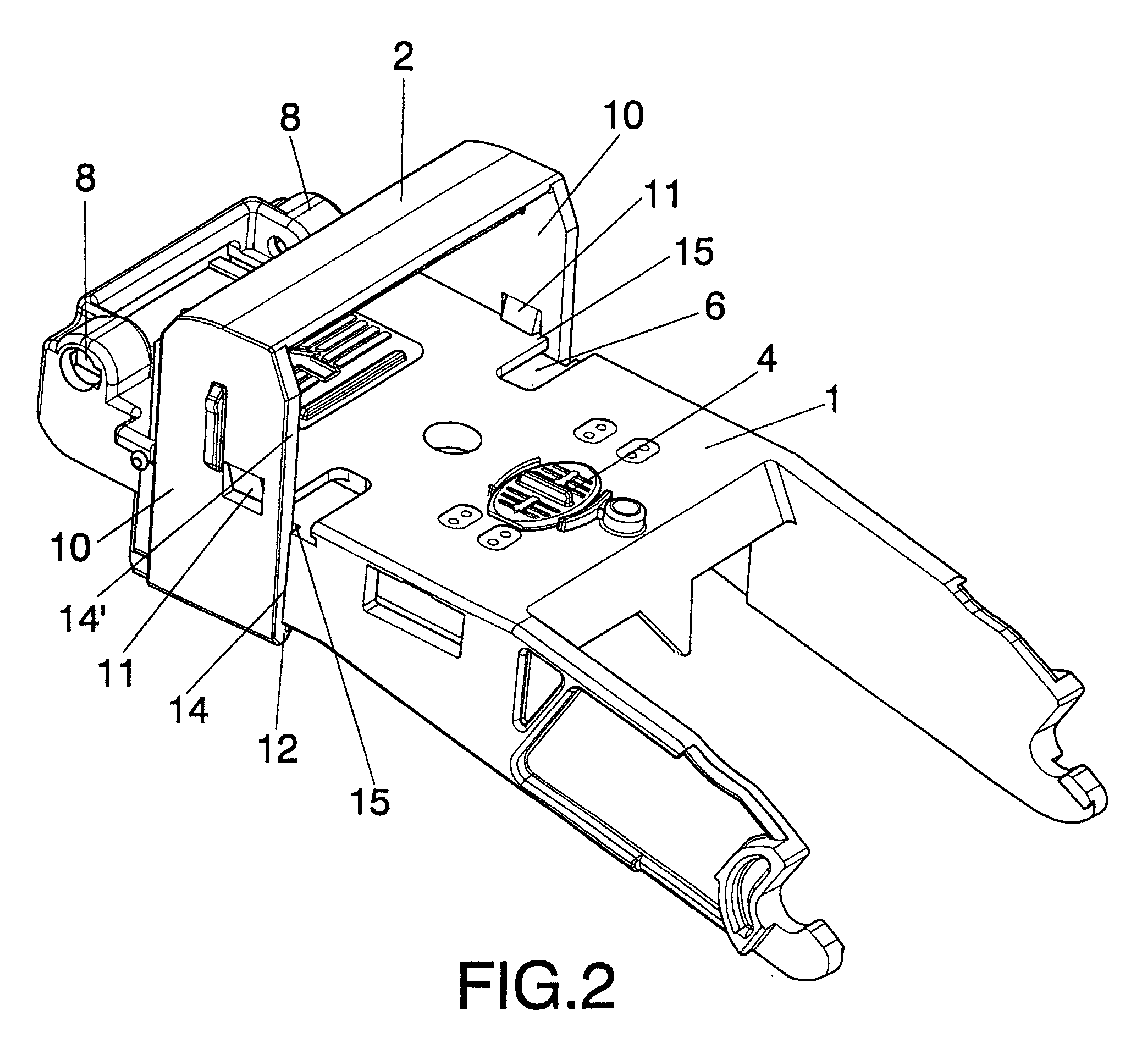
- Figure 2 shows the assembly of the cover arid handle represented in the previous figure.
- Figure 3 shows a view according to an exploded perspective of the cover and the handle in the concealable version.
- Figure 4 shows the assembly corresponding to the cover and handle represented in the previous figure.
- Figure 5 shows a view in perspective of two fuse-holder bases in parallel, which are connected co-laterally forming a single assembly with each other.
- Figure 6 shows a view in transversal cross-section of the two fuse-holder bases, without the fuses, represented in the previous figure, the detail being seen in enlargement of the means which fasten those two bases co-laterally with each other.
- Figure 7 shows a detail in cross-section of the means of securing a fuse with respect to the respective cover of the fuse-holder base.
- Figure 8 shows a representation according to a perspective of the assembly of three fuse-holder bases connected to each other through two side bars with a pair of handles and an intermediate bridge. In this figure the details are seen corresponding to the nipples with cotter of the bars and the complementary cylindrical necks for housing the same foreseen in the covers.
- Figure 9 shows the system of blocking the plug-in bases in the operating position, the blocking being carried out by means of three padlocks.
- Figure 10 also shows a detail in perspective of the means of blocking the fuse-holder bases in the open or non-operating position.
-
- As can be seen in the referenced figures, the fuse-holder base in which the improvements of the invention are applicable, comprises a cover (1) and a handle (2), which can be fixed, the latter pertaining to the actual reference (2), or being a concealable handle, with reference (2'). In any case, the cover (1) constitutes the means of assembly and securing the corresponding fuse (3), the retention and/or release of such fuse (3) being achieved through a piece (4) mounted on the front of the cover (1), capable of lateral displacement so that by its manipulation from the external part of the cover (1) the release and therefore the disassembly of the corresponding fuse (3) can be carried out, as will be explained below.
- That cover (1) has in the corners corresponding to the front part a pair of notches (5), whilst in proximity thereto and in correspondence with the actual front part it includes a pair of rectangular recesses (6), in transversal direction and open toward the sides, the latter having corresponding side rebates (7), which include a channel (7') in correspondence with one of the edges that limit each rebate (7). The cover (1) also has some cylindrical necks (8) the function of which will be explained below, situated in correspondence with one of the ends of its sides.
- Also, in the recesses (6) foreseen in the front of the cover (1) individual pieces (9) can be held which can slide and the function of which will be explained below.
- For its part, the handle (2) which is mounted in a fixed way on the corresponding cover (1), has a U-shape and is mounted in bridge form on the cover (1), the side arms (10) of said cover (2) each having internal pawls (11), whilst below, that is, in correspondence with the free edges of its side arms (10) they have a fold (12) projected toward the interior and in an oblique way, determining a curved plane which is complementary to an also curved surface edge (13) foreseen in the rear part of the side rebates (7) of the cover (1), all this in such a way that the handle (2) is mounted by sliding its side arms (10) over the sides of the cover (1), specifically in correspondence with the rebates (7) of these, until the internal lower fold (12) surpasses the curved and bevelled edge (13) of such rebates (7), at the same time as the pawls (11) determine a means of interlocking when coming to abut upon the front of the cover (1), that is to say the blocking of the handle (2) is achieved in its assembly on the cover (1), such as is represented clearly in figure 2.
- Also, in the channels (7') corresponding to the rebates (7) respective flanges (14) are housed foreseen on one of the edges of the sides (10) of the handle (2), and which flanges (14) have a step (15) from which a flange (14') of greater width is determined, all this in a way such that the interlocking and securing of the handle (2) on the cover (1) is determined by the blocking which is carried out partly by the pawls (11), partly by the guidance of the flanges (14) in the channels (7'), as well as the butt which is formed by the step (15) of those flanges (14-14') and, of course, the hooking action which is implemented by the lower folded edge (12) of the side webs (10) of the aforementioned handle (2), all this as is seen clearly in figure 2, wherein the pawls (11) are engaged in the notches (5) of the actual cover (1).
- The spherical surfaces which determine the edge corresponding to the internal and oblique fold (12) of the side webs (10) of the handle (2), as well as the also spherical surface edge (13) of the rebates (7) of the cover (1), when the handle (2) reaches its assembled position, result in that it can rotate slightly with respect to the cover (1), so that the flange (14) is inserted in the channel (7') of the rebate (7) corresponding to the cover (1), whilst the step (15) determined between the flanges (14) and (14'), rests on the front face of the actual cover (1), all this so that in the moment in which a small rotation is made of the handle (2) once mounted on the cover (1), the aforementioned spherical surfaces corresponding to the handle of the cover will be in perfect mutual support, causing the handle (2) to be slightly inclined and completely blocked in its assembled position, withstanding thereby the large forces which occur in short-circuit disconnection.
- In a variant of embodiment, the handle (2') can be mounted on the corresponding cover (1) in a concealable way, in which case said handle (2') has the already mentioned side webs (10), with the edge turned toward the interior (12), being in this case without the blocking pawls (5), having likewise the flanges (14), the step (15) and the flanges (14'), of greater width than the previous ones. In this case the side webs (10) of the handle (2') have at an approximately intermediate height a pair of notches (16), and another pair of notches in ramp form (17), all this so that in the operating position for said concealable handle (2'), the edge folded toward the interior (12) is locked on the spherical edge (13) of the cover (1), whilst in the side notches (16) the external edges are locked corresponding to the pieces (9) located in the recesses (6) of the cover (1), those pieces (9) having an elastic and internal element by way of a spring which constantly pushes outward in its position on the corresponding recess (6), allowing the lodging of the external edge of the pieces (9) in the aforementioned notches (16), to achieve in this way the blocking of the handle (2') in the operating position.
- Now, if the pieces (9) are pulled toward the interior against the internal elastic element, a transversal displacement of such pieces (9) will take place in the same direction, causing the edge thereof to be released with respect to the notches (16), which allows the displacement of the handle (2') to be carried out against the cover (1), as far as the position of concealment in which the external edge of the pieces (9) is located over the notches (17) in ramp form, said handle (2') being in this way blocked in the non-operating position of concealment, with the particularity that the ramp corresponding to those notches (17), makes possible the pulling of the handle (2') and unfolding thereof until it occupies the aforementioned operating position which is that which is represented specifically in figure 4, with no requirement to act on the piece (9).
- The assembly in parallel of two fuses, as is represented in figure 5, sometimes requires the opening of both in a simultaneous way, for which reason the corresponding covers (1) carrying the fuses (3) are joined co-laterally to each other by means of a pair of pins (18) passing through respective holes (19) foreseen in a facing manner in the two lateral and contiguous webs (10) of the handles (2) corresponding to the two covers (1), as is represented in figure 5, so that on the ends of those pins are threaded corresponding nuts (20), being on the opposing faces of the webs (10) of said handles (2), with the particularity that between those side and contiguous webs (10) are mounted respective spacers (21) constituted by individual sleeves, as is represented clearly in figures 5 and 6 and in the detail of the latter.
- As for the form of securing and holding fixed the fuse (3) on the corresponding cover (1), through the piece (4) already mentioned, this is achieved by virtue of that piece (4) having a leg (22) projected perpendicularly toward the interior which is bent and forms a flexible web (23), so that a rigid and metallic lug (24) pertaining to the actual fuse (3) is introduced in a recess (25) foreseen in the internal part of the front of the cover (1), wherein in turn the leg (22) is positioned with its elastic fluke (23), that lug (24) being narrowed to allow the insertion, through a neck, in the lodging (25), so that in the insertion of such lug (24) in the lodging (25) lateral pressure is applied on the leg (22), which yields due to the elastic fluke (23) thereof, the surpassing of such lug (24) taking place with respect to the leg (22), whereby in that moment the latter constitutes a means of retention which impedes the egress of the lug (24) with respect to the lodging (25) and therefore the release of the fuse (3), which can be disassembled or extracted when the piece (4) is displaced transversally against the elasticity of the fluke (23), which displacement involves the removal of the leg (22) outside the field of mobility of the lug (24) which allows the translation of the latter with the fuse (3) and therefore the extraction of the latter with respect to the cover (1), this detail of assembly and securing of the fuse (3) being represented in figure 7, which as can be verified allows the operation to be carried out in a quick and easy manner.
- The fuse-holder base described can be foreseen for the individual disconnection of each of the phases which intervene in an assembly, wherein logically there are three fuse-holder bases, or they can be foreseen for the simultaneous disconnection of the three phases, or what is the same thing the opening of the three fuses in a simultaneous way, so that for this last case it has been foreseen that the three bases (1), as is represented in figure 8, are mounted in a pivoting way on a pair of side bars (26) defining a common framework for the three covers (1), each one being able to pivot independently of the others or in a simultaneous way, those covers being mounted for the lodging in their cylindrical necks (8) of respective nipples (27), with a cotter (28), foreseen for this purpose in the actual bars (26), so that the nipples (27) with their cotters (28) are complementary to the holes (8) allowing the assembly of each of the covers (1) between the bars (26) with the possibility of the former pivoting, but the detachment thereof from between the bars (26) being impossible, which bars are joined to each other by means of a pair of bridges (28) determining corresponding handles the manual gripping or manipulation of which allows the turning of the bars (26) to be carried out with respect to the covers (1) in order to produce the opening of the latter, the movement being however limited due to the actual movement of the covers (1), in such a way that the cotters (28) of the bars (26) cannot face the keyways of the cylindrical necks (8) and therefore the bars (26) cannot leave their coupling with respect to the covers (1).
- The aforementioned three-phase solution is supplemented with some means which allow blocking both in open position and in closed position, for which it has been foreseen that the intermediate cover (1) has a handle (30) of analogous characteristics to the handles (2) and (2') already mentioned, with the particularity that said handle (30) is concealable but provided on its front with three lugs (31), in which can be introduced a like number of padlocks (32) which allow up to three different operatives to be able to work in the tripolar base and to guarantee that until each one has not removed his padlock the tripolar base cannot change its operating position accidentally.
- Also, between the bars (26) a transversal plate (33) has also been foreseen in the intermediate area, said plate being provided with some transversal ribs (34) with holes (35) which face the holes foreseen in the lugs (31) of the concealable handle (30), so that the padlocks (32) can pass through those holes and through those of the lugs, immobilizing the bars (26) with respect to the covers (1), impeding the opening of these, as is represented in figure 8 and in the enlarged detail corresponding to figure 9.
- Nevertheless, the open position can also be blocked or immobilized, for which when the framework which forms the bars (26) is pulled, making the covers (1) pivot and therefore performing the opening or disconnection, it will suffice that the handle (30) which in the previous position was concealed, be extracted, resulting in that the lugs (31) are introduced in the openings (36) established for this purpose in the plate (33), in order to carry out the hooking of the padlocks (32), as is represented in figure 10, the handle (30) remaining without its concealment being possible and therefore maintaining the open position of the covers (1).
Claims (7)
- Improvements in fuse-holder bases, which being foreseen for their application in those bases constituted from one or several covers on each one of which is mounted in an independent manner the corresponding fuse, which covers are supplemented with a U-shaped handle, the side arms (10) of which are press-fitted on some rebates (7) foreseen in the sides of the cover, said handle allowing the manipulation of the respective cover and performing the disconnection and connection of the base with respect to the conductor bars duly connected to a socket associated with the casing in which the fuse-holder bases are mounted, it being possible for these to be operated in an individual manner establishing single-phase opening or in a simultaneous way establishing three-phase opening, characterised in that each one of the covers (1) has means of retention which allow the assembly and fastening indistinctly of a fixed handle (2), a concealable handle (2') or even of a tripolar disconnection system, as well as means of blocking for the assembly, securing and release of the fuse from the exterior of the cover (1), the said side arms (10) of the handle (2-2') being provided on their free edge with a fold (12) determining an oblique rim toward the interior which presents a spherical surface for resting on a bevelled edge and also with spherical surface (13) foreseen in the lower rear part of the rebates (7) of the cover (1), in such a way that the support of the edge (12) of the handle (2-2') on the spherical surface (13) allows a slight leverage of the handle (2-2') to be carried out with respect to the cover (1) which causes a flange (14) foreseen on one of the edges of the side arms (10) of the handle (2-2') to be housed inside a channel (7') established in one of the internal edges which define the rebates (7) of the cover (1).
- Improvements in fuse-holder bases, according to claim 1, characterised in that the fixed handle (2) has on its side arms (10) some internal pawls (11) which abut against and are lodged in some notches (5) foreseen on the front surface of the cover (1), in correspondence with the corners which the side rebates (7) thereof form, so that the anchorage between said pawls (11) and the notches (5), in combination with the edge folded toward the interior (12) of the side webs (10) and the flanges (14) housed in the channels (7') of the rebates (7) of the sides of the cover (1) due to the leverage of the handle through the effect of the spherical surfaces (12) (13), maintain said cover (2) blocked and immobilized in the operating position.
- Improvements in fuse-holder bases, according to claim 1, characterised in that the concealable handle (2') is mounted in sliding fashion on the rebate (7) of the cover (1), it being able to occupy an operating position and a concealed position, said handle (2') having, as well as the edge folded toward the interior (12) and the flanges (14), some intermediate notches (16) and other notches in ramp form (17) foreseen in proximity to the transversal arm of the handle (2') itself, whilst the cover (1) incorporates some blocking sliding pieces (9), mounted in recesses (6) foreseen on the front part of the cover (1), which have some elastic and internal elements that tend to push the actual pieces (9) outward to maintain their external edge lodged in the notches (16) corresponding to the side webs (10) of the handle (2'), whilst a manual retraction toward the interior of the pieces (9) and corresponding release of their edges with respect to the notches (16), facilitates the displacement toward the concealment of the handle (2'), by displacement on the rebates (7) of the sides of the cover (1), until the external edges of the sliding pieces (9) reach the inclined notches (17), which establish the position of concealment but which permit passing again to the unfolded position of the handle, without acting on the sliding pieces (9), by simply pulling the handle (2') upward since the ramps (17) will cause automatically the displacement of the blocking sliding pieces (9).
- Improvements in fuse-holder bases, according to previous claims, characterised in that the side arms (10) of the handles (2-2') can have pairs of holes (19) through which the mutual linking is facilitated of a pair of covers (1) and therefore the assembly in parallel of two fuses (3), which holes (19) face each other for the positioning of corresponding pins (18) on the ends of which are fastened respective nuts (20) which fasten the side and contiguous arms (10) of the handles (2-2') to each other, the respective covers (1) being fastened in parallel, said means of fastening being supplemented with respective spacing sleeves (21) mounted on the actual pins (18), between the two contiguous webs (10) of the handles (2-2').
- Improvements in fuse-holder bases, according to previous claims, characterised in that the means of blocking (4) the fuse are constituted by a spring-piece mounted in sliding fashion on the front part of the cover (1), to permit the assembly, blocking and release of the corresponding fuse (3), provided internally with a leg (22) which is bent determining an oblique and elastic fluke (23) which facilitates the introduction of a lug (24) belonging to the fuse (3), in a housing (25) corresponding to the internal part of the cover (1), said lug (24) being immobilized on the inside of the housing (25) by means of the leg (22), when the position has been recovered after the passage of said lug (24), impeding the disassembly of the fuse (3); it having been foreseen that a transversal displacement of the piece (4) allows, by displacement of the leg (22) the release of the lug (24) and with it the displacement and disassembly of the fuse (3).
- Improvements in fuse-holder bases, according to claim 1, characterised in that the covers (1) corresponding to the three phases are mounted in a pivoting manner between a pair of side bars (26) serving as a framework, which facilitate the simultaneous operation of said three covers (1) and therefore the opening and closing at the same time thereof; it having been foreseen that said side bars (26) are joined to each other by means of a pair of handles (29); with the particularity that on one of the end parts of the covers (1) some necks (8) have been foreseen in which are lodged nipples (27) with cotter (28) pertaining to the actual side bars (26), a pivoting assembly of the covers (1) being determined with respect to the framework which the side bars (26) form with their transversal handles (29).
- Improvements in fuse-holder bases, according to claim 6, characterised in that the intermediate cover (1) of the three mounted on the pair of side bars (26), has a concealable handle (30) provided with lugs (31) with holes through which are passed the hooks of corresponding padlocks (22), which in turn are made to pass through holes (35) foreseen for this purpose in transversal ribs (34) of a plate (36) foreseen transversally between the side bars (26), determining the means of blocking of the assembly of covers (1) in their closed or connected position; it having been foreseen that in the open position and by extraction of the handle (30) from its concealed position to its operating position, the lugs (31) of said handle (30) are housed in openings (36) foreseen in the transversal plate (33), allowing the passage of the padlock through the holes of those lugs (31) and corresponding blocking of the covers (1) in their open position.
Applications Claiming Priority (1)
| Application Number | Priority Date | Filing Date | Title |
|---|---|---|---|
| PCT/ES2001/000170 WO2002089164A1 (en) | 2001-04-30 | 2001-04-30 | Improvements made to fuse-holder bases |
Publications (2)
| Publication Number | Publication Date |
|---|---|
| EP1306867A1 true EP1306867A1 (en) | 2003-05-02 |
| EP1306867B1 EP1306867B1 (en) | 2008-06-04 |
Family
ID=8244326
Family Applications (1)
| Application Number | Title | Priority Date | Filing Date |
|---|---|---|---|
| EP01931701A Expired - Lifetime EP1306867B1 (en) | 2001-04-30 | 2001-04-30 | Improvements made to fuse-holder bases |
Country Status (5)
| Country | Link |
|---|---|
| EP (1) | EP1306867B1 (en) |
| AT (1) | ATE397784T1 (en) |
| DE (1) | DE60134322D1 (en) |
| ES (1) | ES2307615T3 (en) |
| WO (1) | WO2002089164A1 (en) |
Cited By (6)
| Publication number | Priority date | Publication date | Assignee | Title |
|---|---|---|---|---|
| DE102005007225A1 (en) * | 2005-02-15 | 2006-08-17 | Siemens Ag | Cover for safety load-break switch has adjustable handle which is adjustable between two latched positions whereby handle has two limbs which are guided to movement between latched positions in captive nut |
| EP1775745A1 (en) * | 2005-10-11 | 2007-04-18 | Pronutec, S.A. | Fuse holder with external fuse release |
| EP2031621A2 (en) | 2007-08-27 | 2009-03-04 | Apator S.A. | Low voltage block safety breaker switch with window |
| EP2849191A1 (en) * | 2013-09-11 | 2015-03-18 | Apator S.A. | Security disconnecter with access port in a cover unit |
| EP2860746A1 (en) * | 2013-10-10 | 2015-04-15 | Jean Müller GmbH Elektrotechnische Fabrik | Assembly of two lids of circuit breakers |
| DE102019116721A1 (en) | 2018-06-22 | 2019-12-24 | Hager-Electro SAS (Société par Actions Simplifiee) | Mobile device for a fuse holder and associated fuse holder |
Families Citing this family (3)
| Publication number | Priority date | Publication date | Assignee | Title |
|---|---|---|---|---|
| CA2892220C (en) * | 2014-06-30 | 2021-01-26 | Matthew Rain Darr | Pluggable touch-safe fuse module with built-in removal handle |
| EP3070730B1 (en) | 2015-03-20 | 2017-11-01 | Pronutec, S.A.U. | Fuse holder base |
| CN113948353B (en) * | 2020-07-17 | 2026-04-21 | 温州圣峻电气有限公司 | A pull-out fuse |
Family Cites Families (5)
| Publication number | Priority date | Publication date | Assignee | Title |
|---|---|---|---|---|
| DE4111157A1 (en) * | 1991-04-06 | 1992-10-08 | Mueller Jean Ohg Elektrotech | NH fuse-switch disconnectors in a modular design |
| DE4435828C1 (en) * | 1994-10-07 | 1996-04-25 | Woehner Alfred Gmbh | Switchable-type multipole fuse block for bus=bar systems |
| ES1030945Y (en) * | 1995-04-28 | 1996-04-01 | Ind De Aparellaje Electrico S | WATERTIGHT FUSE BASE. |
| DE19917403A1 (en) * | 1999-04-16 | 2000-10-19 | Mueller Jean Ohg Elektrotech | Fuse switch-disconnector in strip design for NH fuses |
| ES1045626Y (en) * | 2000-03-15 | 2001-03-16 | Crady Electrica S A | IMPROVED TRIPOLAR FUSE HOLDER DISTRIBUTOR. |
-
2001
- 2001-04-30 DE DE60134322T patent/DE60134322D1/en not_active Expired - Fee Related
- 2001-04-30 WO PCT/ES2001/000170 patent/WO2002089164A1/en not_active Ceased
- 2001-04-30 EP EP01931701A patent/EP1306867B1/en not_active Expired - Lifetime
- 2001-04-30 ES ES01931701T patent/ES2307615T3/en not_active Expired - Lifetime
- 2001-04-30 AT AT01931701T patent/ATE397784T1/en not_active IP Right Cessation
Non-Patent Citations (1)
| Title |
|---|
| See references of WO02089164A1 * |
Cited By (8)
| Publication number | Priority date | Publication date | Assignee | Title |
|---|---|---|---|---|
| DE102005007225A1 (en) * | 2005-02-15 | 2006-08-17 | Siemens Ag | Cover for safety load-break switch has adjustable handle which is adjustable between two latched positions whereby handle has two limbs which are guided to movement between latched positions in captive nut |
| DE102005007225B4 (en) * | 2005-02-15 | 2013-11-21 | Siemens Aktiengesellschaft | Cover for fuse switch disconnector with adjustable handle |
| EP1775745A1 (en) * | 2005-10-11 | 2007-04-18 | Pronutec, S.A. | Fuse holder with external fuse release |
| EP2031621A2 (en) | 2007-08-27 | 2009-03-04 | Apator S.A. | Low voltage block safety breaker switch with window |
| EP2849191A1 (en) * | 2013-09-11 | 2015-03-18 | Apator S.A. | Security disconnecter with access port in a cover unit |
| EP2860746A1 (en) * | 2013-10-10 | 2015-04-15 | Jean Müller GmbH Elektrotechnische Fabrik | Assembly of two lids of circuit breakers |
| DE102019116721A1 (en) | 2018-06-22 | 2019-12-24 | Hager-Electro SAS (Société par Actions Simplifiee) | Mobile device for a fuse holder and associated fuse holder |
| DE102019116721B4 (en) | 2018-06-22 | 2024-05-29 | Hager-Electro SAS (Société par Actions Simplifiee) | Mobile device for a fuse holder, fuse holder and electrical control cabinet |
Also Published As
| Publication number | Publication date |
|---|---|
| ATE397784T1 (en) | 2008-06-15 |
| EP1306867B1 (en) | 2008-06-04 |
| DE60134322D1 (en) | 2008-07-17 |
| ES2307615T3 (en) | 2008-12-01 |
| WO2002089164A1 (en) | 2002-11-07 |
Similar Documents
| Publication | Publication Date | Title |
|---|---|---|
| EP1306867B1 (en) | Improvements made to fuse-holder bases | |
| US5577599A (en) | Switch lockouts | |
| EP2149938B1 (en) | Lever type connector | |
| ES2322204T3 (en) | MODULAR MALE PLUG WITH SLIDING INTERLOCK ELEMENT. | |
| US8604367B2 (en) | Circuit breaker with improved lock-off accessory | |
| US10971319B2 (en) | Snap fit circuit breaker and load center system | |
| CA2369861C (en) | A closure casing | |
| EP0717425B1 (en) | A differential protection module with a multipole switch block with a safety coupling for coupling to the multipole switch block | |
| JP4037495B2 (en) | Folding buckle clasp | |
| US20180061606A1 (en) | Pluggable touch-safe fuse module with built-in removal handle | |
| US7152443B2 (en) | Lockable case | |
| ES2198016T3 (en) | APPARATUS AND EXTRACTION SYSTEM OF A CIRCUITAL CIRCUIT. | |
| US9297181B2 (en) | Arc proof door assembly | |
| PL180656B1 (en) | Modular electric connecting assembly | |
| FR2706687A1 (en) | Electrical connector housing element. | |
| US3088004A (en) | Electrical switches | |
| EP2031622B1 (en) | Low voltage safety breaker with park function | |
| JP2020126842A (en) | Locking device for locking lever of multi-pole electrical connector housing | |
| PL367049A1 (en) | Electrical connector | |
| US5905236A (en) | Circuit breaker movable actuator blocking and securing apparatus, means and system | |
| US5187838A (en) | Jointed pocket-book type closing device for watch bands, bracelets, jewels and the like | |
| US2168802A (en) | Loose leaf binder | |
| KR101859728B1 (en) | Detachable type multi-fuse | |
| JP2013135536A (en) | Jumper switching device | |
| JP4395022B2 (en) | Circuit breaker |
Legal Events
| Date | Code | Title | Description |
|---|---|---|---|
| PUAI | Public reference made under article 153(3) epc to a published international application that has entered the european phase |
Free format text: ORIGINAL CODE: 0009012 |
|
| 17P | Request for examination filed |
Effective date: 20021220 |
|
| AK | Designated contracting states |
Designated state(s): AT BE CH CY DE DK ES FI FR GB GR IE IT LI LU MC NL PT SE TR |
|
| AX | Request for extension of the european patent |
Extension state: AL LT LV MK RO SI |
|
| 17Q | First examination report despatched |
Effective date: 20070711 |
|
| GRAP | Despatch of communication of intention to grant a patent |
Free format text: ORIGINAL CODE: EPIDOSNIGR1 |
|
| GRAS | Grant fee paid |
Free format text: ORIGINAL CODE: EPIDOSNIGR3 |
|
| GRAA | (expected) grant |
Free format text: ORIGINAL CODE: 0009210 |
|
| AK | Designated contracting states |
Kind code of ref document: B1 Designated state(s): AT BE CH CY DE DK ES FI FR GB GR IE IT LI LU MC NL PT SE TR |
|
| REG | Reference to a national code |
Ref country code: GB Ref legal event code: FG4D |
|
| REG | Reference to a national code |
Ref country code: CH Ref legal event code: EP |
|
| REF | Corresponds to: |
Ref document number: 60134322 Country of ref document: DE Date of ref document: 20080717 Kind code of ref document: P |
|
| REG | Reference to a national code |
Ref country code: CH Ref legal event code: NV Representative=s name: GRIFFES CONSULTING SA |
|
| REG | Reference to a national code |
Ref country code: IE Ref legal event code: FG4D |
|
| PG25 | Lapsed in a contracting state [announced via postgrant information from national office to epo] |
Ref country code: FI Free format text: LAPSE BECAUSE OF FAILURE TO SUBMIT A TRANSLATION OF THE DESCRIPTION OR TO PAY THE FEE WITHIN THE PRESCRIBED TIME-LIMIT Effective date: 20080604 |
|
| PG25 | Lapsed in a contracting state [announced via postgrant information from national office to epo] |
Ref country code: NL Free format text: LAPSE BECAUSE OF FAILURE TO SUBMIT A TRANSLATION OF THE DESCRIPTION OR TO PAY THE FEE WITHIN THE PRESCRIBED TIME-LIMIT Effective date: 20080604 |
|
| NLV1 | Nl: lapsed or annulled due to failure to fulfill the requirements of art. 29p and 29m of the patents act | ||
| REG | Reference to a national code |
Ref country code: ES Ref legal event code: FG2A Ref document number: 2307615 Country of ref document: ES Kind code of ref document: T3 |
|
| PG25 | Lapsed in a contracting state [announced via postgrant information from national office to epo] |
Ref country code: PT Free format text: LAPSE BECAUSE OF FAILURE TO SUBMIT A TRANSLATION OF THE DESCRIPTION OR TO PAY THE FEE WITHIN THE PRESCRIBED TIME-LIMIT Effective date: 20081104 Ref country code: SE Free format text: LAPSE BECAUSE OF FAILURE TO SUBMIT A TRANSLATION OF THE DESCRIPTION OR TO PAY THE FEE WITHIN THE PRESCRIBED TIME-LIMIT Effective date: 20080904 |
|
| PG25 | Lapsed in a contracting state [announced via postgrant information from national office to epo] |
Ref country code: BE Free format text: LAPSE BECAUSE OF FAILURE TO SUBMIT A TRANSLATION OF THE DESCRIPTION OR TO PAY THE FEE WITHIN THE PRESCRIBED TIME-LIMIT Effective date: 20080604 |
|
| PLBE | No opposition filed within time limit |
Free format text: ORIGINAL CODE: 0009261 |
|
| STAA | Information on the status of an ep patent application or granted ep patent |
Free format text: STATUS: NO OPPOSITION FILED WITHIN TIME LIMIT |
|
| PG25 | Lapsed in a contracting state [announced via postgrant information from national office to epo] |
Ref country code: DK Free format text: LAPSE BECAUSE OF FAILURE TO SUBMIT A TRANSLATION OF THE DESCRIPTION OR TO PAY THE FEE WITHIN THE PRESCRIBED TIME-LIMIT Effective date: 20080604 |
|
| 26N | No opposition filed |
Effective date: 20090305 |
|
| PGFP | Annual fee paid to national office [announced via postgrant information from national office to epo] |
Ref country code: ES Payment date: 20090416 Year of fee payment: 9 |
|
| PG25 | Lapsed in a contracting state [announced via postgrant information from national office to epo] |
Ref country code: IT Free format text: LAPSE BECAUSE OF FAILURE TO SUBMIT A TRANSLATION OF THE DESCRIPTION OR TO PAY THE FEE WITHIN THE PRESCRIBED TIME-LIMIT Effective date: 20080604 |
|
| REG | Reference to a national code |
Ref country code: CH Ref legal event code: PL |
|
| GBPC | Gb: european patent ceased through non-payment of renewal fee |
Effective date: 20090430 |
|
| REG | Reference to a national code |
Ref country code: FR Ref legal event code: ST Effective date: 20091231 |
|
| PG25 | Lapsed in a contracting state [announced via postgrant information from national office to epo] |
Ref country code: CH Free format text: LAPSE BECAUSE OF NON-PAYMENT OF DUE FEES Effective date: 20090430 Ref country code: LI Free format text: LAPSE BECAUSE OF NON-PAYMENT OF DUE FEES Effective date: 20090430 |
|
| PGFP | Annual fee paid to national office [announced via postgrant information from national office to epo] |
Ref country code: DE Payment date: 20091019 Year of fee payment: 9 |
|
| REG | Reference to a national code |
Ref country code: IE Ref legal event code: MM4A |
|
| PG25 | Lapsed in a contracting state [announced via postgrant information from national office to epo] |
Ref country code: MC Free format text: LAPSE BECAUSE OF NON-PAYMENT OF DUE FEES Effective date: 20090430 Ref country code: IE Free format text: LAPSE BECAUSE OF NON-PAYMENT OF DUE FEES Effective date: 20090430 Ref country code: GB Free format text: LAPSE BECAUSE OF NON-PAYMENT OF DUE FEES Effective date: 20090430 Ref country code: FR Free format text: LAPSE BECAUSE OF NON-PAYMENT OF DUE FEES Effective date: 20091222 |
|
| PG25 | Lapsed in a contracting state [announced via postgrant information from national office to epo] |
Ref country code: AT Free format text: LAPSE BECAUSE OF NON-PAYMENT OF DUE FEES Effective date: 20090430 |
|
| PG25 | Lapsed in a contracting state [announced via postgrant information from national office to epo] |
Ref country code: GR Free format text: LAPSE BECAUSE OF FAILURE TO SUBMIT A TRANSLATION OF THE DESCRIPTION OR TO PAY THE FEE WITHIN THE PRESCRIBED TIME-LIMIT Effective date: 20080905 |
|
| PG25 | Lapsed in a contracting state [announced via postgrant information from national office to epo] |
Ref country code: DE Free format text: LAPSE BECAUSE OF NON-PAYMENT OF DUE FEES Effective date: 20101103 |
|
| PG25 | Lapsed in a contracting state [announced via postgrant information from national office to epo] |
Ref country code: LU Free format text: LAPSE BECAUSE OF NON-PAYMENT OF DUE FEES Effective date: 20090430 |
|
| REG | Reference to a national code |
Ref country code: ES Ref legal event code: FD2A Effective date: 20110714 |
|
| PG25 | Lapsed in a contracting state [announced via postgrant information from national office to epo] |
Ref country code: ES Free format text: LAPSE BECAUSE OF NON-PAYMENT OF DUE FEES Effective date: 20110704 |
|
| PG25 | Lapsed in a contracting state [announced via postgrant information from national office to epo] |
Ref country code: TR Free format text: LAPSE BECAUSE OF FAILURE TO SUBMIT A TRANSLATION OF THE DESCRIPTION OR TO PAY THE FEE WITHIN THE PRESCRIBED TIME-LIMIT Effective date: 20080604 |
|
| PG25 | Lapsed in a contracting state [announced via postgrant information from national office to epo] |
Ref country code: ES Free format text: LAPSE BECAUSE OF NON-PAYMENT OF DUE FEES Effective date: 20100501 Ref country code: CY Free format text: LAPSE BECAUSE OF FAILURE TO SUBMIT A TRANSLATION OF THE DESCRIPTION OR TO PAY THE FEE WITHIN THE PRESCRIBED TIME-LIMIT Effective date: 20080604 |