EP1309029A2 - Method and apparatus for controlling cooling and detecting abnormality in battery pack system - Google Patents
Method and apparatus for controlling cooling and detecting abnormality in battery pack system Download PDFInfo
- Publication number
- EP1309029A2 EP1309029A2 EP02257704A EP02257704A EP1309029A2 EP 1309029 A2 EP1309029 A2 EP 1309029A2 EP 02257704 A EP02257704 A EP 02257704A EP 02257704 A EP02257704 A EP 02257704A EP 1309029 A2 EP1309029 A2 EP 1309029A2
- Authority
- EP
- European Patent Office
- Prior art keywords
- battery pack
- cooling
- blocks
- block
- threshold
- Prior art date
- Legal status (The legal status is an assumption and is not a legal conclusion. Google has not performed a legal analysis and makes no representation as to the accuracy of the status listed.)
- Granted
Links
Images


Classifications
-
- H—ELECTRICITY
- H01—ELECTRIC ELEMENTS
- H01M—PROCESSES OR MEANS, e.g. BATTERIES, FOR THE DIRECT CONVERSION OF CHEMICAL ENERGY INTO ELECTRICAL ENERGY
- H01M10/00—Secondary cells; Manufacture thereof
- H01M10/42—Methods or arrangements for servicing or maintenance of secondary cells or secondary half-cells
- H01M10/48—Accumulators combined with arrangements for measuring, testing or indicating the condition of cells, e.g. the level or density of the electrolyte
- H01M10/482—Accumulators combined with arrangements for measuring, testing or indicating the condition of cells, e.g. the level or density of the electrolyte for several batteries or cells simultaneously or sequentially
-
- H—ELECTRICITY
- H01—ELECTRIC ELEMENTS
- H01M—PROCESSES OR MEANS, e.g. BATTERIES, FOR THE DIRECT CONVERSION OF CHEMICAL ENERGY INTO ELECTRICAL ENERGY
- H01M10/00—Secondary cells; Manufacture thereof
- H01M10/60—Heating or cooling; Temperature control
- H01M10/61—Types of temperature control
- H01M10/613—Cooling or keeping cold
-
- H—ELECTRICITY
- H01—ELECTRIC ELEMENTS
- H01M—PROCESSES OR MEANS, e.g. BATTERIES, FOR THE DIRECT CONVERSION OF CHEMICAL ENERGY INTO ELECTRICAL ENERGY
- H01M10/00—Secondary cells; Manufacture thereof
- H01M10/60—Heating or cooling; Temperature control
- H01M10/63—Control systems
- H01M10/633—Control systems characterised by algorithms, flow charts, software details or the like
-
- H—ELECTRICITY
- H01—ELECTRIC ELEMENTS
- H01M—PROCESSES OR MEANS, e.g. BATTERIES, FOR THE DIRECT CONVERSION OF CHEMICAL ENERGY INTO ELECTRICAL ENERGY
- H01M10/00—Secondary cells; Manufacture thereof
- H01M10/60—Heating or cooling; Temperature control
- H01M10/65—Means for temperature control structurally associated with the cells
- H01M10/656—Means for temperature control structurally associated with the cells characterised by the type of heat-exchange fluid
- H01M10/6561—Gases
- H01M10/6563—Gases with forced flow, e.g. by blowers
-
- H—ELECTRICITY
- H01—ELECTRIC ELEMENTS
- H01M—PROCESSES OR MEANS, e.g. BATTERIES, FOR THE DIRECT CONVERSION OF CHEMICAL ENERGY INTO ELECTRICAL ENERGY
- H01M10/00—Secondary cells; Manufacture thereof
- H01M10/42—Methods or arrangements for servicing or maintenance of secondary cells or secondary half-cells
- H01M10/44—Methods for charging or discharging
-
- H—ELECTRICITY
- H01—ELECTRIC ELEMENTS
- H01M—PROCESSES OR MEANS, e.g. BATTERIES, FOR THE DIRECT CONVERSION OF CHEMICAL ENERGY INTO ELECTRICAL ENERGY
- H01M2200/00—Safety devices for primary or secondary batteries
- H01M2200/10—Temperature sensitive devices
-
- Y—GENERAL TAGGING OF NEW TECHNOLOGICAL DEVELOPMENTS; GENERAL TAGGING OF CROSS-SECTIONAL TECHNOLOGIES SPANNING OVER SEVERAL SECTIONS OF THE IPC; TECHNICAL SUBJECTS COVERED BY FORMER USPC CROSS-REFERENCE ART COLLECTIONS [XRACs] AND DIGESTS
- Y02—TECHNOLOGIES OR APPLICATIONS FOR MITIGATION OR ADAPTATION AGAINST CLIMATE CHANGE
- Y02E—REDUCTION OF GREENHOUSE GAS [GHG] EMISSIONS, RELATED TO ENERGY GENERATION, TRANSMISSION OR DISTRIBUTION
- Y02E60/00—Enabling technologies; Technologies with a potential or indirect contribution to GHG emissions mitigation
- Y02E60/10—Energy storage using batteries
Definitions
- the present invention relates to a method and an apparatus for controlling cooling and a method and an apparatus for detecting an abnormality in a battery pack system.
- the battery pack system is composed of a plurality of battery pack blocks, each of which is constituted by connecting a plurality of cells in series, that are connected with one another in series, in parallel, or by a combination of serial connection and parallel connection.
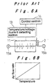
- a conventional battery pack system includes a battery pack block 11 that is composed of a plurality of cells connected in series; a cooling fan 2 for cooling the battery pack block 11; a temperature/voltage/current detecting section 13 for detecting the temperature, voltage, and current of the battery pack block 11 based on output signals of various sensors (not shown) mounted on the battery pack block 11; and a control section 14 for performing various control and alarm functions, including controlling operation of the cooling fan 2 according to the results of detection by the temperature/voltage/current detecting section 13.
- Reference numerals 15a and 15b denote output terminals of the battery pack block 11.
- a battery pack block As an example of a specific configuration of the battery pack block 11, a battery pack block is known in which individual battery modules consist of a serially connected arrangement of, for example, six cells. The battery modules are disposed in parallel with 20 to 30 modules being serially connected. Thereby, an output voltage from one hundred and several tens of volts to several hundred volts can be obtained.
- a battery pack system is considered which consists of an arrangement with a serial or parallel connection, or with a combination of serial and parallel connections, between a plurality of battery pack blocks as described above.
- the respective cooling fans 2 of a plurality of battery pack blocks are controlled by a single cooling mode of operation. Consequently, a variation in the temperatures of the battery pack blocks 11 cannot be avoided, causing a variation in the SOC (State of Charge) of the battery pack blocks 11, and further resulting in various degradation rates. Further, variations in the SOC due to partial replacement of the battery pack blocks 11, also result in differing degradation rates.
- SOC State of Charge
- a method for detecting temperature abnormalities in each battery pack block 11 the difference between an estimated battery temperature and an obtained battery temperature is considered.
- the estimated value is obtained from a heat generation value calculated from charged and discharged capacities derived from current and voltage values, and the cooling capacity of the cooling fan 2.
- the actual temperature value is detected by a sensor.
- An abnormality in the battery pack block 11 is judged when the difference in the estimated and actual detected temperatures exceeds a threshold.
- this method necessitates the provision of a memory for the calculation of estimated temperature. This results in a higher cost and, in addition, tends to cause errors in the estimation value, giving rise to problems in the accuracy of the abnormality detection.
- an object of the present invention is to provide a method and an apparatus for controlling cooling and detecting an abnormality in a battery pack system.
- the method and apparatus increase charging efficiency by restraining variations in the Soc between battery pack blocks, extend the life of the total system by reducing variations in temperature between battery pack blocks and making the degradation rates even, and detect an abnormality in the respective battery pack blocks, all with lowered cost and higher accuracy.
- a method for controlling cooling in a battery pack system the battery pack system being composed of a plurality of battery pack blocks, each of which is constituted by connecting a plurality of cells in series, that are connected with one another in series, in parallel, or by a combination of serial connection and parallel connection.
- the method includes: cooling each battery pack block in an arbitrary cooling mode selected from a plurality of cooling modes for each battery pack block; and controlling the system so that an SOC difference between the respective battery pack blocks is made equal to or smaller than a threshold by switching a cooling mode of a battery pack block when an SOC difference between the battery pack block and another battery pack block exceeds the threshold.
- the battery pack system being composed of a plurality of battery pack blocks, each of which is constituted by connecting a plurality of cells in series, that are connected with one another in series, in parallel, or by a combination of serial connection and parallel connection
- each of the battery pack blocks is provided with an SOC detection unit and a cooling unit
- a control section is installed for controlling respective cooling units by selecting one of a plurality of cooling modes for each cooling unit, and for controlling the cooling unit of a battery pack block by changing a cooling mode thereof, if an SOC difference between the battery pack block and another battery pack block exceeds a threshold.
- a method for controlling cooling in a battery pack system the battery pack system being composed of a plurality of battery pack blocks, each of which is constituted by connecting a plurality of cells in series, that are connected with one another in series, in parallel, or by a combination of serial connection and parallel connection.
- the method includes: cooling each battery pack block in accordance with an arbitrary control map selected from a plurality of control maps for each battery pack block; and controlling the system so that a temperature difference between the respective battery pack blocks is made equal to or smaller than a threshold by changing a control map for use in cooling a battery pack block when a temperature difference between the battery pack block and another battery pack block exceeds the threshold.
- the battery pack system being composed of a plurality of battery pack blocks, each of which is constituted by connecting a plurality of cells in series, that are connected with one another in series, in parallel, or by a combination of serial connection and parallel connection
- each of the battery pack blocks is provided with an SOC detection unit and a cooling unit
- a control section is installed for controlling respective cooling units by selecting one of a plurality of control maps for each cooling unit, and for controlling the cooling unit of a battery pack block by changing a control map thereof, if a temperature difference between the battery pack block and another battery pack block exceeds a threshold.
- control section is preferably configured to detect, as an abnormality, a temperature difference between battery pack blocks exceeding the threshold even with cooling according to a control map with a highest cooling capacity.
- the SOC differences between the respective battery pack blocks are preferentially controlled by the method for controlling cooling in a battery pack system according to the first aspect of the invention described above so that the SOC difference is made equal to or smaller than a threshold, and then a temperature difference between the respective battery pack blocks is controlled by the method for controlling cooling in a battery pack system according to the second aspect of the invention described above so that the temperature difference is made equal to or smaller than a threshold.
- a method for detecting an abnormality in a battery pack system the battery pack system being composed of a plurality of battery pack blocks, each of which is constituted by connecting a plurality of cells in series, that are connected with one another in series, in parallel, or by a combination of serial connection and parallel connection.
- the method includes: detecting, as an abnormality, a temperature difference between one battery pack block and another battery pack block exceeding a threshold.
- the battery pack system being composed of a plurality of battery pack blocks, each of which is constituted by connecting a plurality of cells in series, that are connected with one another in series, in parallel, or by a combination of serial connection and parallel connection
- each of the battery pack blocks is provided with a temperature detection unit and a cooling unit
- an abnormality detection part is installed for detecting, as an abnormality, a temperature difference between one battery pack block and another battery pack block exceeding a threshold.
- a control map for cooling the one battery pack block is changed in cooling, and when the temperature difference between the one battery pack block and the other battery pack block exceeds the threshold even with cooling according to a control map with a highest cooling capability, an abnormality is detected.
- a battery pack system 10 includes four battery pack blocks 1a to 1d, each of which is constituted by connecting a plurality of cells in series.
- the battery pack blocks 1a and 1c, as well as 1b and 1d, are connected in series, thereby constituting two battery pack block groups. These battery pack block groups are connected in parallel, whereupon the battery pack system 10 is realized.
- the battery pack blocks 1a to 1d are each constructed as follows. For example, six cells are connected together in series so as to provide a battery module, and 20 to 30 units of such battery modules are disposed in parallel and connected in series.
- the battery pack blocks 1a to 1d are provided with cooling fans 2a to 2d as a cooling unit, respectively, for cooling purposes.
- each of the battery pack blocks 1a to 1d there are temperature/voltage/current detecting sections 3a to 3d. These are provided to detect temperatures, voltages, and currents of the battery pack blocks 1a to 1d based on the output signals of various sensors (not shown) respectively mounted thereon. The results of the detection by the respective temperature/voltage/current detecting sections 3a to 3d are inputted to a control section 4 which carries out various control and alarm functions for each of the battery pack blocks 1a to 1d. This is according to the results of the detection and, in addition, control extends to operational control of the cooling fans 2a to 2d.
- Reference numerals 5a and 5b denote output terminals of the battery pack system 10.
- the control section 4 calculates the SOC of each of the battery pack blocks 1a to 1d from an input voltage, a current value, and the like, and then calculates differences in the capacity between the battery pack blocks.
- the control section 4 also computes differences in temperatures between the battery pack blocks 1a to 1d, based on the input temperatures thereof.
- mode 1 and mode 2 are set as cooling modes.
- the mode 1 represents a normal state and the mode 2 represents a case where there is a variation in capacity.
- the control section 4 is set such that the control section 4 is able to greatly change the air flow rate when in mode 1. This change ranges from a high flow rate to a low flow rate according to temperatures of the battery pack blocks. In contrast, when in mode 2, the control section 4 changes the air flow rate by a lesser degree. This ranges from a medium flow rate to a low flow rate according to temperatures of the battery pack blocks.
- MAP 1 to MAP 4 are set so as to specify changes in the air flow rate according to temperature. Firstly, MAP 1, which is for the first stage with the lowest air flow rate (representing a low cooling capacity) is selected. This is then changed to MAPS 2 through 4 for the second through fourth stages with increasingly greater air flow rates. Actual air flow rate data output from the control section 4 to control the cooling fans 2a to 2d is determined as a product of the cooling modes (1 or 2) and MAPs 1 to 4.
- step #1 it is judged whether each capacity (SOC) difference between respective battery pack blocks 1a to 1d is equal to or greater than a predetermined threshold 'A'. If the difference is smaller than the threshold 'A', the process proceeds to step #3, which sets the cooling mode to mode 1. If the difference is equal to or greater than the threshold 'A', it is then judged in step #2 whether the battery temperature is lower than 'T' degrees C (e.g. 50 degrees C). The temperature 'T' has been set as a temperature value wherein temperatures equal to or higher than 'T' are not preferable. If the battery temperature is equal to or higher than 'T' degrees C, the process proceeds to step #3 and sets the cooling mode to mode 1. If the battery temperature is lower than 'T' degrees C, the process proceeds to step #4 and sets the cooling mode to mode 2.
- SOC capacity
- step #5 it is judged whether the temperature difference of each battery pack block when compared with the temperature of the battery pack block having the lowest temperature is equal to or greater than a predetermined threshold 't' degrees C. If the temperature difference is smaller than the threshold of 't' degrees C, the process proceeds to step #6 to continue operational control of the cooling fans 2a to 2d without changing the MAP. On the other hand, if the temperature difference is equal to or greater than the threshold of 't' degrees C, then the number of the MAP currently used is checked. If the MAP number is 4, which is the number of the MAP with the highest air flow rate, the process proceeds to step #9 to perform an abnormality notification.
- the process proceeds to the step #8 to change the control MAP to a MAP with an air flow rate one level higher. It then continues cooling operation by the cooling fans 2a to 2d.
- any abnormality is notified when the temperature difference between any battery pack block and another exceeds a threshold, it is only necessary to detect the temperature differences between the battery pack blocks 1a to 1d. This eliminates calculation memory and a program for the calculation of estimated temperatures required in the prior art. Further, as estimated values (which tend to give rise to errors) are not used, abnormalities are detected at a lower cost and with a higher accuracy.
- steps #1 to #4 if an SOC difference between battery pack blocks exceeds a predetermined threshold, the cooling mode is changed.
- steps #5 to #8 if a temperature difference, between battery pack blocks exceeds a predetermined threshold, a cooling control MAP is changed. Control operations are accordingly performed at predetermined intervals. To decrease the temperature difference between the battery pack blocks, in order to prioritize even degradation rates and increased life of the total system, control can be carried out such that (as shown in Fig. 5) steps #5 to #8 are repeated until the temperature difference stops exceeding the predetermined threshold.
- control for reducing variations in the soc between battery pack blocks is performed in integration with control for decreasing the temperature difference between battery pack blocks
- the controls may be performed independently. It is also permitted to selectively perform either control depending on usage conditions, usage status, and other various conditions of the battery pack system.
- connection system can employ serial, parallel, or any combination of parallel and serially connected blocks.
- a method and an apparatus for controlling cooling in a battery pack system control the SOC differences between battery pack blocks so that the SOC differences are made equal to or smaller than a threshold, whereby variation in SOC between respective battery pack blocks is restrained to improve charging efficiency.
- the method and the apparatus control the temperature differences between the battery pack blocks so that the temperature differences are made equal to or smaller than a threshold, whereby variation in temperature between the battery pack blocks is reduced, and the degradation rates are made even to extend the life of the total system.
- a method and an apparatus for detecting an abnormality in a battery pack system detect only temperature differences between battery pack blocks to judge an abnormality, whereby an abnormality is detected inexpensively and with a higher accuracy.
Landscapes
- Engineering & Computer Science (AREA)
- Manufacturing & Machinery (AREA)
- Chemical & Material Sciences (AREA)
- Chemical Kinetics & Catalysis (AREA)
- Electrochemistry (AREA)
- General Chemical & Material Sciences (AREA)
- Automation & Control Theory (AREA)
- Secondary Cells (AREA)
- Charge And Discharge Circuits For Batteries Or The Like (AREA)
Abstract
Description
Claims (11)
- A method for controlling cooling in a battery pack system (10), the battery pack system being composed of a plurality of battery pack blocks (1a, 1b, 1c, 1d) connected with one another in series, in parallel, or by a combination of serial connection and parallel connection, each of the battery pack blocks being constituted by connecting a plurality of cells in series, characterized in that the method comprises:cooling each of the battery pack blocks in a cooling mode selected from a plurality of cooling modes for each battery pack block; andcontrolling the system so that an SOC difference between the battery pack blocks is made equal to or smaller than a threshold, when an SOC difference between one battery pack block and another battery pack block exceeds the threshold, by switching a cooling mode of the one battery pack block.
- The method for controlling cooling in a battery pack system (10) according to claim 1, further comprising switching a cooling mode of a battery pack block (1a, 1b, 1c, 1d) with a higher SOC to a cooling mode with a lower cooling capacity under a condition that a battery temperature is not exceeding a predetermined temperature.
- A method for controlling cooling in a battery pack system (10), the battery pack system being composed of a plurality of battery pack blocks (1a, 1b 1c, 1d) connected with one another in series, in parallel, or by a combination of serial connection and parallel connection, each of the battery pack blocks being constituted by connecting a plurality of cells in series, characterized in that the method comprises:cooling each of the battery pack blocks in accordance with a control map selected from a plurality of control maps for each battery pack block; andcontrolling the system so that a temperature difference between the battery pack blocks is made equal to or smaller than a threshold, when a temperature difference between one battery pack block and another battery pack block exceeds the threshold, by changing the control map for use in cooling the one battery pack block.
- The method for controlling cooling in a battery pack system (10) according to claim 3, further comprising changing a control map of a cooling unit (2a, 2b, 2c, 2d) of a battery pack block (1a, 1b, 1c, 1d) with a higher temperature to a control map with a higher cooling capacity.
- A method for controlling cooling in a battery pack system (10), the method comprising:controlling an SOC difference between battery pack blocks (1a, 1b, 1c, 1d) in accordance with the method for controlling cooling in a battery pack system according to claim 1 so as to make the difference equal to or smaller than a threshold; andcontrolling a temperature difference between the battery pack blocks in accordance with the method for controlling cooling in a battery pack system according to claim 3 so as to make the temperature difference equal to or smaller than a threshold.
- A method for detecting an abnormality in a battery pack system (10), the battery pack system being composed of a plurality of battery pack blocks (1a, 1b, 1c, 1d) connected with one another in series, in parallel, or by a combination of serial connection and parallel connection, each of the battery pack blocks being constituted by connecting a plurality of cells in series, characterized in that the method comprises:detecting, as an abnormality, a temperature difference between one battery pack block and another battery pack block exceeding a threshold.
- The method for detecting an abnormality in a battery pack system (10) according to claim 6, wherein, when the temperature difference between the one battery pack block and the other battery pack block exceeds the threshold, a control map for cooling the one battery pack block is changed, and when the temperature difference exceeds the threshold even with a cooling according to a control map with a highest cooling capability, an abnormality is detected.
- An apparatus for controlling cooling in a battery pack system (10), the battery pack system being composed of a plurality of battery pack blocks (1a, 1b, 1c, 1d) connected with one another in series, in parallel, or by a combination of serial connection and parallel connection, each of the battery pack blocks being constituted by connecting a plurality of cells in series, the apparatus comprising a control section (4), wherein each of the battery pack blocks is provided with an SOC detecting unit (3a, 3b, 3c, 3d) and a cooling unit (2a, 2b, 2c, 2d), and the control section controls respective cooling units by selecting one of a plurality of cooling modes for each cooling unit, and, if an SOC difference between one battery pack block and another battery pack block exceeds a threshold, the control section controls the cooling unit of the one battery pack block by changing the cooling mode thereof.
- An apparatus for controlling cooling in a battery pack system (10), the battery pack system being composed of a plurality of battery pack blocks (1a, 1b, 1c, 1d) connected with one another in series, in parallel, or by a combination of serial connection and parallel connection, each of the battery pack blocks being constituted by connecting a plurality of cells in series, the apparatus comprising a control section (4), wherein each of the battery pack blocks is provided with a temperature detecting unit (3a, 3b, 3c, 3d) and a cooling unit (2a, 2b, 2c, 2d), and the control section controls respective cooling units by selecting one of a plurality of control maps for each cooling unit, and, if a temperature difference between one battery pack block and another battery pack block exceeds a threshold, the control section controls the cooling unit of the one battery pack block by changing the control map thereof.
- The apparatus for controlling cooling in a battery pack system (10) according to claim 9, wherein the control section (4) detects, as an abnormality, a temperature difference exceeding the threshold even with cooling according to a control map with a highest cooling capacity.
- An apparatus for detecting an abnormality in a battery pack system (10), the battery pack system being composed of a plurality of battery pack blocks (1a, 1b, 1c, 1d) connected with one another in series, in parallel, or by a combination of serial connection and parallel connection, each of the battery pack blocks being constituted by connecting a plurality of cells in series, the apparatus comprising an abnormality detection section (4), wherein each of the battery pack blocks is provided with a temperature detecting unit (3a, 3b, 3c, 3d) and a cooling unit (2a, 2b, 2c, 2d), and the abnormality detection section detects, as an abnormality, a temperature difference between one battery pack block and another battery pack block exceeding a threshold.
Applications Claiming Priority (2)
| Application Number | Priority Date | Filing Date | Title |
|---|---|---|---|
| JP2001340660A JP4673529B2 (en) | 2001-11-06 | 2001-11-06 | Method and apparatus for controlling assembled battery system |
| JP2001340660 | 2001-11-06 |
Publications (3)
| Publication Number | Publication Date |
|---|---|
| EP1309029A2 true EP1309029A2 (en) | 2003-05-07 |
| EP1309029A3 EP1309029A3 (en) | 2004-03-03 |
| EP1309029B1 EP1309029B1 (en) | 2011-03-02 |
Family
ID=19154819
Family Applications (1)
| Application Number | Title | Priority Date | Filing Date |
|---|---|---|---|
| EP20020257704 Expired - Lifetime EP1309029B1 (en) | 2001-11-06 | 2002-11-06 | Method and apparatus for controlling cooling and detecting abnormality in battery pack system |
Country Status (4)
| Country | Link |
|---|---|
| US (1) | US6903534B2 (en) |
| EP (1) | EP1309029B1 (en) |
| JP (1) | JP4673529B2 (en) |
| DE (1) | DE60239314D1 (en) |
Cited By (9)
| Publication number | Priority date | Publication date | Assignee | Title |
|---|---|---|---|---|
| US7102310B2 (en) | 2004-06-02 | 2006-09-05 | Toyota Jidosha Kabushiki Kaisha | Cooling device of power supply |
| US20110042058A1 (en) * | 2007-03-06 | 2011-02-24 | Toyota Jidosha Kabushiki Kaisha | Cooling apparatus and cooling method for electrical equipment |
| US20130004812A1 (en) * | 2010-03-15 | 2013-01-03 | Mitsubishi Heavy Industries, Ltd. | Battery assembly |
| EP2637248A1 (en) * | 2012-03-09 | 2013-09-11 | Hitachi Ltd. | Battery system and temperature control method therefor |
| EP2448778A4 (en) * | 2009-07-01 | 2013-11-20 | Johnson Controls Saft Advanced | Battery system with improved thermal management system |
| EP2566009A4 (en) * | 2010-04-28 | 2013-12-04 | Toyota Motor Co Ltd | CONTROL DEVICE AND METHOD FOR CONTROLLING THE CHARGE OF A SECONDARY BATTERY |
| DE102013226145A1 (en) | 2013-12-17 | 2015-06-18 | Robert Bosch Gmbh | Device and method for monitoring an energy storage and energy storage device |
| DE102017009131A1 (en) | 2017-09-29 | 2018-03-01 | Daimler Ag | High-voltage battery and method for monitoring a temperature of a battery control device in an active and inactive operating state |
| WO2022029446A1 (en) * | 2020-08-06 | 2022-02-10 | Hyperdrive Innovation Limited | Battery pack |
Families Citing this family (56)
| Publication number | Priority date | Publication date | Assignee | Title |
|---|---|---|---|---|
| JP3939546B2 (en) * | 2001-12-06 | 2007-07-04 | パナソニック・イーブイ・エナジー株式会社 | Battery power device for electric vehicle |
| US20070257642A1 (en) * | 2003-06-19 | 2007-11-08 | Sean Xiao | Battery cell monitoring and balancing circuit |
| JP2005011757A (en) * | 2003-06-20 | 2005-01-13 | Toyota Motor Corp | Secondary battery temperature abnormality detection device and abnormality detection method |
| JP2005160132A (en) * | 2003-11-20 | 2005-06-16 | Toyota Motor Corp | Cooling device abnormality judgment device |
| JP4592312B2 (en) * | 2004-03-24 | 2010-12-01 | 三洋電機株式会社 | Battery pack for vehicles |
| JP4802453B2 (en) * | 2004-04-22 | 2011-10-26 | トヨタ自動車株式会社 | Battery pack, battery pack cooling control method, and computer-readable recording medium storing a program for causing a computer to execute battery pack cooling control |
| JP4513426B2 (en) * | 2004-06-15 | 2010-07-28 | トヨタ自動車株式会社 | Temperature sensor abnormality detection method and power supply device |
| JP4810803B2 (en) * | 2004-07-13 | 2011-11-09 | トヨタ自動車株式会社 | Power supply |
| US20060164795A1 (en) * | 2005-01-21 | 2006-07-27 | International Business Machines Corporation | Systems and methods for thermally isolating independent energy producing entities |
| WO2006108302A1 (en) * | 2005-04-15 | 2006-10-19 | Avestor Limited Partnership | LITHIUM RECHARGEABLE CELL HAVING AN EXCESS OF LiFePO4 BASED CATHODE RELATIVE TO A Li4Ti5O12 BASED ANODE |
| JP4772374B2 (en) * | 2005-04-27 | 2011-09-14 | プライムアースEvエナジー株式会社 | Battery pack device |
| US8816645B2 (en) | 2005-07-20 | 2014-08-26 | Aerovironment, Inc. | Integrated battery unit with cooling and protection expedients for electric vehicles |
| EP1780865B1 (en) * | 2005-10-31 | 2017-02-22 | Black & Decker, Inc. | Thermal management system for a battery pack |
| JP5008863B2 (en) * | 2005-11-30 | 2012-08-22 | プライムアースEvエナジー株式会社 | Secondary battery control device, secondary battery deterioration determination method using secondary battery temperature estimation method |
| JP4640348B2 (en) * | 2007-02-01 | 2011-03-02 | トヨタ自動車株式会社 | Power supply |
| US7671567B2 (en) * | 2007-06-15 | 2010-03-02 | Tesla Motors, Inc. | Multi-mode charging system for an electric vehicle |
| US8049460B2 (en) * | 2007-07-18 | 2011-11-01 | Tesla Motors, Inc. | Voltage dividing vehicle heater system and method |
| US20090123814A1 (en) * | 2007-10-09 | 2009-05-14 | Mason Cabot | Power source and method of managing a power source |
| US7994755B2 (en) | 2008-01-30 | 2011-08-09 | Lg Chem, Ltd. | System, method, and article of manufacture for determining an estimated battery cell module state |
| JP5326503B2 (en) * | 2008-11-05 | 2013-10-30 | 株式会社デンソー | Battery cooling device |
| JP4975715B2 (en) * | 2008-11-20 | 2012-07-11 | 住友重機械工業株式会社 | Charge / discharge control device |
| FR2942080B1 (en) | 2009-02-09 | 2011-04-01 | Vehicules Electr Soc D | METHOD OF THERMALLY MANAGING AN ELECTRIC BATTERY |
| FR2942081B1 (en) * | 2009-02-09 | 2011-03-11 | Soc De Vehicules Electriques | METHOD OF THERMALLY MANAGING AN ELECTRIC BATTERY |
| JP2010257885A (en) * | 2009-04-28 | 2010-11-11 | Toyota Motor Corp | Battery device |
| US20100275619A1 (en) * | 2009-04-30 | 2010-11-04 | Lg Chem, Ltd. | Cooling system for a battery system and a method for cooling the battery system |
| US8154256B2 (en) * | 2009-05-28 | 2012-04-10 | Tesla Motors, Inc. | Battery thermal event detection system using an electrical conductor with a thermally interruptible insulator |
| US8092081B2 (en) * | 2009-05-28 | 2012-01-10 | Tesla Motors, Inc. | Battery thermal event detection system using an optical fiber |
| US8059007B2 (en) * | 2009-05-28 | 2011-11-15 | Tesla Motors, Inc. | Battery thermal event detection system using a thermally interruptible electrical conductor |
| US8449998B2 (en) | 2011-04-25 | 2013-05-28 | Lg Chem, Ltd. | Battery system and method for increasing an operational life of a battery cell |
| EP2800229A4 (en) * | 2011-12-26 | 2015-08-26 | Hitachi Ltd | BATTERY SYSTEM |
| US20130228387A1 (en) * | 2012-01-24 | 2013-09-05 | Ford Global Technologies, Llc | Drive Battery Arrangement and Motor Vehicle Having a Drive Battery Arrangement |
| CN103247828A (en) * | 2012-02-02 | 2013-08-14 | 凹凸电子(武汉)有限公司 | Apparatus and method for processing battery abnormity, battery system and electric equipment |
| US8970173B2 (en) | 2012-02-28 | 2015-03-03 | Tesla Motors, Inc. | Electric vehicle battery lifetime optimization operational mode |
| JP6065339B2 (en) * | 2012-08-13 | 2017-01-25 | 日立工機株式会社 | Back load type power supply |
| JP6151062B2 (en) * | 2013-04-01 | 2017-06-21 | 三菱重工業株式会社 | Power storage system and temperature control method for power storage system |
| JP6299549B2 (en) * | 2014-09-29 | 2018-03-28 | トヨタ自動車株式会社 | Battery cooling system |
| DE112015006567B4 (en) * | 2015-05-27 | 2023-05-25 | Mitsubishi Electric Corporation | energy storage device |
| JP6507951B2 (en) * | 2015-09-07 | 2019-05-08 | 株式会社デンソー | Battery pack |
| JP6722382B2 (en) * | 2015-09-15 | 2020-07-15 | トヨタ自動車株式会社 | Method and apparatus for inspecting assembled battery unit |
| US9979056B2 (en) | 2015-09-22 | 2018-05-22 | Ford Global Technologies, Llc | Battery pack flow control system with fan assembly |
| US9985325B2 (en) | 2015-09-22 | 2018-05-29 | Ford Global Technologies, Llc | Battery pack flow control method |
| DE102016207272A1 (en) * | 2016-04-28 | 2017-11-02 | Bayerische Motoren Werke Aktiengesellschaft | Switchable storage system for a vehicle |
| KR102052241B1 (en) * | 2016-09-21 | 2019-12-04 | 주식회사 엘지화학 | System and method for battery management using Balancing battery |
| KR102286919B1 (en) * | 2017-02-20 | 2021-08-06 | 현대자동차주식회사 | Control method for charging of plug-in vehicle |
| JP6822263B2 (en) * | 2017-03-24 | 2021-01-27 | 株式会社Gsユアサ | Failure diagnostic device |
| CA3181599A1 (en) * | 2017-07-24 | 2019-01-31 | Koki Holdings Co., Ltd. | Battery pack and electrical device using battery pack |
| CN111403857B (en) * | 2019-01-02 | 2022-05-31 | 加百裕工业股份有限公司 | Battery pack temperature equalization system and method |
| MX2021011134A (en) | 2019-03-14 | 2021-12-10 | Generac Power Systems Inc | THERMAL MANAGEMENT OF THE BATTERY MODULE. |
| JP7263873B2 (en) * | 2019-03-25 | 2023-04-25 | Tdk株式会社 | Capacitor module, resonator, wireless power transmitter, wireless power receiver, wireless power transmission system, and module |
| CN110429351B (en) * | 2019-06-17 | 2021-07-20 | 深圳市华宝新能源股份有限公司 | A battery management method and battery management device |
| JP7369274B2 (en) * | 2019-08-01 | 2023-10-25 | エルジー エナジー ソリューション リミテッド | Battery temperature control device, battery system, energy storage system and battery temperature control method |
| JP7137767B2 (en) * | 2019-09-25 | 2022-09-15 | トヨタ自動車株式会社 | Assembled battery ventilation system and vehicle |
| US11588194B2 (en) * | 2020-08-24 | 2023-02-21 | Guangzhou Automobile Group Co., Ltd. | Battery heat adjustment circuit and method, storage medium and electronic device |
| KR102639780B1 (en) * | 2021-10-14 | 2024-02-21 | 엘지전자 주식회사 | Energy Storage System |
| EP4586361A4 (en) * | 2022-10-17 | 2026-03-11 | Lg Energy Solution Ltd | BATTERY PACK WITH HETEROGENIC BATTERY CELLS |
| CN117895128B (en) * | 2023-12-08 | 2025-04-25 | 福建时代星云科技有限公司 | Air-cooled battery system and thermal management method thereof |
Family Cites Families (20)
| Publication number | Priority date | Publication date | Assignee | Title |
|---|---|---|---|---|
| US7728A (en) * | 1850-10-22 | Cheese-press | ||
| US129457A (en) * | 1872-07-16 | Improvement in sole-edge-burnishing machines for boots and shoes | ||
| US87147A (en) * | 1869-02-23 | Improvement in churns | ||
| EP0609101B1 (en) * | 1993-01-29 | 2002-06-26 | Canon Kabushiki Kaisha | Electric power accumulating apparatus and electric power system |
| JP3331529B2 (en) * | 1993-01-29 | 2002-10-07 | キヤノン株式会社 | Power storage device and power system |
| US5670861A (en) * | 1995-01-17 | 1997-09-23 | Norvik Tractions Inc. | Battery energy monitoring circuits |
| JPH09289701A (en) * | 1996-04-19 | 1997-11-04 | Nissan Motor Co Ltd | Output control device for electric vehicles |
| JP3304777B2 (en) * | 1996-08-22 | 2002-07-22 | トヨタ自動車株式会社 | Electric vehicle |
| JPH10201121A (en) * | 1997-01-09 | 1998-07-31 | Sanyo Electric Co Ltd | Apparatus and method for charging of set battery |
| JP3573927B2 (en) * | 1997-08-29 | 2004-10-06 | 三洋電機株式会社 | Battery unit charging method and device |
| JP2000100481A (en) * | 1998-09-18 | 2000-04-07 | Fuji Heavy Ind Ltd | Battery box for electric vehicles |
| JP2001095160A (en) * | 1999-09-17 | 2001-04-06 | Matsushita Electric Ind Co Ltd | Abnormal battery cell detection method |
| JP4049959B2 (en) * | 1999-11-11 | 2008-02-20 | 本田技研工業株式会社 | Battery charging method |
| JP2001196103A (en) | 2000-01-12 | 2001-07-19 | Matsushita Electric Ind Co Ltd | Battery cooling structure |
| US6215281B1 (en) * | 2000-03-16 | 2001-04-10 | General Motors Corporation | Method and apparatus for reducing battery charge time and energy consumption, as in a nickel metal hydride battery pack |
| JP4242998B2 (en) * | 2000-04-03 | 2009-03-25 | 三洋電機株式会社 | Battery temperature equalization control device |
| JP4872143B2 (en) * | 2000-05-01 | 2012-02-08 | トヨタ自動車株式会社 | Cooling device for secondary battery |
| JP3926114B2 (en) * | 2001-04-18 | 2007-06-06 | 株式会社マキタ | Management method of multiple charging devices |
| JP3936169B2 (en) | 2001-11-06 | 2007-06-27 | パナソニック・イーブイ・エナジー株式会社 | Abnormality detection method and apparatus for assembled battery system |
| JP3893291B2 (en) | 2002-01-10 | 2007-03-14 | パナソニック・イーブイ・エナジー株式会社 | Battery power unit for hybrid vehicles |
-
2001
- 2001-11-06 JP JP2001340660A patent/JP4673529B2/en not_active Expired - Lifetime
-
2002
- 2002-11-05 US US10/287,642 patent/US6903534B2/en not_active Expired - Lifetime
- 2002-11-06 EP EP20020257704 patent/EP1309029B1/en not_active Expired - Lifetime
- 2002-11-06 DE DE60239314T patent/DE60239314D1/en not_active Expired - Lifetime
Cited By (18)
| Publication number | Priority date | Publication date | Assignee | Title |
|---|---|---|---|---|
| DE102005025142B4 (en) * | 2004-06-02 | 2007-04-19 | Toyota Jidosha Kabushiki Kaisha, Toyota | Cooling device for a power supply |
| CN100414767C (en) * | 2004-06-02 | 2008-08-27 | 丰田自动车株式会社 | power cooling equipment |
| US7102310B2 (en) | 2004-06-02 | 2006-09-05 | Toyota Jidosha Kabushiki Kaisha | Cooling device of power supply |
| US20110042058A1 (en) * | 2007-03-06 | 2011-02-24 | Toyota Jidosha Kabushiki Kaisha | Cooling apparatus and cooling method for electrical equipment |
| US8733430B2 (en) * | 2007-03-06 | 2014-05-27 | Toyota Jidosha Kabushiki Kaisha | Cooling apparatus and cooling method for electrical equipment |
| EP2448778A4 (en) * | 2009-07-01 | 2013-11-20 | Johnson Controls Saft Advanced | Battery system with improved thermal management system |
| US20130004812A1 (en) * | 2010-03-15 | 2013-01-03 | Mitsubishi Heavy Industries, Ltd. | Battery assembly |
| EP2549582A4 (en) * | 2010-03-15 | 2014-05-28 | Mitsubishi Heavy Ind Ltd | Battery assembly |
| EP2566009A4 (en) * | 2010-04-28 | 2013-12-04 | Toyota Motor Co Ltd | CONTROL DEVICE AND METHOD FOR CONTROLLING THE CHARGE OF A SECONDARY BATTERY |
| US9059595B2 (en) | 2010-04-28 | 2015-06-16 | Toyota Jidosha Kabushiki Kaisha | Charging control method for secondary battery and control device |
| EP2637248A1 (en) * | 2012-03-09 | 2013-09-11 | Hitachi Ltd. | Battery system and temperature control method therefor |
| DE102013226145A1 (en) | 2013-12-17 | 2015-06-18 | Robert Bosch Gmbh | Device and method for monitoring an energy storage and energy storage device |
| WO2015090915A1 (en) | 2013-12-17 | 2015-06-25 | Robert Bosch Gmbh | Device and method for monitoring an energy store and energy store having the device |
| CN105830275A (en) * | 2013-12-17 | 2016-08-03 | 罗伯特·博世有限公司 | Device and method for monitoring an energy store and energy store with the device |
| US20160315363A1 (en) * | 2013-12-17 | 2016-10-27 | Robert Bosch Gmbh | Device and method for monitoring an energy store and energy store having the device |
| CN105830275B (en) * | 2013-12-17 | 2019-02-26 | 罗伯特·博世有限公司 | Apparatus and method for monitoring an energy storage device and energy storage device having the same |
| DE102017009131A1 (en) | 2017-09-29 | 2018-03-01 | Daimler Ag | High-voltage battery and method for monitoring a temperature of a battery control device in an active and inactive operating state |
| WO2022029446A1 (en) * | 2020-08-06 | 2022-02-10 | Hyperdrive Innovation Limited | Battery pack |
Also Published As
| Publication number | Publication date |
|---|---|
| JP2003142167A (en) | 2003-05-16 |
| DE60239314D1 (en) | 2011-04-14 |
| EP1309029B1 (en) | 2011-03-02 |
| JP4673529B2 (en) | 2011-04-20 |
| EP1309029A3 (en) | 2004-03-03 |
| US6903534B2 (en) | 2005-06-07 |
| US20030087148A1 (en) | 2003-05-08 |
Similar Documents
| Publication | Publication Date | Title |
|---|---|---|
| EP1309029B1 (en) | Method and apparatus for controlling cooling and detecting abnormality in battery pack system | |
| US11152797B2 (en) | DC charging of an intelligent battery | |
| JP4186916B2 (en) | Battery pack management device | |
| JP4092580B2 (en) | Multi-series battery control system | |
| KR100666817B1 (en) | Battery balancing device and method | |
| JP4656150B2 (en) | Battery system and integrated circuit for lithium battery cell control | |
| US8278878B2 (en) | Voltage detection apparatus | |
| US8878491B2 (en) | Battery voltage monitoring apparatus | |
| US8013618B2 (en) | Voltage detection apparatus | |
| US20030087147A1 (en) | Method and apparatus for detecting abnormality in battery pack system | |
| JP5326973B2 (en) | Battery monitoring device | |
| KR102785624B1 (en) | Cell stabilization method and system of energy storage system (ESS) | |
| JP5324381B2 (en) | CHARGE CONTROL DEVICE AND CHARGE CONTROL METHOD IN THE CHARGE CONTROL DEVICE | |
| EP4333249A1 (en) | Battery storage system with stochastic balancing | |
| JP4533357B2 (en) | Voltage measuring device | |
| JP2013179751A (en) | Battery pack control device | |
| JP2002075468A (en) | Method and device of detecting secondary cell abnormality depending on temperature | |
| JP3849431B2 (en) | Abnormality detection device for battery pack | |
| EP1460744A2 (en) | Control device and method for a battery pack | |
| JP5502183B1 (en) | Battery management device | |
| JP4116756B2 (en) | Abnormality detection device for battery pack | |
| JP7416609B2 (en) | Power storage devices and power storage modules | |
| JP5491935B2 (en) | Secondary battery discharge control device | |
| JP2003323918A (en) | Power supply unit for vehicle | |
| JP6575040B2 (en) | Voltage detector |
Legal Events
| Date | Code | Title | Description |
|---|---|---|---|
| PUAI | Public reference made under article 153(3) epc to a published international application that has entered the european phase |
Free format text: ORIGINAL CODE: 0009012 |
|
| AK | Designated contracting states |
Designated state(s): AT BE BG CH CY CZ DE DK EE ES FI FR GB GR IE IT LI LU MC NL PT SE SK TR |
|
| AX | Request for extension of the european patent |
Extension state: AL LT LV MK RO SI |
|
| PUAL | Search report despatched |
Free format text: ORIGINAL CODE: 0009013 |
|
| AK | Designated contracting states |
Kind code of ref document: A3 Designated state(s): AT BE BG CH CY CZ DE DK EE ES FI FR GB GR IE IT LI LU MC NL PT SE SK TR |
|
| AX | Request for extension of the european patent |
Extension state: AL LT LV MK RO SI |
|
| RIC1 | Information provided on ipc code assigned before grant |
Ipc: 7H 01M 10/50 A Ipc: 7H 01M 10/48 B |
|
| 17P | Request for examination filed |
Effective date: 20040820 |
|
| AKX | Designation fees paid |
Designated state(s): DE FR GB |
|
| 17Q | First examination report despatched |
Effective date: 20071012 |
|
| GRAP | Despatch of communication of intention to grant a patent |
Free format text: ORIGINAL CODE: EPIDOSNIGR1 |
|
| GRAS | Grant fee paid |
Free format text: ORIGINAL CODE: EPIDOSNIGR3 |
|
| GRAA | (expected) grant |
Free format text: ORIGINAL CODE: 0009210 |
|
| AK | Designated contracting states |
Kind code of ref document: B1 Designated state(s): DE FR GB |
|
| REG | Reference to a national code |
Ref country code: GB Ref legal event code: FG4D |
|
| REF | Corresponds to: |
Ref document number: 60239314 Country of ref document: DE Date of ref document: 20110414 Kind code of ref document: P |
|
| REG | Reference to a national code |
Ref country code: DE Ref legal event code: R096 Ref document number: 60239314 Country of ref document: DE Effective date: 20110414 |
|
| PLBE | No opposition filed within time limit |
Free format text: ORIGINAL CODE: 0009261 |
|
| STAA | Information on the status of an ep patent application or granted ep patent |
Free format text: STATUS: NO OPPOSITION FILED WITHIN TIME LIMIT |
|
| 26N | No opposition filed |
Effective date: 20111205 |
|
| REG | Reference to a national code |
Ref country code: DE Ref legal event code: R097 Ref document number: 60239314 Country of ref document: DE Effective date: 20111205 |
|
| GBPC | Gb: european patent ceased through non-payment of renewal fee |
Effective date: 20111106 |
|
| PG25 | Lapsed in a contracting state [announced via postgrant information from national office to epo] |
Ref country code: GB Free format text: LAPSE BECAUSE OF NON-PAYMENT OF DUE FEES Effective date: 20111106 |
|
| PGFP | Annual fee paid to national office [announced via postgrant information from national office to epo] |
Ref country code: DE Payment date: 20141114 Year of fee payment: 13 |
|
| PGFP | Annual fee paid to national office [announced via postgrant information from national office to epo] |
Ref country code: FR Payment date: 20141118 Year of fee payment: 13 |
|
| REG | Reference to a national code |
Ref country code: DE Ref legal event code: R119 Ref document number: 60239314 Country of ref document: DE |
|
| REG | Reference to a national code |
Ref country code: FR Ref legal event code: ST Effective date: 20160729 |
|
| PG25 | Lapsed in a contracting state [announced via postgrant information from national office to epo] |
Ref country code: DE Free format text: LAPSE BECAUSE OF NON-PAYMENT OF DUE FEES Effective date: 20160601 |
|
| PG25 | Lapsed in a contracting state [announced via postgrant information from national office to epo] |
Ref country code: FR Free format text: LAPSE BECAUSE OF NON-PAYMENT OF DUE FEES Effective date: 20151130 |