EP1310950A2 - Digital/analog recording using near field optical imaging - Google Patents
Digital/analog recording using near field optical imaging Download PDFInfo
- Publication number
- EP1310950A2 EP1310950A2 EP02079322A EP02079322A EP1310950A2 EP 1310950 A2 EP1310950 A2 EP 1310950A2 EP 02079322 A EP02079322 A EP 02079322A EP 02079322 A EP02079322 A EP 02079322A EP 1310950 A2 EP1310950 A2 EP 1310950A2
- Authority
- EP
- European Patent Office
- Prior art keywords
- digital
- image
- analog
- data
- medium
- Prior art date
- Legal status (The legal status is an assumption and is not a legal conclusion. Google has not performed a legal analysis and makes no representation as to the accuracy of the status listed.)
- Granted
Links
Images


Classifications
-
- G—PHYSICS
- G11—INFORMATION STORAGE
- G11B—INFORMATION STORAGE BASED ON RELATIVE MOVEMENT BETWEEN RECORD CARRIER AND TRANSDUCER
- G11B7/00—Recording or reproducing by optical means, e.g. recording using a thermal beam of optical radiation by modifying optical properties or the physical structure, reproducing using an optical beam at lower power by sensing optical properties; Record carriers therefor
- G11B7/004—Recording, reproducing or erasing methods; Read, write or erase circuits therefor
- G11B7/0045—Recording
-
- B—PERFORMING OPERATIONS; TRANSPORTING
- B82—NANOTECHNOLOGY
- B82Y—SPECIFIC USES OR APPLICATIONS OF NANOSTRUCTURES; MEASUREMENT OR ANALYSIS OF NANOSTRUCTURES; MANUFACTURE OR TREATMENT OF NANOSTRUCTURES
- B82Y10/00—Nanotechnology for information processing, storage or transmission, e.g. quantum computing or single electron logic
-
- G—PHYSICS
- G11—INFORMATION STORAGE
- G11B—INFORMATION STORAGE BASED ON RELATIVE MOVEMENT BETWEEN RECORD CARRIER AND TRANSDUCER
- G11B7/00—Recording or reproducing by optical means, e.g. recording using a thermal beam of optical radiation by modifying optical properties or the physical structure, reproducing using an optical beam at lower power by sensing optical properties; Record carriers therefor
- G11B7/007—Arrangement of the information on the record carrier, e.g. form of tracks, actual track shape, e.g. wobbled, or cross-section, e.g. v-shaped; Sequential information structures, e.g. sectoring or header formats within a track
- G11B7/013—Arrangement of the information on the record carrier, e.g. form of tracks, actual track shape, e.g. wobbled, or cross-section, e.g. v-shaped; Sequential information structures, e.g. sectoring or header formats within a track for discrete information, i.e. where each information unit is stored in a distinct discrete location, e.g. digital information formats within a data block or sector
-
- G—PHYSICS
- G11—INFORMATION STORAGE
- G11B—INFORMATION STORAGE BASED ON RELATIVE MOVEMENT BETWEEN RECORD CARRIER AND TRANSDUCER
- G11B7/00—Recording or reproducing by optical means, e.g. recording using a thermal beam of optical radiation by modifying optical properties or the physical structure, reproducing using an optical beam at lower power by sensing optical properties; Record carriers therefor
- G11B7/12—Heads, e.g. forming of the optical beam spot or modulation of the optical beam
- G11B7/135—Means for guiding the beam from the source to the record carrier or from the record carrier to the detector
- G11B7/1387—Means for guiding the beam from the source to the record carrier or from the record carrier to the detector using the near-field effect
-
- G—PHYSICS
- G11—INFORMATION STORAGE
- G11B—INFORMATION STORAGE BASED ON RELATIVE MOVEMENT BETWEEN RECORD CARRIER AND TRANSDUCER
- G11B7/00—Recording or reproducing by optical means, e.g. recording using a thermal beam of optical radiation by modifying optical properties or the physical structure, reproducing using an optical beam at lower power by sensing optical properties; Record carriers therefor
- G11B7/24—Record carriers characterised by shape, structure or physical properties, or by the selection of the material
- G11B7/2403—Layers; Shape, structure or physical properties thereof
- G11B7/24035—Recording layers
- G11B7/24038—Multiple laminated recording layers
-
- Y—GENERAL TAGGING OF NEW TECHNOLOGICAL DEVELOPMENTS; GENERAL TAGGING OF CROSS-SECTIONAL TECHNOLOGIES SPANNING OVER SEVERAL SECTIONS OF THE IPC; TECHNICAL SUBJECTS COVERED BY FORMER USPC CROSS-REFERENCE ART COLLECTIONS [XRACs] AND DIGESTS
- Y10—TECHNICAL SUBJECTS COVERED BY FORMER USPC
- Y10S—TECHNICAL SUBJECTS COVERED BY FORMER USPC CROSS-REFERENCE ART COLLECTIONS [XRACs] AND DIGESTS
- Y10S430/00—Radiation imagery chemistry: process, composition, or product thereof
- Y10S430/146—Laser beam
Definitions
- This invention relates to an article, system and method used for creating a digital/analog recording.
- SIL solid immersion lens
- the SIL is positioned within approximately 0.3 micrometer of the target surface by the use of special nano-positioning technology as in the case of the tapered optical fiber.
- SIL technology offers the advantage that the lens provides a true imaging capability, i.e. features in a real object can be faithfully rendered in an image of reduced spatial extent.
- images can be produced much smaller than the image size achievable through the use of conventional or classical optics.
- Such conventional optics is said to be diffraction-limited because the size of the smallest feature in an image is limited by the physical diffraction.
- Exposures produced by means of the SIL or other near-field optical methods can be much smaller in spatial extent than those produced by conventional optical systems and still be readable.
- Near-field optics has been used to create single marks in recording media and used to capture images not capable of being captured using a conventional optical microscope.
- a problem of the prior art image storage is that it relies on a single method for retrieving the image. For example; in a digital data storage system the data is encoded in a digital file, while in an optical system an analog image is recorded. When the digital file is written, a protocol or hierarchical file structure is used to specify to the reading device how the data has been written.
- Near-field technology as used in the present invention provides a means of exposure to be used in the production of small images and to use these images for the production of a novel image storage system capable of mixed analog and digital means of storage.
- a mixed mode storage system has the advantage of providing image storage with retrieval means independent of digital storage format specifications, while requiring less space than conventional image storage means.
- a data storage product having a support having a first surface and a second surface, the first surface having a layer made of a material on which digital data may be printed.
- the second surface having a photosensitive layer made of a material on which analog image may be printed.
- a method for encoding digital data and image data on a storage product such that optical images or portions of optical images formed thereon can be read optically without interfering with reading of the digital data comprising the steps of:
- a storage device having a photosensitive layer capable of retaining an optical image thereon and wherein the optical images may be written in a digital format that can also be read digitally.
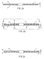
- the digital/analog storage system comprises digital data "bits" (for example, marks on a storage medium such as an optical disk as described later herein), which are analog "near-field optical images" or portions of analog images as shown in Fig. 1b.
- the data bits 19 are of such size that they can be read digitally to obtain a digital record and read in an analog means also to obtain an image. Applicants have found the size of the data bits can be of the order of 10 micron to 500 microns, depending upon the size and resolution requirements of the image.
- the method comprises imaging using an imaging device as described in Fig. 3, which employs near-field optics. This method provides archival storage of images that is independent of a particular digital file format.
- the medium 5 is an optical disk.
- the medium 5 can be any one of a variety such as a CD-rom, writeable CD, DVD, writeable DVD, digital optical tape, etc.
- the medium 5 containing a plurality of near-field optical images 10 recorded as digital bits 19 in a digital data stream 20 shown in an enlarged plan view in Fig 1b.
- Fig. 1b illustrates one of the images 10 that form the data stream 20 where the data stream 20 is actually the same image illustrated in Fig. 1b recorded digitally.
- the length "1" of the image of the image 10 is no greater than about 500 microns.
- the image 10 can be a circle, square, rectangle, ellipse, etc.
- a plurality of images 10 are formed on the medium 5 using near-field optics, which will be explained later in Fig 3.
- the digital data stream 20 is created by forming a plurality of images 10 in a pattern of 16 or 32 bit data streams with start bits and stop bits capable of being read and decoded using known methods for reading and decoding digital data, for example, run length encoding.
- the medium 5 comprises a support structure 12.
- the support structure 12 is polycarbonate.
- the imaging layer 16 that can be coated directly onto the support structure 12.
- the imaging layer 16 is made of a material that changes characteristics when exposed to different wavelengths of light (photosensitive). This material can be, for example, photo-chromic molecules, fluorescent materials and/or silver halide emulsions.
- the imaging layer 16 is coated directly onto the support structure 12, as is well known to those skilled in the art the imaging layer and the support structure can be one and the same. If desired, a protective layer 33 can be applied over the imaging layer 16.
- the protective layer 33 can be formed using acrylic, acrylic polymers, vinyl polymers, polyurethanes, polyesters, and the like.
- the protective layer 33 can also be formed using chemical vapor deposition with material such as oxides and/or nitrides. In either case the protective layer can have a maximum thickness t1 on the order of 100 nanometers, when such near-field recording methods are used.
- modified medium 5 has a digital recording side "A and an analog recording side "B".
- the support structure 12 for example is polycarbonate.
- a digital recording layer 14 is provided on the top surface 17 of the support structure 12.
- the digital recording layer 14 is a dye, for example, metallized phthalocyanine.
- a protective layer 33 can be placed over the digital recording layer 14.
- An analog imaging layer 36 is provided on the bottom surface 34 of the support structure 12.
- the analog imaging layer 36 can be, for example, photo-chromic molecules, fluorescent materials and/or silver halide emulsions.
- a protective layer 37 can be placed over the analog imaging layer 36.
- the protective layers 33 and 37 can be formed using acrylic, acrylic polymers, vinyl polymers, polyurethanes, polyesters, and the like.
- the protective layers 33 and 37 can also be formed using chemical vapor deposition with material such as oxides and/or nitrides. In either case the protective layers can have a maximum thickness of t1 and t2 respectively on the order of 100 nanometers.
- a separate analog recording layer 16 and a separate digital recording layer 14 is provided on the same side of the support structure 12.
- the analog imaging layer 16 can be for example photo-chromic molecules, fluorescent materials and/or silver halide emulsions.
- the digital recording layer 14 is a dye, for example, metallized phthalocyanine.
- a protective layer 33 can be placed over the analog recording layer 16.
- the protective layer 33 can be formed using acrylic, acrylic polymers, vinyl polymers, polyurethanes, polyesters, and the like.
- the protective layer 33 can also be formed using chemical vapor deposition with material such as oxides and/or nitrides. In either case the protective layer can have a maximum thickness t1 on the order of 100 nanometers.
- the analog recording layer 16 is coated directly onto the digital recording layer 16. It is well known by those skilled in the art that a substrate not shown may be required between the two layers.
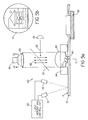
- FIG. 3 there is illustrated an apparatus 50 for forming the image(s) 10 on medium 5.
- the object 51 is a macroscopic representation of the image 10 to be formed on medium 5.
- the image 10 is formed in the imaging layer 16 by transferring light from the object 51.
- the light beam 49 from a light source 53 reflects from a beam splitter 55, through a lens system 62 reflects off the object 51, and passes through an objective lens 54 of conventional design and impinges onto a solid immersion lens (SIL) 56.
- SIL solid immersion lens
- the medium 5 resting on a stage 57 is placed within a critical distance f. Images formed from such a system will have a high lateral spatial resolution in layer 16.
- the light beam 52 passes through an objective lens 54 of conventional design and impinges onto a solid immersion lens (SIL) 56.
- the SIL 56 is positioned within the near-field-coupling limit appropriate for the particular lens in use by the use of a positioning device 58.
- European Patent No. 1083553 provides an example of the means to position an SIL at the appropriate distance from the recording surface, which is incorporated by reference herein.
- Such a positioning device could be a flying head as is used in hard disk storage devices. Alternately there are many known in the art as nano or micro positioning technologies.
- the image 10 can be obtained from a variety of sources such as an illuminated object, a negative, print, and/or a softcopy display.
- the softcopy display can be a CRT, OLED or other similar type device.
- the image 10 can be monochrome or color.
- the method comprises creation of a digital file of the characteristic image to form the image 10.
- a digital file of the image is obtained at step 100.
- Such image digitization methods are well known to those versed in the art.
- the digital file may be obtained by scanning a negative or hard copy of the image such as a print, from a digital camera, from a storage device such as a CD, floppy disk, memory stick, PCMCIA card, etc.
- the digital representation of the image is encoded by any one of a variety of means, such as run length encoding.
- An object 51 of the digital image 10 is created at step 110 using a variety of means such as a softcopy display.
- the image 10 can be black and white or color.
- the softcopy display can be a CRT, organic light emitting diode (OLED) display, or other similar type device.
- OLED organic light emitting diode
- the image 10 is formed onto the medium 5 at step120 so as to produce a digital record and an analog record of the image 10.
- the forming of the digital record typically involves creation of marks or pits in the recording media.
- the data once encoded are read out by recording electronic signals that indicate varying light reflectance levels as a consequence of the presence of the marks.
- the image may be read out using a variety of means including variation in the reflectance, or fluorescence signal.
- the media must have a response dynamic range capable of capturing the intensity variation in the original scene, unless simple black and white images are all that is required.
- the image(s) 10 previously recorded on the layer can be retrieved by optical (analog) means or by digital technology.
- the image(s) 10 are retrieved via the analog method by scanning or optically viewing the medium 5.
- the image(s) 10 can be viewed using magnifying imaging device 80 to retrieve by analog means the image(s) 10 from the medium 5.
- the light beam 82 from a light source 84 reflects from a beam splitter 86 and passes through an objective lens 88 of conventional design and impinges onto a solid immersion lens (SIL) 90.
- SIL solid immersion lens
- the medium 5 in the form of an optical disk resting on a stage 92 is placed within a critical distance f.
- the SIL 90 is positioned within the near-field coupling limit appropriate for the particular lens in use by the use of a positioning device 94.
- a positioning device could be a flying head as is used in hard disk storage devices.
- the light beam 82 is reflected from the image 10 on the imaging layer 16 of the medium 5, passes through the SIL 90, the objective lens 88, and the beam splitter 86, forming the image 10 onto a sensor 96 by a lens system 98.
- the image(s) 10 that have been recorded digitally can be retrieved by digital means using a laser 91, photo detector 93 and logic, and control and memory unit 95 as known by those of ordinary skill in the art.
- FIG. 5b an enlarged view of the image 10 retrieved by the device 80 is shown. Using the imaging device 80, the image 10 is displayed for viewing.
- the modified medium 5 is an optical disk.
- the modified medium 5 can be any one of a variety such as a CD-rom, writeable CD, DVD, writeable DVD, digital optical tape, etc.
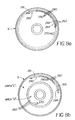
- the modified medium 5 is comprised of side "A" (Fig. 6a) which shows a digital record 200 of the images 240 and 250 illustrated in Figs. 6c and 6d respectively and side "B" which shows a analog record 220 and 230 of images 240 and 250 respectively illustrated in Figs. 6c and 6d as described in Fig. 2b.
- the modified medium 5 allows for both the digital record 200 and analog record 220 of images on the same medium 5.
- Fig. 6c illustrates one of the images 240 that forms part of the digital record 200.
- the same image 240 is also recorded (analog) using near-field optical imaging on side "B" as represented by 220.
- Fig. 6d illustrates another one of the images 250 that forms part of the digital record 200.
- the same image 250 is recorded (analog) using near-field optical imaging on side "B" as represented by 230.
- the images 10 that has been optically recorded on side "B" are retrieved by optical (analog) means and the images 10 that are contained in the digital record 200 on side "A” (see Fig. 6a) are retrieved by digital means.
- the images 10 on side "B” are retrieved via the analog method by optically viewing the medium 5 using near-field optical imaging.
- the images 10 can be viewed using magnifying imaging device 80 to retrieve by analog means the images 10 from the medium 5.
- the light beam 82 from a light source 84 reflects from a beam splitter 86 and passes through an objective lens 88 of conventional design and impinges onto a solid immersion lens (SIL) 90.
- SIL solid immersion lens
- the modified medium 5 in the form of an optical disk resting on a stage 92 is placed within a critical distance f;.
- the SIL 90 is positioned within the near-field coupling limit appropriate for the particular lens in use by the use of a positioning device 94.
- a positioning device could be a flying head as is used in hard disk storage devices.
- the light beam 82 is reflected from the image 10 on the medium 5, passes through the SIL 90, the objective lens 88, and the beam splitter 86, imaging the image 10.
- the images 10 can also be imaged onto the sensor 96 by the lens system 98 by illuminating the image 10 via light beams 97 from a light source 99 which transmit through the modified medium 5.
- the images 10 can be retrieved from the digital record 200 on side "A" by digital means using a laser 91, photo detector 93 and logic, and control and memory unit 95 as known by those of ordinary skill in the art.
- modified medium 5 is an optical disk (as described in Fig. 2c) with the separate analog recording layer 16 and separate digital recording layer 14 provided on the same side of the medium 5.
- the digital recording layer 14 is below the analog recording layer 16.
- the modified medium 5 can be any one of a variety such as a CD-rom, writeable CD, DVD, writeable DVD, etc.
- the modified medium 5 shows digital records 260 and 270 and analog records 280 and 290 respectively.
- the arrows 282, 283, 284, and 285 indicate the images such as shown in Figs. 6c and 6d can extend in a circle around the medium 5.
- the modified medium 5 allows for both the digital records 260 and 270 and analog records 280 and 290 of images on the same side of the medium 5.
- modified medium 5 is an optical disk (as described in Fig. 2c) with the separate analog recording layer 16 and separate digital recording layer 14 provided on the same side of the medium 5.
- the and analog records 280 and 290 can be formed in area "C” and the digital records 260 and 270 can be formed in area "D”.
- FIG. 9 there is illustrated yet another apparatus 50 for forming both the digital data stream 20 and the analog image(s) 10 on medium 5 made in accordance with the present invention.
- the data stream 20 is recorded on the digital recording layer 14 using the laser 91, photo detector 93 and logic, control and memory unit 95 as known by those of ordinary skill in the art.
- the analog image 10 of the object 51 is formed in the imaging layer 16 by transferring light from the object 51.
- the light beam 49 from a light source 53 reflects from a beam splitter 55, through a lens system 62 reflects off the object 51 and passes through an objective lens 54 of conventional design and impinges onto a solid immersion lens (SIL) 56.
- SIL solid immersion lens
- the medium 5 resting on a stage 57 is placed within a critical distance f; images formed from such a system will have a high lateral spatial resolution in layer 16.
- the light beam 52 passes through an objective lens 54 of conventional design and impinges onto a solid immersion lens (SIL) 56.
- the SIL 56 is positioned within the near-field-coupling limit appropriate for the particular lens in use by the use of a positioning device 58.
- European Patent No. 1083553 provides an example of the means to position an SIL at the appropriate distance from the recording surface, which is incorporated by reference herein.
- Such a positioning device could be a flying head as is used in hard disk storage devices. Alternately there are many known in the art as nano or micro positioning technologies.
- the image 10 can be obtained from a variety of sources such as an illuminated object, a negative, print, and/or a softcopy display.
- the softcopy display can be a CRT, OLED or other similar type device.
- the image 10 can be monochrome or color.
- the present invention provides a image storage device and method wherein the storage device includes a photosensitive layer capable of retaining an optical image thereon and wherein the optical images may be written in a digital format that can also be read digitally.
Landscapes
- Engineering & Computer Science (AREA)
- Physics & Mathematics (AREA)
- Chemical & Material Sciences (AREA)
- Nanotechnology (AREA)
- Mathematical Physics (AREA)
- Theoretical Computer Science (AREA)
- Crystallography & Structural Chemistry (AREA)
- Optics & Photonics (AREA)
- Optical Recording Or Reproduction (AREA)
- Optical Record Carriers And Manufacture Thereof (AREA)
- Projection-Type Copiers In General (AREA)
- Signal Processing For Digital Recording And Reproducing (AREA)
Abstract

Description
Claims (9)
- A method of making a digital and analog image storage product, comprising the steps of:providing a photosensitive medium capable of forming an image thereon when exposed to light and is also capable of storing data in a digital format; andproviding an analog and digital image on said medium simultaneously using a near-field-imaging device.
- The method according to claims 1, 4, or 5 wherein near field optical device provides images having a size not greater than about 500 microns.
- The method according to claims 1, 4, or 5 wherein said photosensitive medium has a support structure on which a layer of a photosensitive material is placed on said product by chemical vapor deposition.
- A photosensitive data storage product made of a material on which digital data may be formed, the digital data comprising discreet image elements formed by exposure to light.
- A data storage product having a support having a first surface and a second surface, said first surface having a layer made of a material on which digital data may be formed, said second surface having photosensitive layer made of a material on which analog image may be formed.
- A method for encoding digital data and image data on a storage product such that optical images or portions of optical images formed thereon can be read optically without interfering with reading of the digital data, comprising the steps of:forming digital data in a storage product;forming optical images on said storage product in a separate step.
- A method according to claim 6 wherein said digital data is formatted in a first portion of the product and the optical images are formed on a second portion of said product.
- A storage device having a photosensitive layer capable of retaining an optical image thereon and wherein the optical images may be written in a digital format that can also be read digitally.
- A data storage product having a support having a recording surface, said recording surface having a first section where digital recording may be placed and a second section where an analog recording may be placed.
Applications Claiming Priority (2)
| Application Number | Priority Date | Filing Date | Title |
|---|---|---|---|
| US45805 | 1997-05-07 | ||
| US10/045,805 US7294446B2 (en) | 2001-10-29 | 2001-10-29 | Digital analog recording using near field optical imaging |
Publications (3)
| Publication Number | Publication Date |
|---|---|
| EP1310950A2 true EP1310950A2 (en) | 2003-05-14 |
| EP1310950A3 EP1310950A3 (en) | 2006-08-30 |
| EP1310950B1 EP1310950B1 (en) | 2010-12-22 |
Family
ID=21939980
Family Applications (1)
| Application Number | Title | Priority Date | Filing Date |
|---|---|---|---|
| EP02079322A Expired - Lifetime EP1310950B1 (en) | 2001-10-29 | 2002-10-17 | Digital/analog recording using near field optical imaging |
Country Status (4)
| Country | Link |
|---|---|
| US (1) | US7294446B2 (en) |
| EP (1) | EP1310950B1 (en) |
| JP (1) | JP4117180B2 (en) |
| DE (1) | DE60238661D1 (en) |
Cited By (2)
| Publication number | Priority date | Publication date | Assignee | Title |
|---|---|---|---|---|
| EP2105921A1 (en) | 2008-03-28 | 2009-09-30 | Commissariat a L'Energie Atomique | Method for storing images and associated storage medium |
| FR2934404A1 (en) * | 2008-07-24 | 2010-01-29 | Commissariat Energie Atomique | DEVICE FOR RECORDING GRAPHIC DATA ON A SUPPORT. |
Families Citing this family (3)
| Publication number | Priority date | Publication date | Assignee | Title |
|---|---|---|---|---|
| EP1576419A4 (en) * | 2002-12-09 | 2006-07-12 | Pixelligent Technologies Llc | PROGRAMMABLE PHOTOLITHOGRAPHIC MASK AND PHOTO-INSTABLE MATERIALS BASED ON NANOMETRICALLY SIZED SEMICONDUCTOR PARTICLES AND THEIR APPLICATIONS |
| CN101729840A (en) * | 2009-12-17 | 2010-06-09 | 于培宁 | Storage processing method utilizing video image characteristic sequence |
| CN105324816A (en) | 2013-05-17 | 2016-02-10 | 道格卡森联合公司 | Image file disk |
Family Cites Families (27)
| Publication number | Priority date | Publication date | Assignee | Title |
|---|---|---|---|---|
| US3465352A (en) * | 1966-05-11 | 1969-09-02 | Ncr Co | Information processing systems using lasers |
| GB1242527A (en) * | 1967-10-20 | 1971-08-11 | Kodak Ltd | Optical instruments |
| US4322759A (en) * | 1970-03-27 | 1982-03-30 | Zenzefilis George E | Method and apparatus for recording and reproducing video |
| US3701999A (en) * | 1970-08-21 | 1972-10-31 | Ncr Co | Computer output laser microform recording system |
| US3998989A (en) * | 1974-09-20 | 1976-12-21 | Ball Brothers Research Corporation | Method and composition for lubricating and lubricated substrates |
| US4219704A (en) * | 1974-10-21 | 1980-08-26 | Eli S. Jacobs | Record playback apparatus for optical data records |
| US4346449A (en) | 1976-09-16 | 1982-08-24 | Energy Conversion Devices, Inc. | Data storage and retrieval system |
| JPS58100235A (en) * | 1981-12-11 | 1983-06-14 | Victor Co Of Japan Ltd | Information recording disk and its character recording system |
| JPS595248A (en) * | 1982-07-01 | 1984-01-12 | Yamatoya Shokai:Kk | Correction method using photochromic substance |
| US5031168A (en) | 1986-02-05 | 1991-07-09 | Information Storage, Inc. | Apparatus and method for increasing storage capacity of recording media |
| US4884260A (en) * | 1986-04-23 | 1989-11-28 | Drexler Technology Corporation | Data recording system for optical memory tape |
| JPH01144247A (en) * | 1987-11-30 | 1989-06-06 | Brother Ind Ltd | disk |
| US5161233A (en) | 1988-05-17 | 1992-11-03 | Dai Nippon Printing Co., Ltd. | Method for recording and reproducing information, apparatus therefor and recording medium |
| DD289911A7 (en) | 1988-12-30 | 1991-05-16 | Defa Studio Babelsberg Gmbh,De | METHOD FOR RECORDING AND PLAYING AN ANALOG AND DIGITAL LIGHT TONE |
| US5272330A (en) | 1990-11-19 | 1993-12-21 | At&T Bell Laboratories | Near field scanning optical microscope having a tapered waveguide |
| US5470627A (en) * | 1992-03-06 | 1995-11-28 | Quantum Corporation | Double-sided optical media for a disk storage device |
| JP3466650B2 (en) * | 1993-03-12 | 2003-11-17 | 入江 正浩 | Rewritable optical recording method |
| US5721687A (en) | 1995-02-01 | 1998-02-24 | The Regents Of The University Of California Office Of Technology Transfer | Ultrahigh vacuum focused ion beam micromill and articles therefrom |
| IL119020A (en) * | 1996-08-06 | 2000-02-29 | Elop Electrooptics Ind Ltd | Photochromic supra-density optical memory |
| JPH1186505A (en) | 1997-09-10 | 1999-03-30 | Fuji Photo Film Co Ltd | Recording medium with index print and its formation |
| JPH11110816A (en) * | 1997-10-01 | 1999-04-23 | Hitachi Maxell Ltd | Optical recording medium and image forming method |
| JP2000030256A (en) | 1998-07-07 | 2000-01-28 | Seiko Instruments Inc | Optical recording and reproducing method, recording medium used in optical recording and reproducing and optical recording and reproducing device |
| US6442296B1 (en) * | 1998-11-06 | 2002-08-27 | Storage Technology Corporation | Archival information storage on optical medium in human and machine readable format |
| US6884553B2 (en) * | 1999-03-11 | 2005-04-26 | Mitsubishi Chemical Corporation | Near-field optical recording medium and near-field optical recording method |
| JP2001076382A (en) * | 1999-09-07 | 2001-03-23 | Minolta Co Ltd | Optical recording medium |
| JP3956547B2 (en) | 1999-09-07 | 2007-08-08 | ソニー株式会社 | Optical recording apparatus, optical recording and / or reproducing method |
| JP2001184691A (en) * | 1999-12-22 | 2001-07-06 | Minolta Co Ltd | Recording medium, optical head and recording/ reproducing device |
-
2001
- 2001-10-29 US US10/045,805 patent/US7294446B2/en not_active Expired - Fee Related
-
2002
- 2002-10-17 EP EP02079322A patent/EP1310950B1/en not_active Expired - Lifetime
- 2002-10-17 DE DE60238661T patent/DE60238661D1/en not_active Expired - Lifetime
- 2002-10-29 JP JP2002313650A patent/JP4117180B2/en not_active Expired - Fee Related
Cited By (4)
| Publication number | Priority date | Publication date | Assignee | Title |
|---|---|---|---|---|
| EP2105921A1 (en) | 2008-03-28 | 2009-09-30 | Commissariat a L'Energie Atomique | Method for storing images and associated storage medium |
| US8310512B2 (en) | 2008-03-28 | 2012-11-13 | Commissariat A L'energie Atomique | Method of strong images and corresponding storage medium |
| FR2934404A1 (en) * | 2008-07-24 | 2010-01-29 | Commissariat Energie Atomique | DEVICE FOR RECORDING GRAPHIC DATA ON A SUPPORT. |
| EP2172933A1 (en) | 2008-07-24 | 2010-04-07 | Commissariat à l'Energie Atomique (Etablissement Public) | Apparatus for recording graphical data on a medium |
Also Published As
| Publication number | Publication date |
|---|---|
| EP1310950A3 (en) | 2006-08-30 |
| US7294446B2 (en) | 2007-11-13 |
| JP2003233934A (en) | 2003-08-22 |
| DE60238661D1 (en) | 2011-02-03 |
| EP1310950B1 (en) | 2010-12-22 |
| US20030081300A1 (en) | 2003-05-01 |
| JP4117180B2 (en) | 2008-07-16 |
Similar Documents
| Publication | Publication Date | Title |
|---|---|---|
| US5125750A (en) | Optical recording system employing a solid immersion lens | |
| US6324129B1 (en) | Near field magneto-optical head having read and write pinhole apertures | |
| EP0126126A1 (en) | Medium for recording visual images and laser written data | |
| EP1158503A3 (en) | Optical pickup apparatus, objective lens, apparatus for reproducing and/or recording optical information recording medium | |
| Wu et al. | Imaging with solid immersion lenses, spatial resolution, and applications | |
| JP2001502100A (en) | Confocal optical microscope system for multi-layer data storage and reading | |
| US6522616B1 (en) | Multilayer optical information storage medium based on incoherent signal | |
| US7080857B2 (en) | Authentication using near-field optical imaging | |
| US7294446B2 (en) | Digital analog recording using near field optical imaging | |
| JP2003006913A (en) | Near-field optical head | |
| US20060250932A1 (en) | Optical information storage unit | |
| EP0978829A1 (en) | Near field optical memory head | |
| EP1031975A3 (en) | Optical information medium, stamper for manufacturing transparent substrate therefor and recording method therefor | |
| US20090109828A1 (en) | Optical System With Superlens | |
| US4903256A (en) | Card including rotatory system optical recording medium | |
| EP1616168B1 (en) | Biochip with independent recognition areas and optical format and float scanning thereof | |
| JP4610855B2 (en) | Near-field light generating element, near-field light recording device, and near-field light microscope | |
| JPH07220281A (en) | Optical disc and optical disc system | |
| KR100504775B1 (en) | High refractive index immersion lens for optical recording and reproducing system and manufacturing method thereof | |
| JP4593666B2 (en) | Near-field light generating element, near-field light recording device, and near-field light microscope | |
| JP4162317B2 (en) | Near-field optical memory head | |
| KR100464008B1 (en) | Manufacturing method of spherical lens, lens module and solid immersion lens, optical pick-up head for near field recorder | |
| JPS6185645A (en) | optical memory card | |
| Itao et al. | Present status and future of opto-mechatronics | |
| Shamir | New technologies for records management |
Legal Events
| Date | Code | Title | Description |
|---|---|---|---|
| PUAI | Public reference made under article 153(3) epc to a published international application that has entered the european phase |
Free format text: ORIGINAL CODE: 0009012 |
|
| AK | Designated contracting states |
Designated state(s): AT BE BG CH CY CZ DE DK EE ES FI FR GB GR IE IT LI LU MC NL PT SE SK TR |
|
| AX | Request for extension of the european patent |
Extension state: AL LT LV MK RO SI |
|
| PUAL | Search report despatched |
Free format text: ORIGINAL CODE: 0009013 |
|
| AK | Designated contracting states |
Kind code of ref document: A3 Designated state(s): AT BE BG CH CY CZ DE DK EE ES FI FR GB GR IE IT LI LU MC NL PT SE SK TR |
|
| AX | Request for extension of the european patent |
Extension state: AL LT LV MK RO SI |
|
| RIC1 | Information provided on ipc code assigned before grant |
Ipc: G11B 7/20 20060101ALI20060725BHEP Ipc: G11B 7/24 20060101ALI20060725BHEP Ipc: G11B 7/0045 20060101ALI20060725BHEP Ipc: G11B 7/013 20060101AFI20060725BHEP |
|
| 17P | Request for examination filed |
Effective date: 20061222 |
|
| AKX | Designation fees paid |
Designated state(s): DE GB |
|
| 17Q | First examination report despatched |
Effective date: 20070824 |
|
| GRAP | Despatch of communication of intention to grant a patent |
Free format text: ORIGINAL CODE: EPIDOSNIGR1 |
|
| GRAS | Grant fee paid |
Free format text: ORIGINAL CODE: EPIDOSNIGR3 |
|
| GRAA | (expected) grant |
Free format text: ORIGINAL CODE: 0009210 |
|
| AK | Designated contracting states |
Kind code of ref document: B1 Designated state(s): DE GB |
|
| REG | Reference to a national code |
Ref country code: GB Ref legal event code: FG4D |
|
| REF | Corresponds to: |
Ref document number: 60238661 Country of ref document: DE Date of ref document: 20110203 Kind code of ref document: P |
|
| REG | Reference to a national code |
Ref country code: DE Ref legal event code: R096 Ref document number: 60238661 Country of ref document: DE Effective date: 20110203 |
|
| PLBE | No opposition filed within time limit |
Free format text: ORIGINAL CODE: 0009261 |
|
| STAA | Information on the status of an ep patent application or granted ep patent |
Free format text: STATUS: NO OPPOSITION FILED WITHIN TIME LIMIT |
|
| 26N | No opposition filed |
Effective date: 20110923 |
|
| REG | Reference to a national code |
Ref country code: DE Ref legal event code: R097 Ref document number: 60238661 Country of ref document: DE Effective date: 20110923 |
|
| PGFP | Annual fee paid to national office [announced via postgrant information from national office to epo] |
Ref country code: GB Payment date: 20120925 Year of fee payment: 11 |
|
| PGFP | Annual fee paid to national office [announced via postgrant information from national office to epo] |
Ref country code: DE Payment date: 20121031 Year of fee payment: 11 |
|
| REG | Reference to a national code |
Ref country code: DE Ref legal event code: R119 Ref document number: 60238661 Country of ref document: DE |
|
| GBPC | Gb: european patent ceased through non-payment of renewal fee |
Effective date: 20131017 |
|
| REG | Reference to a national code |
Ref country code: DE Ref legal event code: R079 Ref document number: 60238661 Country of ref document: DE Free format text: PREVIOUS MAIN CLASS: G11B0007004500 Ipc: G11B0007240000 |
|
| PG25 | Lapsed in a contracting state [announced via postgrant information from national office to epo] |
Ref country code: GB Free format text: LAPSE BECAUSE OF NON-PAYMENT OF DUE FEES Effective date: 20131017 |
|
| REG | Reference to a national code |
Ref country code: DE Ref legal event code: R119 Ref document number: 60238661 Country of ref document: DE Effective date: 20140501 Ref country code: DE Ref legal event code: R079 Ref document number: 60238661 Country of ref document: DE Free format text: PREVIOUS MAIN CLASS: G11B0007004500 Ipc: G11B0007240000 Effective date: 20140702 |
|
| PG25 | Lapsed in a contracting state [announced via postgrant information from national office to epo] |
Ref country code: DE Free format text: LAPSE BECAUSE OF NON-PAYMENT OF DUE FEES Effective date: 20140501 |