EP1312740A1 - Türsystem - Google Patents
Türsystem Download PDFInfo
- Publication number
- EP1312740A1 EP1312740A1 EP02025917A EP02025917A EP1312740A1 EP 1312740 A1 EP1312740 A1 EP 1312740A1 EP 02025917 A EP02025917 A EP 02025917A EP 02025917 A EP02025917 A EP 02025917A EP 1312740 A1 EP1312740 A1 EP 1312740A1
- Authority
- EP
- European Patent Office
- Prior art keywords
- door
- door leaf
- door system
- profile
- hinges
- Prior art date
- Legal status (The legal status is an assumption and is not a legal conclusion. Google has not performed a legal analysis and makes no representation as to the accuracy of the status listed.)
- Withdrawn
Links
- 229910000831 Steel Inorganic materials 0.000 claims abstract description 4
- 239000010959 steel Substances 0.000 claims abstract description 4
- 239000011521 glass Substances 0.000 description 10
- 238000004519 manufacturing process Methods 0.000 description 5
- 239000000463 material Substances 0.000 description 4
- 238000004873 anchoring Methods 0.000 description 3
- 238000010276 construction Methods 0.000 description 3
- 238000009434 installation Methods 0.000 description 3
- 230000015572 biosynthetic process Effects 0.000 description 2
- 230000006378 damage Effects 0.000 description 2
- 230000000007 visual effect Effects 0.000 description 2
- 208000027418 Wounds and injury Diseases 0.000 description 1
- 229910052782 aluminium Inorganic materials 0.000 description 1
- XAGFODPZIPBFFR-UHFFFAOYSA-N aluminium Chemical compound [Al] XAGFODPZIPBFFR-UHFFFAOYSA-N 0.000 description 1
- 239000011324 bead Substances 0.000 description 1
- 239000003086 colorant Substances 0.000 description 1
- 238000005520 cutting process Methods 0.000 description 1
- 230000001419 dependent effect Effects 0.000 description 1
- 208000014674 injury Diseases 0.000 description 1
- 229910052751 metal Inorganic materials 0.000 description 1
- 239000002184 metal Substances 0.000 description 1
- 230000007935 neutral effect Effects 0.000 description 1
- 239000004033 plastic Substances 0.000 description 1
- 238000002360 preparation method Methods 0.000 description 1
- 238000007789 sealing Methods 0.000 description 1
- 229910001220 stainless steel Inorganic materials 0.000 description 1
- 239000010935 stainless steel Substances 0.000 description 1
- 238000003860 storage Methods 0.000 description 1
- 238000003466 welding Methods 0.000 description 1
- 239000002023 wood Substances 0.000 description 1
Images


Classifications
-
- E—FIXED CONSTRUCTIONS
- E06—DOORS, WINDOWS, SHUTTERS, OR ROLLER BLINDS IN GENERAL; LADDERS
- E06B—FIXED OR MOVABLE CLOSURES FOR OPENINGS IN BUILDINGS, VEHICLES, FENCES OR LIKE ENCLOSURES IN GENERAL, e.g. DOORS, WINDOWS, BLINDS, GATES
- E06B1/00—Border constructions of openings in walls, floors, or ceilings; Frames to be rigidly mounted in such openings
- E06B1/04—Frames for doors, windows, or the like to be fixed in openings
- E06B1/52—Frames specially adapted for doors
-
- E—FIXED CONSTRUCTIONS
- E05—LOCKS; KEYS; WINDOW OR DOOR FITTINGS; SAFES
- E05D—HINGES OR SUSPENSION DEVICES FOR DOORS, WINDOWS OR WINGS
- E05D7/00—Hinges or pivots of special construction
- E05D7/0009—Adjustable hinges
- E05D7/0018—Adjustable hinges at the hinge axis
- E05D7/0027—Adjustable hinges at the hinge axis in an axial direction
-
- E—FIXED CONSTRUCTIONS
- E05—LOCKS; KEYS; WINDOW OR DOOR FITTINGS; SAFES
- E05D—HINGES OR SUSPENSION DEVICES FOR DOORS, WINDOWS OR WINGS
- E05D7/00—Hinges or pivots of special construction
- E05D7/0009—Adjustable hinges
- E05D7/0018—Adjustable hinges at the hinge axis
- E05D7/0045—Adjustable hinges at the hinge axis in a radial direction
- E05D7/0054—Adjustable hinges at the hinge axis in a radial direction by means of eccentric parts
-
- E—FIXED CONSTRUCTIONS
- E05—LOCKS; KEYS; WINDOW OR DOOR FITTINGS; SAFES
- E05D—HINGES OR SUSPENSION DEVICES FOR DOORS, WINDOWS OR WINGS
- E05D7/00—Hinges or pivots of special construction
- E05D7/08—Hinges or pivots of special construction for use in suspensions comprising two spigots placed at opposite edges of the wing, especially at the top and the bottom, e.g. trunnions
- E05D7/081—Hinges or pivots of special construction for use in suspensions comprising two spigots placed at opposite edges of the wing, especially at the top and the bottom, e.g. trunnions the pivot axis of the wing being situated near one edge of the wing, especially at the top and bottom, e.g. trunnions
-
- E—FIXED CONSTRUCTIONS
- E06—DOORS, WINDOWS, SHUTTERS, OR ROLLER BLINDS IN GENERAL; LADDERS
- E06B—FIXED OR MOVABLE CLOSURES FOR OPENINGS IN BUILDINGS, VEHICLES, FENCES OR LIKE ENCLOSURES IN GENERAL, e.g. DOORS, WINDOWS, BLINDS, GATES
- E06B3/00—Window sashes, door leaves, or like elements for closing wall or like openings; Layout of fixed or moving closures, e.g. windows in wall or like openings; Features of rigidly-mounted outer frames relating to the mounting of wing frames
- E06B3/02—Wings made completely of glass
-
- E—FIXED CONSTRUCTIONS
- E05—LOCKS; KEYS; WINDOW OR DOOR FITTINGS; SAFES
- E05D—HINGES OR SUSPENSION DEVICES FOR DOORS, WINDOWS OR WINGS
- E05D11/00—Additional features or accessories of hinges
- E05D11/04—Additional features or accessories of hinges relating to the use of free balls as bearing-surfaces
-
- E—FIXED CONSTRUCTIONS
- E05—LOCKS; KEYS; WINDOW OR DOOR FITTINGS; SAFES
- E05Y—INDEXING SCHEME ASSOCIATED WITH SUBCLASSES E05D AND E05F, RELATING TO CONSTRUCTION ELEMENTS, ELECTRIC CONTROL, POWER SUPPLY, POWER SIGNAL OR TRANSMISSION, USER INTERFACES, MOUNTING OR COUPLING, DETAILS, ACCESSORIES, AUXILIARY OPERATIONS NOT OTHERWISE PROVIDED FOR, APPLICATION THEREOF
- E05Y2800/00—Details, accessories and auxiliary operations not otherwise provided for
- E05Y2800/67—Materials; Strength alteration thereof
- E05Y2800/672—Glass
-
- E—FIXED CONSTRUCTIONS
- E05—LOCKS; KEYS; WINDOW OR DOOR FITTINGS; SAFES
- E05Y—INDEXING SCHEME ASSOCIATED WITH SUBCLASSES E05D AND E05F, RELATING TO CONSTRUCTION ELEMENTS, ELECTRIC CONTROL, POWER SUPPLY, POWER SIGNAL OR TRANSMISSION, USER INTERFACES, MOUNTING OR COUPLING, DETAILS, ACCESSORIES, AUXILIARY OPERATIONS NOT OTHERWISE PROVIDED FOR, APPLICATION THEREOF
- E05Y2900/00—Application of doors, windows, wings or fittings thereof
- E05Y2900/10—Application of doors, windows, wings or fittings thereof for buildings or parts thereof
- E05Y2900/13—Type of wing
- E05Y2900/132—Doors
Definitions
- the invention relates to a door system with at least one Door leaf that swivels by means of at least two hinges is attached.
- the door attachment is in the generally only possible on the opening side.
- the usual door structure the adjustment of the door leaf and that Attach the seal (e.g. for apartment entrance doors) relatively complex, as well as the installation of increasingly desired Glass doors.
- the construction of a common door system is therefore relatively complex, as well as the preparation and storage matching door leaf. This approach contributes significantly to the Total cost of door manufacturing, with one Cost savings due to the high wage share for assembly is hardly possible.
- Another disadvantage of such a door installation is that low anchoring stability of the door frame, so that the Hinges often need to be readjusted to prevent the formation of To be able to avoid joints and thus cold bridges.
- the object of the present invention is therefore a To create door system that described the above Avoids disadvantages and is particularly stable, simple and is inexpensive to manufacture.
- the hinges are in the Corner area attached to the upper and lower edge of the door leaf, so that a continuous door leaf can be used.
- the stationary hinge parts can be directly on the floor and on attached to the ceiling.
- the door frame if applicable consists preferably of a narrow steel hollow profile, which in can be attached to the masonry in a stable manner and thus for serves to securely anchor the door leaf. It can Door leaf almost anywhere within the reveal area be positioned and made of different materials consist, in particular of wood, glass or plastic.
- the Hinges in the corner area are securely anchored, especially through heavy-duty anchors in the floor and ceiling or by welding the frame-side hinge part to the Door frame fastened particularly stable.
- Another advantage is the fact that the adjustment of the Door leaf on the corresponding hinges quickly and easily can be done.
- This approach is very advantageous because the Assembly of the individual hinges can be done relatively easily and they can also be easily manufactured. It is advantageous further that the door frame by means of an aperture profile on Wall structure, especially the masonry, in a stable manner fasten, so that a gap formation and thus cold bridges or leaks are largely excluded.
- Advantageous is also that with glass doors on complicated to manufacture Glazing beads or frames for bordering largely dispensed with can be.
- a have a door frame 2 on which a door leaf 3 is fixed via hinges 4.
- the stationary or building-side hinge parts 4a can, however, also directly be attached to the ceiling and floor, especially by means of Heavy duty anchors or dowels are screwed. Thereby this as well as the door frame 2 within the wall reveal can be positioned anywhere.
- two hinges 4 are thus attached, namely in the upper Area on the upper edge 3a and in the lower area on the Lower edge 3b.
- the angular hinges 4 each exist from a building side and a door leaf side Hinge part 4a or 4b, the hinge part on the building side 4a is welded to the door frame 2 here.
- the respective Door leaf-side hinge part 4b is in the corresponding fold on the lower edge 3b of the continuous door leaf 3 with a perfect fit used and preferably screwed.
- the dashed line in Fig. 2 The hinge part 4b shown preferably consists of an approximately 1 cm thick steel material.
- the underlying stationary Hinge part 4a is congruent on the floor or on the door frame 2 attached, especially welded.
- the door frame 2 or its hollow support profile 10 see FIG. 9), in particular in the area of the hinges 4 on it hidden outside with inserted screws 8, from the inside anchored here to the masonry or other wall construction.
- the door frame 2 with the welded hinge parts 4a therefore preferably consists of an “inner” support profile 10 (see Fig. 9), which is attached to the wall structure and is covered by an aperture profile 9.
- the aperture profile 9 at the same time forms the fold area to the door leaf 3 and preferably engages with locking hooks 11 in openings 2a of the Carrier profile 10 a. Bends of the Carrier profile 10 in the manner of a spring snap connection intervene and form-fit this in the manner of a clamp embrace. It is also provided that the necessary one Seal is attached to the door leaf 3, e.g. as all around Rubber strip.
- a door leaf (Movable) hinge part 4b preferably a flat one Metal angle (drawn in dashed lines) used.
- Hinge parts 4a, 4b can also stainless steel materials or Aluminum plates with a polished surface can be used.
- the Hinge joint protrudes from the one pointing up here Outer surface of the door leaf 3 by about half the door leaf thickness before, while anchoring the door frame 2 in the masonry is plastered. With this "sunken” arrangement the Risk of injury (e.g. from children playing) on the edges of the Hinges 4 significantly reduced, as well Soiling tendency.
- the stationary, frame-side Hinge part 4a also at the upper corner area of the door frame 2 is welded on. Alternatively, this could also be done at the The ceiling of the building must be screwed on.
- an eccentric screw 6 Side adjustment of the door leaf 3 stored and with a so-called. Set screw secured. This results in a special one Secure anchoring because lateral forces are well supported.
- FIG. 5, 6 and 7 are corresponding views for the Attachment of a glass door shown. It is provided that the door leaf-side hinge parts 4b compared to that in Fig. 2 concealed fastening in the manner of a concealed area Clip placed on the main surface of the door leaf 3 and are screwed. But it is also possible to move these Arrange hinge parts 4b flush with the main surface, with the back recessed to maintain a good overall look is arranged. It is preferably provided that the edge of the All-round glass plate with surrounding glass strips 12 (blackened shown) is provided. This will damage the Door leaf 3 in the rebate area when it hits the door frame 2 safely avoided.
- FIG. 8 shows an embodiment similar to that shown in FIG. 2, but with a double fold 7 for improved sealing, so that this door system is also suitable for apartment or corridor doors suitable.
- the manufacture starting from the shell dimensions of the door leaf 3 and the door frame 2 first the Hinges 4 on the correspondingly cut support profile 10 welded. Then according to the outline movable, d. H. with the door leaf 3 with pivoting Hinge parts 4b on the top edge 3a or bottom edge of the door leaf 3b attached, in particular by screwing on the door leaf 3.
- the outline of the hinge part 4b faces the Thickness of the door leaf 3 has a slightly smaller external dimension, so that the first can be used concealed in the fold area.
- the lower adjusting screw is used for assembly on the construction site 5 used to adjust the height of the door panel 3, while the Side adjustment with the upper eccentric screw 6 in simple and can be done more quickly.
- one graded running edge on the outer edge of the panel profile 9 can simple way of creating the visual impression of decorative strips are, so that the separate application of such strips is not necessary.
- An end edge 9a of the panel profile 9 can also be used as Plastering edge to assist in plastering the door reveal serve.
- the panel profile 9 can in addition to the brackets Locking hook 11 also by an unspecified Screw connection to the support profile 10 are attached.
Landscapes
- Engineering & Computer Science (AREA)
- Mechanical Engineering (AREA)
- Civil Engineering (AREA)
- Structural Engineering (AREA)
- Securing Of Glass Panes Or The Like (AREA)
- Hinges (AREA)
- Wing Frames And Configurations (AREA)
- Door And Window Frames Mounted To Openings (AREA)
Abstract
Zur Schaffung eines einfach aufgebauten Türsystems mit wenigstens einem Türblatt (3), das mittels wenigstens zwei Scharnieren (4) schwenkbar befestigt ist, wird vorgeschlagen, daß die Scharniere (4) im Eckbereich an der Ober- und Unterkante (3a, 3b) des Türblattes (3) befestigt sind. <IMAGE>
Description
Die Erfindung betrifft ein Türsystem mit wenigstens einem
Türblatt, das mittels wenigstens zwei Scharnieren schwenkbar
befestigt ist.
Beim Haus- oder Wohnungsausbau sollen Türen, insbesondere im
Innenbereich möglichst rasch montiert werden können, um den
Kostenanteil zu senken. Üblicherweise werden dabei zunächst
Türrahmen oder Zargen gesetzt und am umgebenden Mauerwerk
verankert, bevor das Türblatt an Scharnieren bzw. Türbändern
eingehängt wird. Dieser Zargenaufbau bedingt jedoch einen
erheblichen Materialaufwand, insbesondere bei dicken Wänden.
Dort sind häufig nur noch kostspielige Sonderanfertigungen durch
den Schreiner möglich. Viele Bauherren wünschen sich jedoch,
insbesondere aus gestalterischen Gesichtspunkten, einen
leibungsneutralen Einbau, z.B. das mittige Einsetzen der Tür in
der Leibungsfläche.
Bei einem Zargenaufbau ist jedoch die Türanbringung im
allgemeinen nur an der Öffnungsseite möglich. Zudem ist beim
üblichen Türenaufbau das Einstellen des Türblattes und das
Anbringen der Dichtung (z.B. bei Wohnungseingangstüren) relativ
aufwendig, ebenso wie der Einbau von zunehmend gewünschten
Glastüren. Der Aufbau eines üblichen Türsystems ist daher
relativ aufwendig, ebenso wie die Vorbereitung und Lagerhaltung
passender Türflügel. Diese Vorgehensweise trägt erheblich zu den
Gesamtkosten bei der Türherstellung bei, wobei eine
Kosteneinsparung wegen des hohen Lohnanteils für die Montage
kaum möglich ist.
Ein weiterer Nachteil eines derartigen Türeinbaus liegt in der
geringen Verankerungsstabilität der Türzarge, so daß die
Scharniere häufig nachjustiert werden müssen, um die Bildung von
Fugen und damit Kältebrücken vermeiden zu können.
Die Aufgabe der vorliegenden Erfindung besteht somit darin, ein
Türsystem zu schaffen, das die vorstehend beschriebenen
Nachteile vermeidet und besonders stabil, einfach und
kostengünstig herstellbar ist.
Diese Aufgabe wird gelöst durch ein Türsystem nach Anspruch 1.
Vorteilhafte Ausbildungen sind Gegenstand der Merkmale der
Unteransprüche.
Bei dem vorgeschlagenen Türsystem sind die Scharniere im
Eckbereich an der Ober- und Unterkante des Türblattes befestigt,
so daß ein durchgängiges Türblatt verwendet werden kann. Die
stationären Scharnierteile können dabei direkt am Boden und an
der Decke befestigt werden. Der ggf. vorgesehene Türrahmen
besteht bevorzugt aus einem schmalen Stahl-Hohlprofil, das in
stabiler Weise am Mauerwerk angebracht werden kann und somit zur
sicheren Verankerung des Türblattes dient. Dabei kann das
Türblatt innerhalb der Leibungsfläche nahezu beliebig
positioniert werden und aus unterschiedlichen Materialien
bestehen, insbesondere aus Holz, Glas oder Kunststoff. Die
Scharniere im Eckbereich sind dabei sicher verankert,
insbesondere durch Schwerlastanker im Boden und der Decke oder
durch Verschweißen des rahmenseitigen Scharnierteils mit dem
Türrahmen besonders stabil befestigt.
Ein weiterer Vorteil ist darin zu sehen, daß die Justierung des
Türblattes an den entsprechenden Scharnieren einfach und rasch
erfolgen kann. Diese Vorgehensweise ist sehr vorteilhaft, da die
Montage der einzelnen Scharniere relativ einfach erfolgen kann
und diese zudem einfach gefertigt werden können. Vorteilhaft ist
weiterhin, daß der Türrahmen mittels eines Blendenprofils am
Wandaufbau, insbesondere dem Mauerwerk in stabiler Weise zu
befestigen ist, so daß eine Fugenbildung und somit Kältebrücken
oder Undichtigkeiten weitgehend ausgeschlossen sind. Vorteilhaft
ist ferner, daß bei Glastüren auf kompliziert zu fertigende
Glasleisten oder Rahmen zur Umgrenzung weitgehend verzichtet
werden kann.
Bei dieser vereinfachten Herstellungsweise mit sicherer
Verankerung und frei wählbarer Optik sind somit Türsysteme mit
weitgehend verdeckt angeordneten Scharnieren kostengünstig
herzustellen, insbesondere auch Zierelemente am schmalbauenden
Türrahmen auf einfache Art und Weise durch aufgesteckte
Blendenprofile individuell zu verwirklichen.
Nachstehend werden mehrere Ausführungsbeispiele der vorliegenden
Erfindung anhand der Figuren näher beschrieben. Hierbei zeigen:
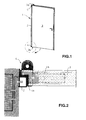
- Fig. 1
- eine Perspektivansicht auf eine neuerungsgemäße Tür;
- Fig. 2
- eine vergrößerte Draufsicht auf ein unteres Scharnier mit Teil-Querschnitt der Tür entlang dem in Fig. 1 strichliert angedeuteten Schnittkreis;
- Fig. 3
- eine Seitenansicht auf das in Fig. 2 dargestellte untere Scharnier;
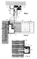
- Fig. 4
- eine Seitenansicht auf das obere Scharnier mit geschlossenem Türblatt im Querschnitt;
- Fig. 5
- eine Ansicht gemäß Fig. 2 mit einem Glas-Türblatt;
- Fig. 6
- eine Ansicht gemäß Fig. 3 mit einem Glas-Türblatt;
- Fig. 7
- eine Ansicht gemäß Fig. 4 mit einem Glas-Türblatt;
- Fig. 8
- eine Ansicht ähnlich Fig. 2 in der Ausführung als Korridortüre mit Doppelfalz; und
- Fig. 9
- einen Querschnitt durch eine bevorzugte Ausführung des Türrahmens.
Die nachfolgende Beschreibung bezieht sich aus Gründen der
Einfachheit auf eine einflügelige Tür, wobei entsprechende
Ausführungen sinngemäß auch für mehrflügelige Türen gelten
sollen. Wie in Fig. 1 schematisch dargestellt, kann ein
neuerungsgemäßes Türsystem 1 einen Türrahmen 2 aufweisen, an dem
ein Türblatt 3 über Scharniere 4 fixiert ist. Die stationären
bzw. gebäudeseitigen Scharnierteile 4a können jedoch auch direkt
an der Decke und dem Boden befestigt sein, insbesondere mittels
Schwerlastankern oder Dübeln verschraubt sein. Dadurch sind
diese ebenso wie der Türrahmen 2 innerhalb der Wandleibung an
beliebiger Stelle positionierbar. Am Eckbereich des Türblattes 3
sind somit zwei Scharniere 4 befestigt, nämlich im oberen
Bereich an der Oberkante 3a und im unteren Bereich an der
Unterkante 3b. Die winkelförmigen Scharniere 4 bestehen jeweils
aus einem gebäudeseitigen und einem türblattseitigen
Scharnierteil 4a bzw. 4b, wobei das gebäudeseitige Scharnierteil
4a hier am Türrahmen 2 angeschweißt ist. Das jeweilige
türblattseitige Scharnierteil 4b ist in dem entsprechenden Falz
an der Unterkante 3b des durchgehenden Türblatts 3 paßgenau
eingesetzt und bevorzugt verschraubt. Das in Fig. 2 strichliert
dargestellte Scharnierteil 4b besteht bevorzugt aus einem etwa 1
cm starken Stahlmaterial. Das darunterliegende stationäre
Scharnierteil 4a ist deckungsgleich am Boden oder am Türrahmen 2
befestigt, insbesondere angeschweißt. Aus Gründen der Stabilität
ist der Türrahmen 2 bzw. sein Hohl-Trägerprofil 10 (vgl. Fig.
9), insbesondere im Bereich der Scharniere 4 an seiner
verdeckten Außenseite mit durchgesteckten Schrauben 8, von innen
her am Mauerwerk oder sonstigen Wandkonstruktion verankert.
Der Türrahmen 2 mit den angeschweißten Scharnierteilen 4a
besteht somit bevorzugt aus einem "inneren" Trägerprofil 10
(vgl. Fig. 9), das an der Wandkonstruktion befestigt wird und
von einem Blendenprofil 9 abgedeckt wird. Das Blendenprofil 9
bildet dabei zugleich den Falzbereich zum Türblatt 3 aus und
greift bevorzugt mit Verriegelungshaken 11 in Öffnungen 2a des
Trägerprofils 10 ein. Hierbei können auch Abkantungen des
Trägerprofiles 10 in Art einer Feder-Schnappverbindung
eingreifen und diese in Art einer Klemmung formschlüssig
umgreifen. Dabei ist auch vorgesehen, daß die ggf. erforderliche
Dichtung am Türblatt 3 angebracht ist, z.B. als ringsumlaufende
Gummileiste.
Wie in Fig. 2 dargestellt, wird als türblattseitiges
(bewegliches) Scharnierteil 4b bevorzugt ein flacher
Metallwinkel (strichliert gezeichnet) verwendet. Als
Scharnierteile 4a, 4b können auch Edelstahlmaterialien oder
Aluminiumplatten mit polierter Oberfläche verwendet werden. Das
Scharniergelenk ragt gegenüber der hier nach oben weisenden
Außenfläche des Türblatts 3 um etwa die halbe Türblattstärke
vor, während die Verankerung des Türrahmens 2 im Mauerwerk
verputzt ist. Durch diese "versenkte" Anordnung wird die
Verletzungsgefahr (z.B. von spielenden Kindern) an Kanten der
Scharniere 4 wesentlich verringert, ebenso die
Verschmutzungsneigung.
Wie insbesondere aus Fig. 3 ersichtlich, ist das bewegliche,
türblattseitige Scharnierteil 4b mit einer Stellschraube 5 und
einem Kugel-Pfannenlager 5a an der Unterkante 3b vertieft im
dortigen Falzbereich befestigt, insbesondere verschraubt. Ebenso
ist das in Fig. 4 dargestellte obere Scharnier 4 an der
Oberkante 3a befestigt, wobei das stationäre, rahmenseitige
Scharnierteil 4a auch am oberen Eckbereich des Türrahmens 2
angeschweißt ist. Alternativ könnte dieses auch an der
Gebäudedecke angeschraubt sein. Am oberen, türblattseitigen
Scharnierteil 4b ist eine Exzenterschraube 6 zur
Seiteneinstellung des Türblattes 3 gelagert und mit einer sog.
Madenschraube gesichert. Hierdurch ergibt sich eine besonders
sichere Verankerung, da seitliche Kräfte gut abgestützt werden.
In den Figuren 5, 6 und 7 sind entsprechende Ansichten für die
Befestigung einer Glastüre dargestellt. Dabei ist vorgesehen,
daß die türblattseitigen Scharnierteile 4b gegenüber der in Fig.
2 in Falzbereich verdeckt angeordneten Befestigung in Art einer
Klammer an der Hauptfläche des Türblattes 3 aufgesetzt und
verschraubt sind. Es ist aber auch möglich, diese beweglichen
Scharnierteile 4b gegenüber der Hauptfläche bündig anzuordnen,
wobei die Rückseite zur Wahrung einer guten Gesamtoptik vertieft
angeordnet ist. Dabei ist bevorzugt vorgesehen, daß der Rand der
Glasplatte umlaufend mit umgreifenden Glasleisten 12 (geschwärzt
dargestellt) versehen ist. Hierdurch wird eine Beschädigung des
Türblattes 3 im Falzbereich beim Anschlag an den Türrahmen 2
sicher vermieden.
In Fig. 8 ist eine ähnliche Ausführung wie in Fig. 2 gezeigt,
jedoch mit einem Doppelfalz 7 zur verbesserten Abdichtung, so
daß sich dieses Türsystem auch für Wohnungs- bzw. Korridortüren
eignet. Bei der Herstellung werden ausgehend von den Rohbau-Maßen
des Türblatts 3 und des Türrahmens 2 zunächst die
Scharniere 4 an dem entsprechend abgelängten Trägerprofil 10
angeschweißt. Dann werden dem Umriß entsprechend die
beweglichen, d. h. mit dem Türblatt 3 mit schwenkenden
Scharnierteile 4b an der Türblatt-Oberkante 3a bzw. -Unterkante
3b befestigt, insbesondere durch Verschraubung am Türblatt 3.
Hierbei weist der Umriß des Scharnierteils 4b gegenüber der
Dicke des Türblatts 3 ein geringfügig kleineres Außenmaß auf,
damit erstes im Falzbereich verdeckt eingesetzt werden kann.
Nach dieser Befestigung der Scharnierteile 4b an dem Türblatt 3
wird bei der Montage auf der Baustelle die untere Stellschraube
5 zur Höheneinstellung des Türblatts 3 verwendet, während die
Seitenjustierung mit der oberen Exzenterschraube 6 in einfacher
und rascher Weise erfolgen kann.
Somit können auch schwere und auskragende Türen, insbesondere
Glastüren in sicherer Weise befestigt werden. Hierdurch wird
eine ansprechende optische Gestaltung erreicht, insbesondere
wegen des schmalen Rahmens 2 und den weitgehend verdeckt
angeordneten Scharnieren 4, die größtenteils von dem
geschlossenen Türblatt 3 abgedeckt sind. Der Türrahmen 2 wird
bei der vorteilhaften Ausführung gemäß Fig. 9 durch die im
Trägerprofil 10 durch Öffnungen 2a eingesetzten und ebenfalls
verdeckt angeordneten Schrauben 8 sicher fixiert, wobei dieses
Trägerprofil 10 von dem Blendenprofil 9 in optisch ansprechender
Weise abgedeckt wird. Ferner sieht dieses Ausführungsbeispiel
vor, daß die Kanten des Blendenprofils 9 zumindest teilweise
bearbeitet sein können. Neben verschiedenen Farbgebungen sind
auch alle Arten an Fasen und Profilierungen vorgesehen. Durch
entsprechende Profilierung, wie z.B. einer abgestuft
verlaufenden Kante am Außenrand des Blendenprofils 9 kann auf
einfache Weise der optische Eindruck von Zierleisten erzeugt
werden, so daß das separate Aufbringen solcher Leisten entfällt.
Eine Endkante 9a des Blendenprofils 9 kann dabei auch als
Verputzkante zur Hilfestellung beim Verputzen der Türleibung
dienen. Das Blendenprofil 9 kann neben der Verklammerung mit
Verriegelungshaken 11 auch durch eine nicht näher bezeichnete
Verschraubung am Trägerprofil 10 befestigt werden.
Claims (10)
- Türsystem mit wenigstens einem Türblatt (3), das mittels wenigstens zwei Scharnieren (4) schwenkbar befestigt ist, dadurch gekennzeichnet, daß
die Scharniere (4) im Eckbereich an der Ober- und Unterkante (3a, 3b) des Türblattes (3) befestigt sind. - Türsystem nach Anspruch 1, dadurch gekennzeichnet, daß ein Scharnierteil (4a) an einem Türrahmen (2) aus einem Stahl-Hohlprofil angeordnet, insbesondere angeschweißt ist.
- Türsystem nach Anspruch 1 oder 2, dadurch gekennzeichnet, daß
das untere Scharnierteil (4a) eine Stellschraube (5) zur Höheneinstellung des Türblattes (3) aufweist. - Türsystem nach Anspruch 3, dadurch gekennzeichnet, daß die Stellschraube (5) ein Kugel-Pfannenlager (5a) zum türblattseitigen Scharnierteil (4b) aufweist.
- Türsystem nach einem der Ansprüche 1 bis 4, dadurch gekennzeichnet, daß
ein oberes, türblattseitiges Scharnierteil (4b) eine Exzenterschraube (6) zur Seitenverstellung des Türblattes (3) aufweist. - Türsystem nach einem der Ansprüche 2 bis 5, dadurch gekennzeichnet, daß
der Türrahmen (2) einen Doppelfalz (7) aufweist. - Türsystem nach einem der Ansprüche 2 bis 6, dadurch gekennzeichnet, daß
der Türrahmen (2) wenigstens eine Durchgangsoffnung (2a) zum Durchlaß von Schrauben (8) zur Befestigung an der Wand und/oder von Blendenprofilen (9) aufweist. - Türsystem nach einem der Ansprüche 2 bis 7, dadurch gekennzeichnet, daß
der Türrahmen (2) ein Blendenprofil (9) zur Abdeckung eines Trägerprofils (10) aufweist, wobei das Blendenprofil (9) bevorzugt einen mehrfach abgewinkelten Falzquerschnitt aufweist. - Türsystem nach Anspruch 8, dadurch gekennzeichnet, daß eine Endkante (9a) des Blendenprofils (9) als Verputzkante ausgebildet ist.
- Türsystem nach Anspruch 8 oder 9, dadurch gekennzeichnet, daß
das Blendenprofil (9) mehrere Verriegelungshaken (11) zum Eingriff in das Trägerprofil (10) aufweist.
Applications Claiming Priority (2)
| Application Number | Priority Date | Filing Date | Title |
|---|---|---|---|
| DE20118770U DE20118770U1 (de) | 2001-11-20 | 2001-11-20 | Türsystem |
| DE20118770U | 2001-11-20 |
Publications (1)
| Publication Number | Publication Date |
|---|---|
| EP1312740A1 true EP1312740A1 (de) | 2003-05-21 |
Family
ID=7964137
Family Applications (1)
| Application Number | Title | Priority Date | Filing Date |
|---|---|---|---|
| EP02025917A Withdrawn EP1312740A1 (de) | 2001-11-20 | 2002-11-20 | Türsystem |
Country Status (2)
| Country | Link |
|---|---|
| EP (1) | EP1312740A1 (de) |
| DE (1) | DE20118770U1 (de) |
Cited By (2)
| Publication number | Priority date | Publication date | Assignee | Title |
|---|---|---|---|---|
| AT505998A3 (de) * | 2007-10-15 | 2012-10-15 | Josko Fenster Und Tueren Gmbh | Zarge |
| AT521183A4 (de) * | 2019-01-15 | 2019-11-15 | Peer Robert | Wandöffnung mit daran angebrachter Zarge und schwenkbarem Flügel und Scharnier |
Citations (6)
| Publication number | Priority date | Publication date | Assignee | Title |
|---|---|---|---|---|
| US2987755A (en) * | 1957-09-05 | 1961-06-13 | Ferguson Paul Raymond | Vertically-adjustable door-pivot arrangement |
| US3651538A (en) * | 1969-10-17 | 1972-03-28 | Doerken & Mankel Kg | Pivotable support for a door or analogous swingable element |
| US3662493A (en) * | 1970-07-07 | 1972-05-16 | Lawrence Brothers | Door pivot device |
| US3828394A (en) * | 1971-01-18 | 1974-08-13 | Blumcraft Pittsburgh | Hinge-device and method |
| US4977642A (en) * | 1988-02-26 | 1990-12-18 | Casma S.P.A. | Door mounting with side opening for insertion of pivot pin |
| US5619823A (en) * | 1995-07-11 | 1997-04-15 | Ingersoll-Rand Co. | Pre-finished metal door frame |
-
2001
- 2001-11-20 DE DE20118770U patent/DE20118770U1/de not_active Expired - Lifetime
-
2002
- 2002-11-20 EP EP02025917A patent/EP1312740A1/de not_active Withdrawn
Patent Citations (6)
| Publication number | Priority date | Publication date | Assignee | Title |
|---|---|---|---|---|
| US2987755A (en) * | 1957-09-05 | 1961-06-13 | Ferguson Paul Raymond | Vertically-adjustable door-pivot arrangement |
| US3651538A (en) * | 1969-10-17 | 1972-03-28 | Doerken & Mankel Kg | Pivotable support for a door or analogous swingable element |
| US3662493A (en) * | 1970-07-07 | 1972-05-16 | Lawrence Brothers | Door pivot device |
| US3828394A (en) * | 1971-01-18 | 1974-08-13 | Blumcraft Pittsburgh | Hinge-device and method |
| US4977642A (en) * | 1988-02-26 | 1990-12-18 | Casma S.P.A. | Door mounting with side opening for insertion of pivot pin |
| US5619823A (en) * | 1995-07-11 | 1997-04-15 | Ingersoll-Rand Co. | Pre-finished metal door frame |
Cited By (8)
| Publication number | Priority date | Publication date | Assignee | Title |
|---|---|---|---|---|
| AT505998A3 (de) * | 2007-10-15 | 2012-10-15 | Josko Fenster Und Tueren Gmbh | Zarge |
| AT505997A3 (de) * | 2007-10-15 | 2012-10-15 | Josko Fenster Und Tueren Gmbh | Zarge |
| EP2050914A3 (de) * | 2007-10-15 | 2013-01-16 | JOSKO Fenster und Türen GmbH | Türzarge |
| AT505997B1 (de) * | 2007-10-15 | 2013-02-15 | Josko Fenster Und Tueren Gmbh | Zarge |
| AT505998B1 (de) * | 2007-10-15 | 2013-03-15 | Josko Fenster Und Tueren Gmbh | Zarge |
| EP2963222A1 (de) * | 2007-10-15 | 2016-01-06 | JOSKO Fenster und Türen GmbH | Türzarge |
| AT521183A4 (de) * | 2019-01-15 | 2019-11-15 | Peer Robert | Wandöffnung mit daran angebrachter Zarge und schwenkbarem Flügel und Scharnier |
| AT521183B1 (de) * | 2019-01-15 | 2019-11-15 | Peer Robert | Wandöffnung mit daran angebrachter Zarge und schwenkbarem Flügel und Scharnier |
Also Published As
| Publication number | Publication date |
|---|---|
| DE20118770U1 (de) | 2002-02-14 |
Similar Documents
| Publication | Publication Date | Title |
|---|---|---|
| DE4142151A1 (de) | Fenster fuer ein fensterband | |
| WO1989010461A1 (fr) | Bloc de construction pour facade en verre | |
| DE8702660U1 (de) | Fenster- oder Tür-Konstruktion mit einem bewegbar gehaltenen, verriegelbaren Flügel | |
| DE19744832C2 (de) | Anordnung für den Einbau eines Fensterrahmens | |
| EP3293336B1 (de) | Halteschiene für einen französischen balkon sowie haltevorrichtung und anordnung dafür | |
| DE4216685C1 (en) | Window ledge structure in building - has connecting profile at end facing window soffit having accommodation groove open to ledge and extending longitudinally | |
| DE20118770U1 (de) | Türsystem | |
| DE69002041T2 (de) | Montagesystem und montageelemente für trennwände in bürogebäuden und dergleichen. | |
| DE69603523T2 (de) | Befestigungsvorrichtung am Deckenunterbau für tragende Geländerpfosten | |
| CH550921A (de) | Scharnier, insbesondere tuerscharnier. | |
| AT411380B (de) | Anordnung von mindestens zwei flächigen elementen | |
| DE3517249C2 (de) | ||
| AT510431B1 (de) | Blindzarge | |
| DE202004010160U1 (de) | Universalprofil | |
| DE9203230U1 (de) | Bewegliche Abschlußvorrichtung | |
| CH594788A5 (en) | Linked frame element assembled external wall | |
| DE2501759A1 (de) | Umkleidekabinensystem aus vorgespanntem glas | |
| DE19802020A1 (de) | Vorrichtung zur Halterung von Glasscheiben | |
| DE29518751U1 (de) | Flächenelement, insbesondere Fassadenelement | |
| EP3461982B1 (de) | Türanordnung | |
| DE4208468C2 (de) | Vorrichtung zum Aufstellen von Wänden von Trennwandanlagen | |
| DE202022000276U1 (de) | Leicht montierbare einteilige Führungsvorrichtung zur zuverlässigen Führung von hängenden Schiebetüren und eine Schiebetürvorrichtung zur verkantungsfrei bedienbaren Führung einer Schiebetür | |
| AT6748U1 (de) | Rahmenprofilsystem für die herstellung von flügeltoren | |
| EP0277094A1 (de) | Fenster- oder Tür-Konstruktion mit einem Drehkipp-Flügel | |
| EP1273751A1 (de) | Halterungseinrichtung für einen Rahmenholm eines Raumabschlussrahmens sowie damit versehenes Rahmenelement |
Legal Events
| Date | Code | Title | Description |
|---|---|---|---|
| PUAI | Public reference made under article 153(3) epc to a published international application that has entered the european phase |
Free format text: ORIGINAL CODE: 0009012 |
|
| AK | Designated contracting states |
Designated state(s): AT BE BG CH CY CZ DE DK EE ES FI FR GB GR IE IT LI LU MC NL PT SE SK TR |
|
| AX | Request for extension of the european patent |
Extension state: AL LT LV MK RO SI |
|
| AKX | Designation fees paid | ||
| REG | Reference to a national code |
Ref country code: DE Ref legal event code: 8566 |
|
| STAA | Information on the status of an ep patent application or granted ep patent |
Free format text: STATUS: THE APPLICATION IS DEEMED TO BE WITHDRAWN |
|
| 18D | Application deemed to be withdrawn |
Effective date: 20031122 |